

ProductPRODUCT
Featured products
Contact Us
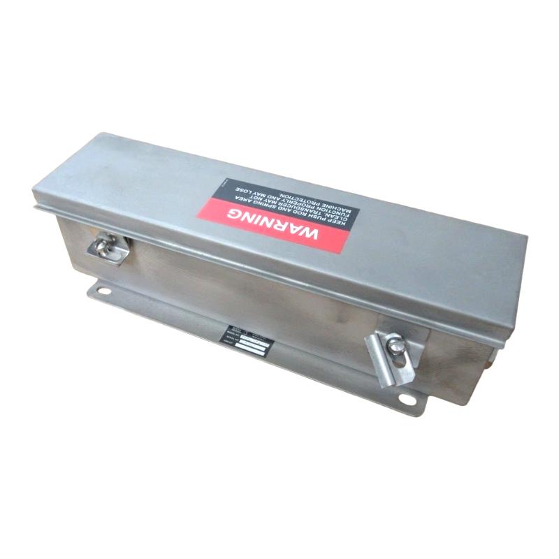
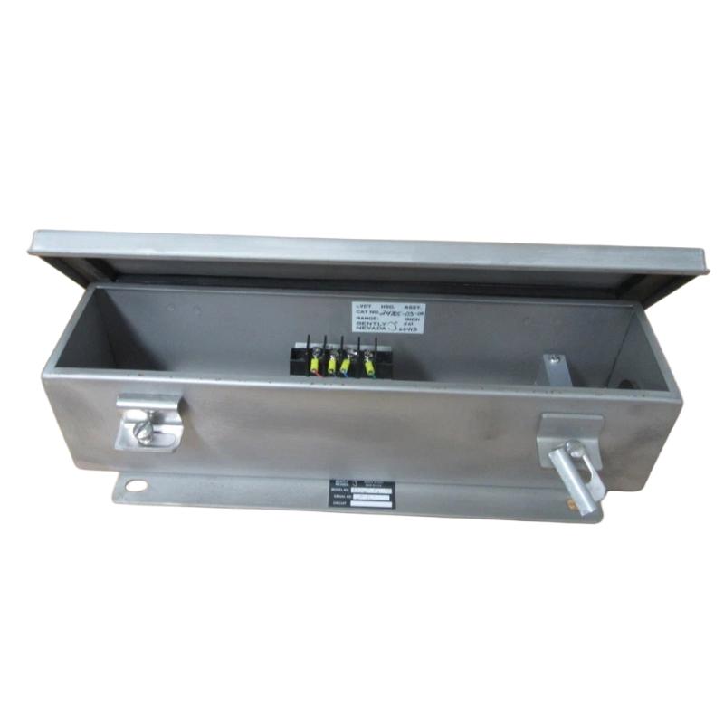
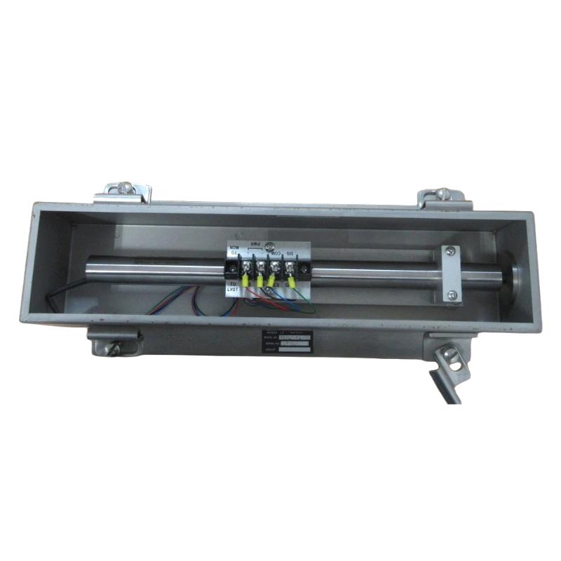
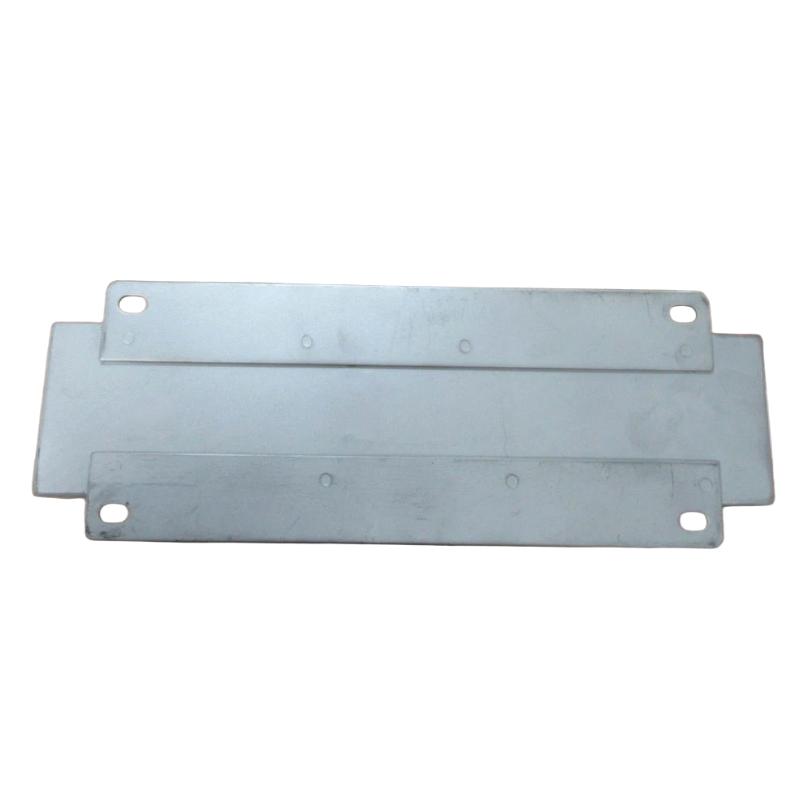
- Bently Nevada
- 24765-03-00
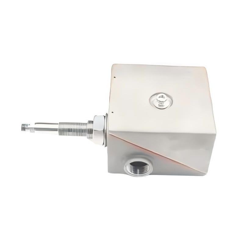
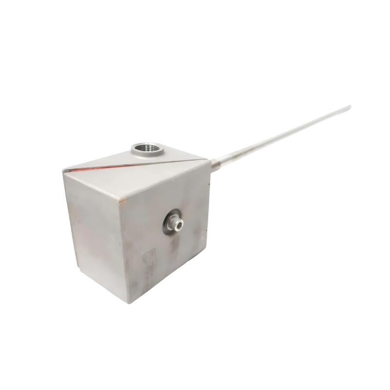
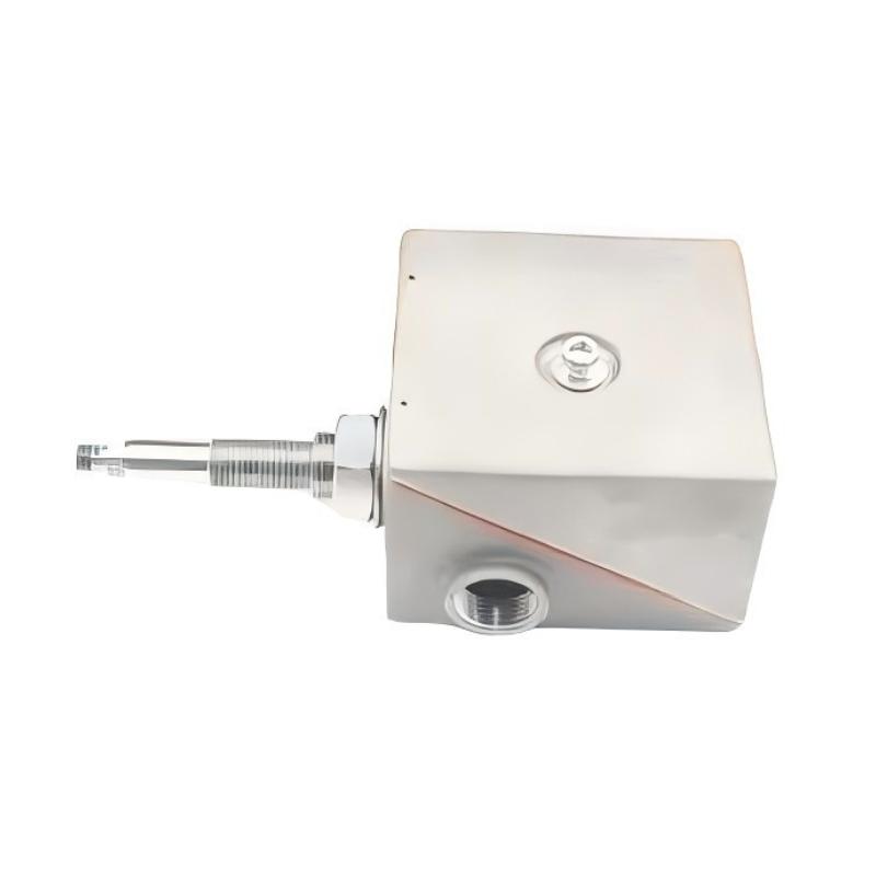
- Case Expansion Transducer Assembly
- USA
- 88.9 × 117 × 328 mm
- 2.7 kg
- Xiamen, China
- New & In Stock
- T/T, PayPal, Western Union
- 1 Year
- 1-3 Working Days
- DHL, UPS, TNT, FedEx and EMS.
- 24-Hour Service
- COO
- 3
Our advantage

Global Logistics
We have a 10-year logistics and express cooperation agreement, so our products can be shipped to any place in the world.

Brand new and original
Our products are imported in bulk from the place of origin. Because of the cooperative relationship, our products are all original and 100% new.

24-hour service
We provide 7*24 hours service to our customers. We will be there whenever you need us.

Price advantage
All our products are priced very favorably because we have our own warehouse and supply.
| Company Information | |||
| [email protected] | |||
| Mobile | +8615980777398 | ||
| +8615980777398 | |||
| 15980777398 |
Product Overview
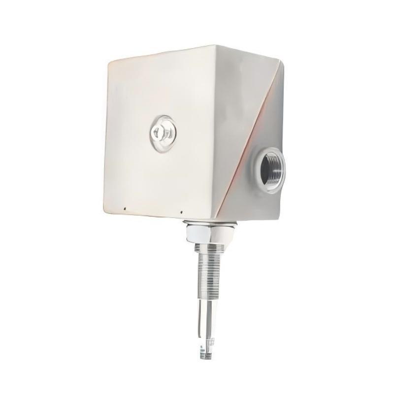
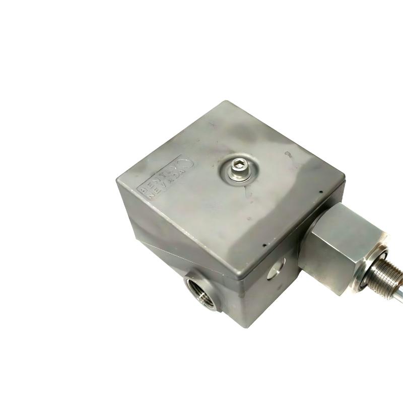
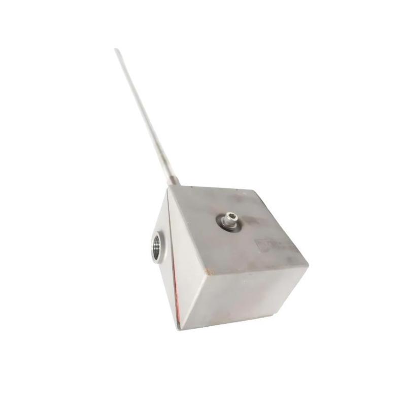
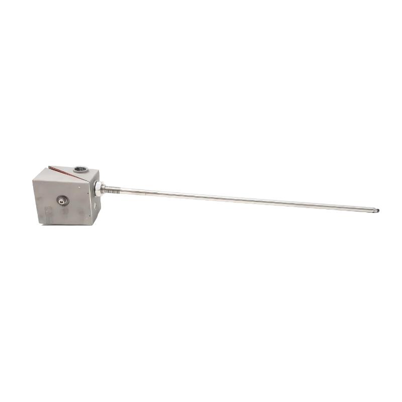
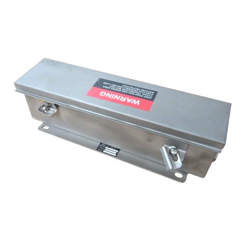
The Bently Nevada 24765-03-00 Case Expansion Transducer Assembly is a displacement measurement device used to monitor the thermal growth of large rotating machinery. It belongs to the 24765 DC LVDT case expansion transducer series and measures movement of a machine casing relative to its foundation or another fixed reference point.
This measurement is particularly important on large steam turbines and other machinery whose casing expands as operating temperatures rise. During startup, the stationary casing and rotating components may heat up at different rates. If their relative thermal growth is not properly monitored, clearances can change and create a risk of rubbing between rotating and stationary parts.
The 24765-03-00 uses a linear variable differential transformer (LVDT) to detect mechanical displacement and convert it into an electrical signal. Its 101.6 mm linear measurement range makes it suitable for applications requiring a comparatively large displacement range. The output sensitivity is 0.143 V/mm, allowing a compatible monitoring system to interpret changes in casing position.
In a turbine installation, the transducer is typically mounted near the machine foundation at a location where casing movement can be measured relative to the reference structure. As the turbine warms up, the casing moves along its expansion direction, and the transducer follows that movement through its mechanical sensing arrangement. The resulting signal helps operators assess whether thermal expansion is progressing as expected.
Case expansion is not the same measurement as shaft vibration or shaft axial position. Shaft measurements describe the behavior of rotating components, while case expansion monitoring focuses on movement of the stationary machine casing. Evaluating these measurements together gives plant personnel a more complete picture of machine behavior during startup and changing operating conditions.
The 24765-03-00 is especially relevant to turbine supervisory instrumentation systems where casing movement is an established monitoring parameter. Its electrical output must be matched to the receiving monitor, and its mechanical mounting must allow the sensing core to follow the intended direction of movement without binding.
For maintenance teams, the main value of this assembly lies in observing gradual displacement over the operating cycle. A change in the measured expansion trend can indicate unusual thermal behavior, restricted casing movement, or a mechanical condition that warrants further investigation. The transducer supplies measurement data; the monitoring system and operating procedures determine how that information is interpreted and acted upon.
Technical Specifications
| Parameter | Specification |
|---|---|
| Manufacturer | Bently Nevada |
| Model | 24765-03-00 |
| Product Type | Case Expansion Transducer Assembly |
| Transducer Technology | DC Linear Variable Differential Transformer (LVDT) |
| Product Series | 24765 Case Expansion Transducer |
| Measurement Parameter | Machine casing thermal expansion |
| Linear Measurement Range | 101.6 mm (4.00 in) |
| Scale Factor | 0.143 V/mm (3.63 V/in) |
| Frequency Response (-3 dB) | 10 Hz |
| Linearity | ±0.5% of full range |
| Stability | 0.125% of full scale |
| Nominal Output Impedance | 7 kΩ |
| Minimum Load Resistance | 200 kΩ |
| Input Power | +24 V DC |
| Minimum Supply Current | 30 mA |
| Mechanical Core-End Thread | 6-40 UNF-2B |
| Machine-End Thread | 1/4-20 UNC-2A |
| Spring Return | Not included in the 0-0 configuration |
| Operating Temperature | -18°C to +71°C |
| Storage Temperature | -54°C to +93°C |
| Dimensions | 88.9 × 117 × 328 mm |
| Weight | 2.7 kg |
Product Features
- Large displacement range: Measures casing movement over a 101.6 mm linear range.
- DC LVDT technology: Converts mechanical displacement into a proportional electrical signal.
- Defined output sensitivity: Uses a scale factor of 0.143 V/mm for displacement interpretation.
- Low-frequency measurement response: The specified -3 dB frequency of 10 Hz suits gradual thermal-growth monitoring.
- Specified linearity: Maintains linearity within ±0.5% of full range under specified conditions.
- Measurement stability: Provides a stated stability of 0.125% of full scale.
- Turbine supervisory application: Supports monitoring of casing movement during startup and operation.
- Mechanical displacement tracking: Follows movement along the intended measurement axis.
- DC-powered operation: Uses a +24 V DC supply arrangement.
- Monitoring-system integration: Supplies a displacement signal for a compatible machinery monitoring channel.
Working Principle
The 24765-03-00 operates by converting the mechanical movement of a machine casing into an electrical signal. Its sensing element uses the LVDT principle: movement of a core within the transformer assembly changes the electrical relationship between its windings, producing an output associated with the core’s position.
Machine Casing Movement → Mechanical Core Displacement → LVDT Signal → Monitoring System → Expansion Trend
When a turbine heats up, its casing expands relative to the foundation. The transducer’s mechanical sensing arrangement follows this movement, and the resulting signal changes in proportion to the measured displacement within the specified linear range.
For the 24765-03-00, the scale factor is 0.143 V/mm. A compatible monitoring channel uses this sensitivity to interpret the output as casing displacement. Correct scaling is essential: if the receiving channel is configured for a different transducer sensitivity, the displayed displacement will not accurately represent the physical movement.
The 101.6 mm linear range suits installations where the expected casing travel is greater than that accommodated by the shorter-range versions of the 24765 series. The actual usable travel must still be considered alongside the mechanical installation, core position, and available movement at the mounting point.
The specified frequency response of 10 Hz reflects the assembly’s response characteristics rather than a requirement for the casing to move continuously at that frequency. Thermal expansion generally develops gradually, so the measurement is primarily used to follow changes in casing position during startup, heating, and operating transitions.
The output is connected to a compatible monitoring channel that can display the measured expansion and evaluate it against configured operating limits. The transducer itself does not determine whether the machine is safe to operate; alarm interpretation and protective actions depend on the monitoring system configuration and the plant’s operating procedures.
Mechanical installation has a direct effect on measurement quality. The sensing core must move freely along the intended axis, and the mounting arrangement must maintain the correct relationship between the machine casing and the reference structure. Binding, misalignment, or movement of the reference point can introduce errors that cannot be corrected simply by changing the electrical scaling.
Role in a Turbine Supervisory Instrumentation System
The Bently Nevada 24765-03-00 provides the casing displacement measurement used by a turbine supervisory instrumentation system to track thermal growth. Its output complements other machine measurements, including shaft vibration, shaft position, and differential expansion where those parameters are installed.
Machine Casing → 24765-03-00 Transducer → Compatible Monitoring Channel → Operator Display and Alarm Logic
| System Component | Function |
|---|---|
| Bently Nevada 24765-03-00 | Measures relative casing displacement associated with thermal expansion |
| Mechanical Mounting Assembly | Maintains the transducer’s measurement reference and alignment |
| DC Power Supply | Provides the required operating power |
| Transducer Signal Wiring | Carries the displacement-related electrical output |
| Compatible Machinery Monitor | Interprets the transducer signal using the appropriate scale factor |
| Turbine Supervisory Instrumentation | Combines casing expansion data with other machine measurements |
| Operator Interface | Displays the measured expansion trend and configured alarm status |
| Plant Control or Protection System | Uses monitoring information according to the installed control and protection design |
A dual-transducer arrangement can provide additional information about casing movement at different points. When configured with a compatible monitoring system, comparing the two measurements can help identify unequal movement or a condition in which a casing support or sliding foot is restricted.
Industrial Applications
| Application | Typical Use |
|---|---|
| Steam Turbine Monitoring | Tracking casing expansion during startup and changing load conditions |
| Large Turbine Installations | Measuring relative movement between the casing and foundation |
| Turbine Supervisory Instrumentation | Supplying casing expansion data to compatible monitoring channels |
| Power Generation Facilities | Monitoring thermal growth as part of machinery condition assessment |
| Industrial Turbomachinery | Observing casing movement during warm-up and operating transitions |
| Thermal Growth Analysis | Comparing measured casing displacement with expected operating trends |
| Casing Support Assessment | Helping identify abnormal movement associated with restricted support motion |
| Machinery Commissioning | Establishing baseline expansion behavior during controlled startup |
| Preventive Maintenance | Supporting trend-based investigation of changes in casing movement |
| Rotating Machinery Diagnostics | Providing complementary information alongside shaft and vibration measurements |
The assembly is intended for applications where casing displacement must be measured over a comparatively large linear range. The receiving monitor and mechanical installation must be suitable for the transducer’s electrical and displacement characteristics.
Installation and Maintenance
- Confirm the measurement objective: Establish the intended casing movement direction and reference point before selecting the mounting location.
- Check the mounting arrangement: Ensure the transducer can follow the required casing movement without interference from adjacent structures or components.
- Align the sensing axis: Position the assembly so that its mechanical core follows the intended direction of displacement rather than an unintended lateral movement.
- Verify core travel: Confirm that the expected casing movement remains within the usable linear range and that sufficient travel is available in both directions.
- Inspect the mechanical linkage: Check the connection between the sensing core and the moving reference point for looseness, binding, or excessive mechanical play.
- Confirm the power supply: Provide the specified +24 V DC input and verify the supply arrangement before energizing the transducer.
- Match the receiving channel: Configure the monitoring system for the 0.143 V/mm scale factor and the correct measurement range.
- Check signal wiring: Inspect wiring terminations, insulation, grounding practices, and cable routing for conditions that could affect signal integrity.
- Establish a baseline: Record the transducer output and corresponding casing position under a known mechanical condition during commissioning.
- Observe startup trends: Compare the measured expansion profile with the machine’s expected thermal-growth behavior throughout warm-up.
- Investigate abnormal readings: If the signal changes unexpectedly, check the mounting, core movement, wiring, supply, and monitoring-channel configuration before concluding that the machine casing is moving abnormally.
- Maintain calibration records: Document the configured scale factor, baseline readings, inspection findings, and any changes to the mechanical installation or monitoring channel.
When readings become unstable or depart from the expected expansion trend, investigate the mechanical reference and sensing movement first. Electrical interference, incorrect channel scaling, and restrictions in the mounting arrangement can all affect the measurement and should be distinguished from genuine changes in casing behavior.
Related Components
| Component | Function |
|---|---|
| Bently Nevada 24765-03-00 | Measures casing displacement over the specified linear range |
| Compatible Machinery Monitor | Converts the transducer output into an engineering-unit measurement |
| DC Power Supply | Supplies operating power to the transducer |
| Transducer Signal Cable | Carries the output signal to the monitoring channel |
| Mechanical Mounting Bracket | Positions the transducer relative to the casing and reference structure |
| Casing Connection Hardware | Transfers casing movement to the sensing mechanism |
| Second Case Expansion Transducer | Provides a second measurement point in a dual-transducer arrangement |
| Operator Display | Presents expansion values and trends |
| Machinery Protection System | Uses configured monitoring information for alarms or protective actions |
Recommended Related Models
| Model | Product Type | Typical Application |
|---|---|---|
| Bently Nevada 24765-01 | DC LVDT Case Expansion Transducer Assembly | Casing displacement measurement with a ±12.7 mm linear range |
| Bently Nevada 24765-02 | DC LVDT Case Expansion Transducer Assembly | Casing displacement measurement with a ±25.4 mm linear range |
| Bently Nevada 24765-03 | DC LVDT Case Expansion Transducer Assembly | Casing displacement measurement with a ±51 mm linear range |
| Bently Nevada 135613-01 | High-Temperature Case Expansion Transducer System | Case expansion measurement in applications requiring the high-temperature transducer configuration |
| Bently Nevada 135613-02 | High-Temperature Case Expansion Transducer System | High-temperature casing displacement measurement over a 50.8 mm range |
| Bently Nevada 135613-03 | High-Temperature Case Expansion Transducer System | High-temperature casing displacement measurement over a 101.6 mm range |
Key Advantages
- Measures thermal casing movement relative to a fixed reference.
- Provides a 101.6 mm linear measurement range.
- Uses a defined scale factor of 0.143 V/mm.
- Supports casing expansion monitoring during turbine startup and operation.
- Offers specified linearity of ±0.5% of full range.
- Supplies displacement information for compatible machinery monitoring systems.
- Complements shaft vibration and other turbine supervisory measurements.
Technical FAQs
Why is the 24765-03-00 suitable for measuring turbine casing expansion?
Its LVDT sensing arrangement measures linear displacement, and its 101.6 mm range accommodates comparatively large casing movement. The 0.143 V/mm scale factor allows a compatible monitor to convert the output into a displacement measurement.
How should the monitoring channel be configured for this transducer?
The receiving channel must be compatible with the transducer’s electrical output and configured for the specified 0.143 V/mm sensitivity. The measurement range and reference direction must also correspond to the actual mechanical installation. Incorrect scaling can cause the displayed expansion to differ from the physical displacement.
What is the difference between casing expansion and differential expansion monitoring?
Casing expansion measures movement of the machine casing relative to a reference structure. Differential expansion concerns the relative thermal movement between the rotor and casing. These measurements describe different mechanical relationships and should not be treated as interchangeable.
What could cause the measured casing expansion to remain unchanged during turbine warm-up?
Possible causes include a restricted sensing core, a loose mechanical connection, a failed or incorrectly powered transducer, damaged signal wiring, or an incorrectly configured monitoring channel. Confirming the mechanical movement and checking the electrical signal can help distinguish an instrumentation fault from an actual lack of casing movement.