

ProductPRODUCT
Featured products
Contact Us
- Allen Bradley
- 20LD650ACENNAE11WA
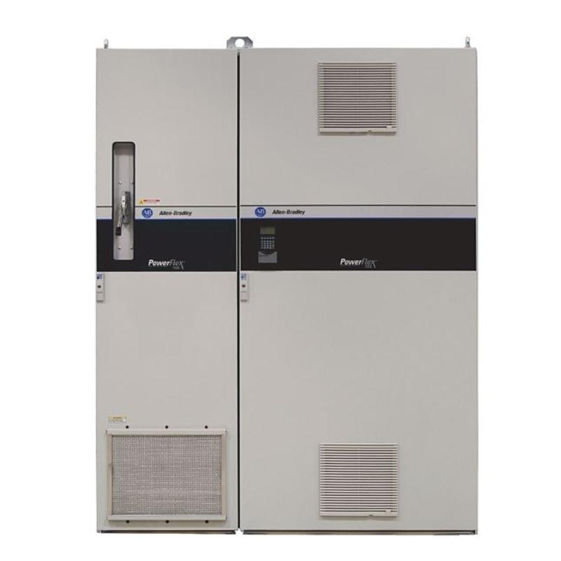
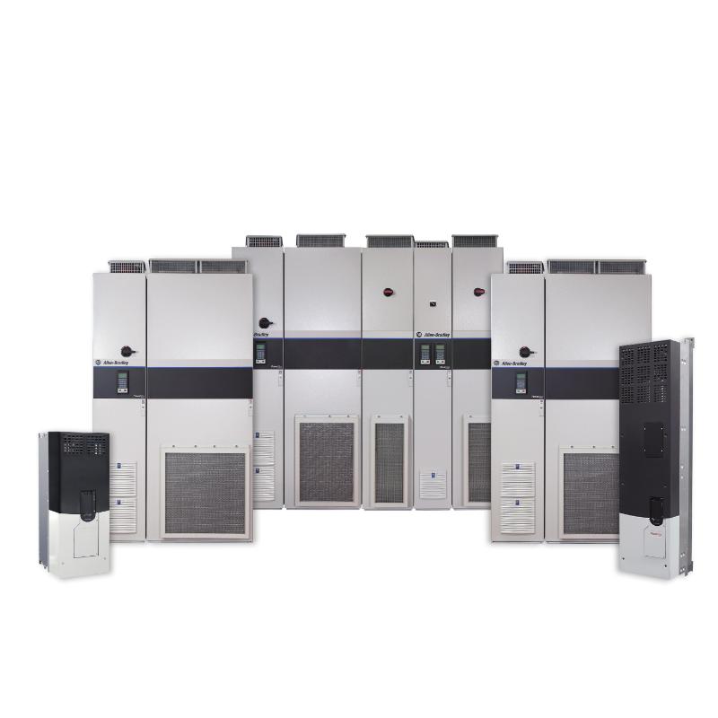
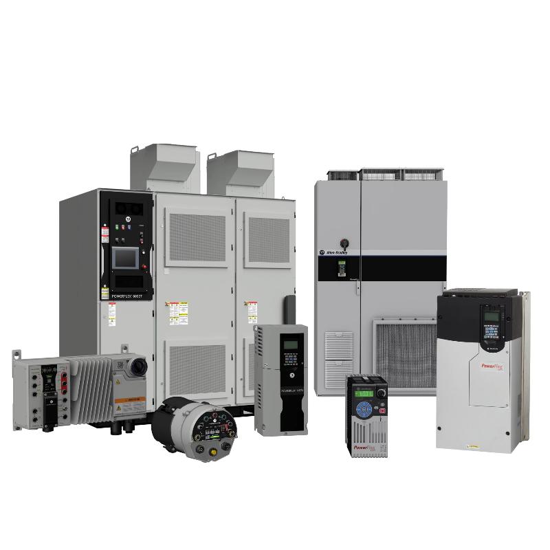
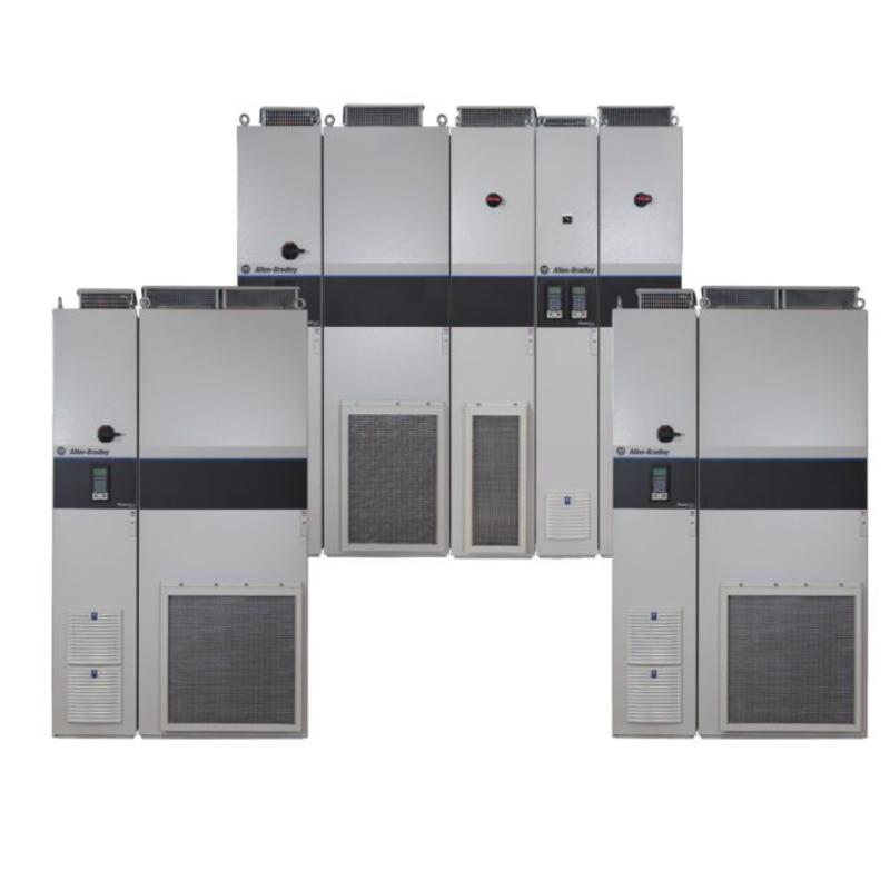
- PowerFlex 700L AC Drive
- USA
- 2078 × 1200 × 536 mm
- 951 kg
- Xiamen, China
- New & In Stock
- T/T, PayPal, Western Union
- 1 Year
- 1-3 Working Days
- DHL, UPS, TNT, FedEx and EMS.
- 24-Hour Service
- COO
- 12
Our advantage

Global Logistics
We have a 10-year logistics and express cooperation agreement, so our products can be shipped to any place in the world.

Brand new and original
Our products are imported in bulk from the place of origin. Because of the cooperative relationship, our products are all original and 100% new.

24-hour service
We provide 7*24 hours service to our customers. We will be there whenever you need us.

Price advantage
All our products are priced very favorably because we have our own warehouse and supply.
| Company Information | |||
| [email protected] | |||
| Mobile | +8615980777398 | ||
| +8615980777398 | |||
| 15980777398 |
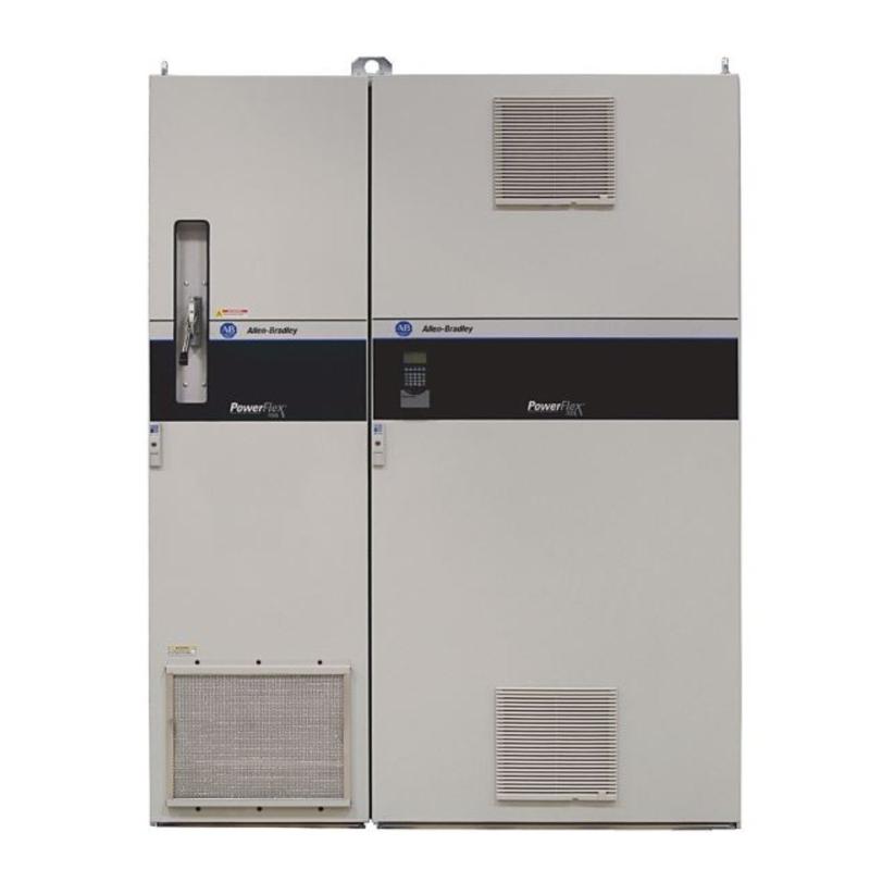
Product Overview
The Allen Bradley 20LD650ACENNAE11WA PowerFlex 700L AC Drive is a high-power industrial drive intended for applications where large AC motors require controlled speed, torque, and acceleration. As part of the PowerFlex 700L liquid-cooled drive family, it combines motor-control electronics with a liquid-cooling arrangement suited to demanding industrial installations.
At this power level, drive selection affects more than motor speed. A production line may need to accelerate a heavily loaded conveyor without creating excessive mechanical stress, while a process machine may require accurate speed regulation as material resistance changes. In these situations, the drive adjusts the electrical output supplied to the motor to meet the operating demand and maintain the required motion profile.
The 20LD650 designation identifies the 650 A, 400/480 V-class drive platform, with the 20LD650 family rated for applications up to 600 hp (445 kW) in normal-duty operation at 480 V. Its published heavy-duty rating is 440 hp (325 kW). Actual application capacity depends on the motor, load profile, ambient conditions, cooling system, and applicable duty rating.
Liquid cooling is a defining characteristic of the PowerFlex 700L platform. Power semiconductors generate substantial heat as they switch and regulate motor power. The cooling circuit transfers heat away from the drive’s power section, supporting operation at high power levels without relying solely on heat dissipation into the surrounding cabinet air. Coolant quality, flow, temperature, and maintenance therefore form part of the overall drive installation.
The PowerFlex 700L family supports vector-based motor control as well as configurable V/Hz operation. The appropriate method depends on the motor, the application’s torque requirements, and the level of speed regulation needed. A high-inertia load, for example, may require a carefully configured acceleration and deceleration profile, whereas a process pump or conveyor may place greater emphasis on maintaining a defined operating speed.
For maintenance teams, the important areas are power connections, control wiring, cooling performance, drive diagnostics, and motor behavior under load. An overheating alarm, unexpected current limit, or unstable speed response can result from several causes, including cooling restrictions, incorrect motor parameters, excessive load demand, or a fault in the connected equipment. Evaluating the drive and its operating environment together helps identify the actual cause.
Technical Specifications
| Parameter | Specification |
|---|---|
| Manufacturer | Allen-Bradley |
| Model | 20LD650ACENNAE11WA |
| Product Type | PowerFlex 700L AC Drive |
| Product Family | PowerFlex 700L |
| Drive Category | Liquid-Cooled AC Drive |
| Drive Frame | Frame 3A |
| Voltage Class | 400/480 V |
| Rated Output Current | 650 A |
| Normal-Duty Power Rating at 480 V | 600 hp (445 kW) |
| Heavy-Duty Power Rating at 480 V | 440 hp (325 kW) |
| Input Phases | 3-phase |
| Output Phases | 3-phase |
| Output Frequency Range | 0–420 Hz |
| Motor Control Methods | Vector control and V/Hz control, subject to configuration |
| Cooling Method | Liquid cooling |
| Maximum Surrounding Air Temperature Without Derating | 40°C for Frame 3A |
| Maximum Rated-Current Altitude | 1,000 m |
| Dimensions | 2078 × 1200 × 536 mm |
| Weight | 951 kg |
Product Features
- High-current motor control: The 650 A drive platform supports large industrial AC motors.
- Liquid-cooled power section: Transfers heat from the power electronics into the cooling circuit.
- Vector-control capability: Supports applications requiring controlled motor speed and torque.
- Configurable V/Hz operation: Suits applications where a voltage-to-frequency control method is appropriate.
- Wide output-frequency range: Supports motor operation across a range of application-specific speeds.
- Programmable acceleration and stopping: Allows the drive response to be adapted to the load and machine sequence.
- Integrated control functions: Supports configurable motor-control behavior, current limiting, and drive fault handling.
- Industrial control interfaces: Provides control and communication options according to the installed configuration.
- Large-drive installation format: Suits industrial electrical rooms and equipment assemblies built for high-power motor control.
Working Principle
The 20LD650ACENNAE11WA regulates the power delivered to an AC motor by controlling the switching of its power electronics. Rather than supplying the motor directly from the fixed-frequency mains, the drive adjusts its output voltage and frequency according to the configured motor-control method and the commanded operating conditions.
AC Supply → Power Conversion Stage → Controlled AC Output → Motor → Industrial Load
When the controller requests a speed change, the drive adjusts the output supplied to the motor. The motor then accelerates or decelerates according to the commanded profile and the torque required by the connected load. Current feedback and internal control algorithms help the drive regulate operation and respond to changing conditions.
In a large conveyor system, for example, a sudden speed command can create high mechanical stress if the motor accelerates too quickly. The drive’s acceleration ramp allows the conveyor to build speed progressively. During deceleration, the selected stopping method determines how the drive reduces motor speed and handles the resulting energy. The appropriate settings depend on the load’s inertia and the machine’s stopping requirements.
Vector control can provide more direct control of motor torque and speed than basic V/Hz operation when the application and configuration support it. This can be useful in machinery where load torque varies or where speed regulation must be maintained over a broad operating range. The selected motor-control method should match the motor type and the required performance.
The liquid-cooling system handles heat produced by the power section. As the drive switches electrical power, losses occur in the semiconductor devices and associated components. Coolant carries heat away from the power electronics and transfers it through the cooling circuit. If coolant flow is restricted, the temperature is outside the permitted range, or the heat exchanger cannot dissipate the load, the drive may experience thermal alarms or protective shutdowns.
The drive also monitors operating conditions and responds to faults according to its configuration. Current limits, overvoltage protection, undervoltage detection, and other protective functions help prevent operation outside defined limits. These functions do not replace correct system sizing, suitable upstream protection, or the machine’s required safety provisions.
Role in a PowerFlex 700L Industrial Drive System
The 20LD650ACENNAE11WA acts as the main motor-control unit between the incoming electrical supply and a compatible high-power AC motor. It receives operating commands from the machine-control system, regulates motor output, and monitors electrical and thermal conditions during operation.
Industrial AC Supply → PowerFlex 700L Drive → AC Motor → Mechanical Transmission → Industrial Process
| System Component | Function |
|---|---|
| Allen-Bradley 20LD650ACENNAE11WA | Regulates power delivered to the connected AC motor |
| Upstream Electrical Protection | Protects the supply circuit according to the installation design |
| Machine Controller | Issues operating commands and coordinates machine sequences |
| Operator Interface | Allows operators to monitor status and enter permitted commands |
| AC Motor | Converts electrical power into mechanical rotation |
| Liquid-Cooling Circuit | Removes heat from the drive’s power section |
| Coolant Heat Exchanger | Transfers heat from the coolant to the cooling medium or surrounding system |
| Motor Feedback Device, Where Fitted | Supplies speed or position feedback when supported by the selected configuration |
| Mechanical Transmission | Transfers motor output to the driven equipment |
| Drive Communication Network | Exchanges commands and status with compatible control equipment |
The drive’s cooling circuit and electrical control system must both remain within their operating limits. Motor performance depends on the complete installation, including supply quality, load characteristics, motor configuration, and cooling capacity.
Industrial Applications
| Application | Typical Use |
|---|---|
| Large Conveyor Systems | Controlling belt speed and managing acceleration under changing material loads |
| Mining and Bulk Material Handling | Driving high-power conveying and processing equipment |
| Industrial Pumps | Regulating motor speed to match process flow requirements |
| Large Fans and Blowers | Adjusting airflow and controlling motor acceleration |
| Process Machinery | Maintaining defined motor speeds during continuous production |
| Paper and Converting Equipment | Coordinating drive speeds across material-processing stages |
| Metal Processing Lines | Controlling high-power rotating equipment and material-feed mechanisms |
| Heavy Manufacturing | Operating large motors within defined torque and speed limits |
| Industrial Test Systems | Controlling motor-driven loads during repeatable operating sequences |
| Centralized Drive Installations | Integrating high-power motor control into industrial electrical rooms |
The appropriate application depends on the motor’s power requirements, the required torque and speed behavior, and the available cooling infrastructure. A drive rated for a particular current must also be selected according to the intended normal-duty or heavy-duty operating conditions.
Installation and Maintenance
- Prepare the installation area: Provide a suitable industrial location with sufficient access for electrical work, cooling-system service, and inspection of the drive assembly.
- Check the electrical supply: Confirm that the incoming supply voltage, phase arrangement, fault level, and upstream protective devices suit the drive installation.
- Plan the cabinet and equipment layout: Allow the space needed for power connections, control wiring, coolant piping, and service access.
- Inspect power connections: Check terminals, bus connections, cable routing, and grounding arrangements before energizing the equipment.
- Prepare the liquid-cooling circuit: Use the specified coolant type and maintain the required flow, temperature, and pressure conditions for the installed drive configuration.
- Inspect coolant connections: Check fittings, hoses, and piping for leakage, damage, or contamination before commissioning.
- Connect control wiring: Separate control and power wiring appropriately and check the termination of command, status, and communication connections.
- Configure motor data: Enter the connected motor’s applicable nameplate data and select the appropriate control method and operating limits.
- Test the drive without unnecessary load: Follow the commissioning procedure to check drive readiness, fault status, control response, and cooling operation before full-load operation.
- Validate acceleration and stopping: Test the machine’s operating ramps and stopping behavior under controlled conditions, paying attention to load inertia and mechanical stress.
- Monitor thermal and electrical conditions: Review drive alarms, current demand, operating temperature, and coolant performance during operation.
- Record maintenance findings: Document drive settings, coolant inspection results, fault history, and corrective actions to support future troubleshooting.
When a drive trips under load, check the fault record before changing operating parameters. Cooling restrictions, excessive current demand, incorrect motor data, supply disturbances, and mechanical overloads can produce different symptoms and require different corrective actions.
Related Components
| Component | Function |
|---|---|
| Allen-Bradley 20LD650ACENNAE11WA | PowerFlex 700L liquid-cooled AC drive |
| Compatible High-Power AC Motor | Converts regulated electrical output into mechanical power |
| Upstream Circuit Breaker or Fuse Assembly | Provides supply-side electrical protection |
| Motor Power Cable | Connects the drive output to the motor |
| Control Wiring Assembly | Carries operating commands and status signals |
| Industrial Controller | Coordinates drive operation with the machine sequence |
| Operator Interface | Displays drive status and permits configured operator commands |
| Liquid-Cooling Piping | Circulates coolant through the cooling system |
| Coolant Heat Exchanger | Removes heat from the circulating coolant |
| Industrial Communication Interface | Supports control and monitoring through the installed communication option |
| Protective Grounding Assembly | Provides the required protective electrical connection |
Recommended Related Models
| Model / Product Reference | Product Type | Typical Application |
|---|---|---|
| Allen-Bradley 20LD360 | PowerFlex 700L AC Drive | Lower-current 480 V-class liquid-cooled drive applications |
| Allen-Bradley 20LD650 | PowerFlex 700L AC Drive | 650 A, 480 V-class drive applications |
| Allen-Bradley 20LD1K2 | PowerFlex 700L AC Drive | Higher-current 480 V-class applications |
| Allen-Bradley 20LC650 | PowerFlex 700L AC Drive | 650 A drive applications in the 400 V-class family |
| Allen-Bradley 20LE800 | PowerFlex 700L AC Drive | Higher-power applications in the 600/690 V-class family |
| Allen-Bradley PowerFlex 700S | AC Drive | Industrial applications requiring configurable vector-based motor control |
Key Advantages
- Supports high-power AC motor control at the 650 A drive rating.
- Uses liquid cooling to manage heat from the power electronics.
- Offers vector-control and V/Hz operating methods according to configuration.
- Allows programmable acceleration, deceleration, and stopping behavior.
- Supports integration into industrial control and monitoring systems.
- Provides drive diagnostics to assist fault investigation and maintenance.
Technical FAQs
What is the difference between the normal-duty and heavy-duty ratings of the 20LD650 drive family?
The published 480 V ratings distinguish between 600 hp (445 kW) normal-duty operation and 440 hp (325 kW) heavy-duty operation. The correct rating depends on the motor’s load profile and the required overload capability. Applications with frequent acceleration or sustained high torque may need to be assessed against the heavy-duty rating.
Why does the PowerFlex 700L use liquid cooling?
At high power levels, the drive’s semiconductor devices generate substantial heat. Liquid cooling transfers heat away from the power section through a coolant circuit, reducing the amount that must be dissipated directly into the surrounding cabinet air. The cooling system must maintain the specified coolant conditions for the drive to operate within its thermal limits.
Which motor-control method is appropriate for this drive?
Vector control may be suitable when an application requires closer control of motor torque and speed, while V/Hz control can suit applications with less demanding regulation requirements. Selection depends on the connected motor, operating range, load behavior, and the drive’s configured capabilities.
What should be checked if the drive trips during high-load operation?
Start with the recorded fault code and the conditions present at the time of the trip. Review motor current, acceleration settings, load demand, incoming supply conditions, and the coolant circuit. Repeated trips should be investigated by addressing the underlying cause rather than simply increasing current limits or disabling protective functions.