

ProductPRODUCT
Featured products
Contact Us
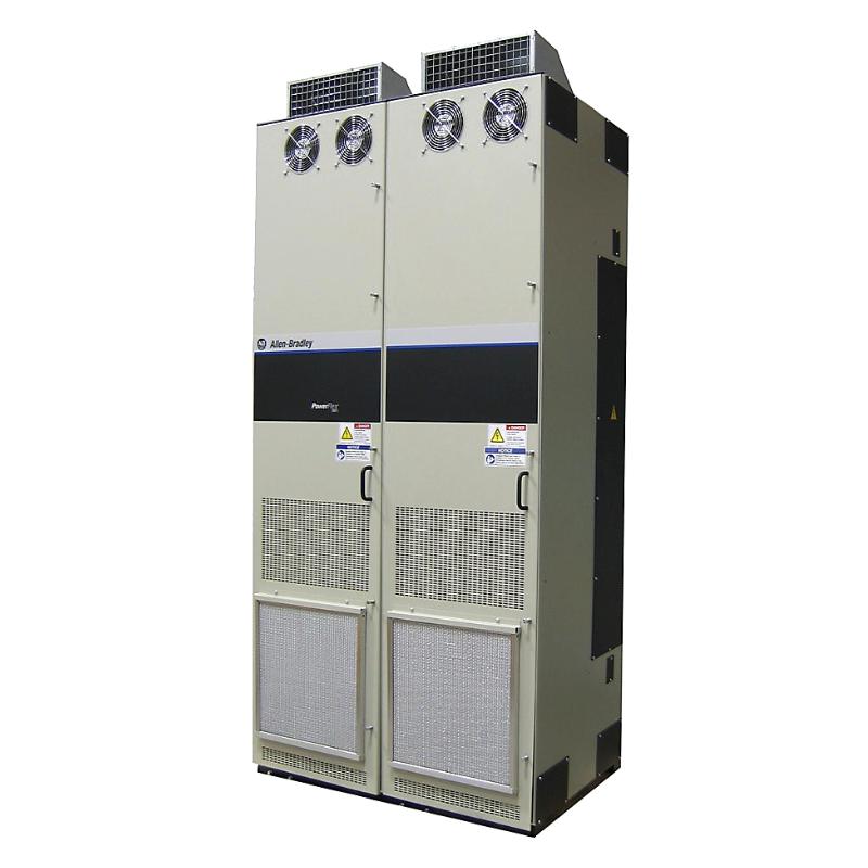
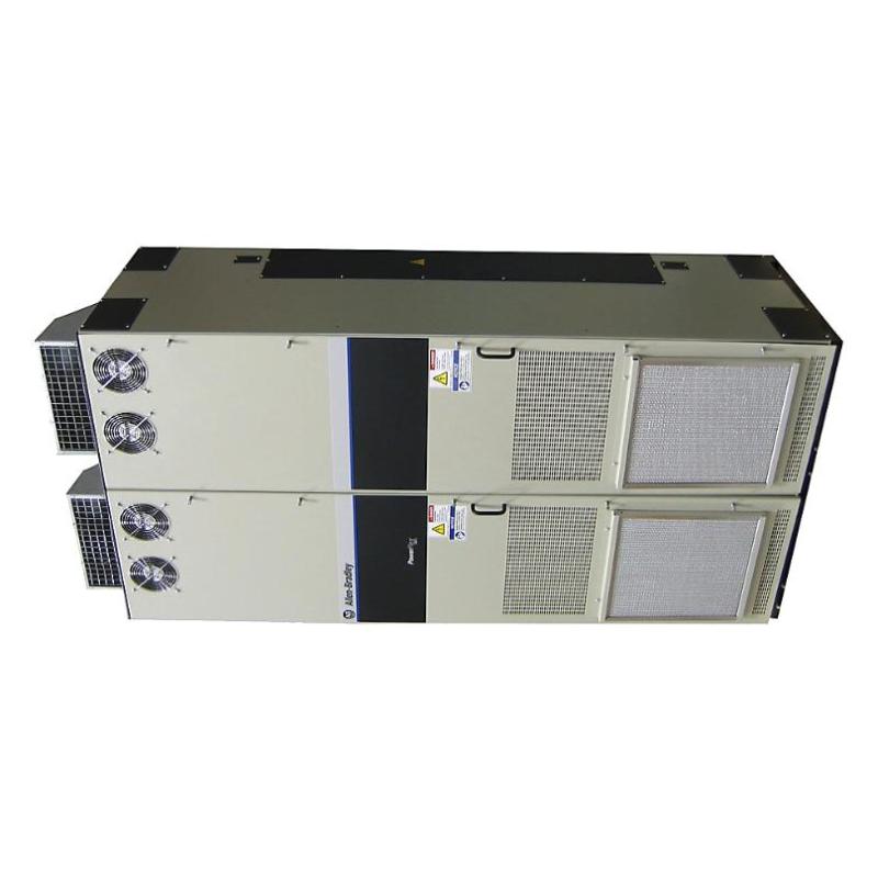
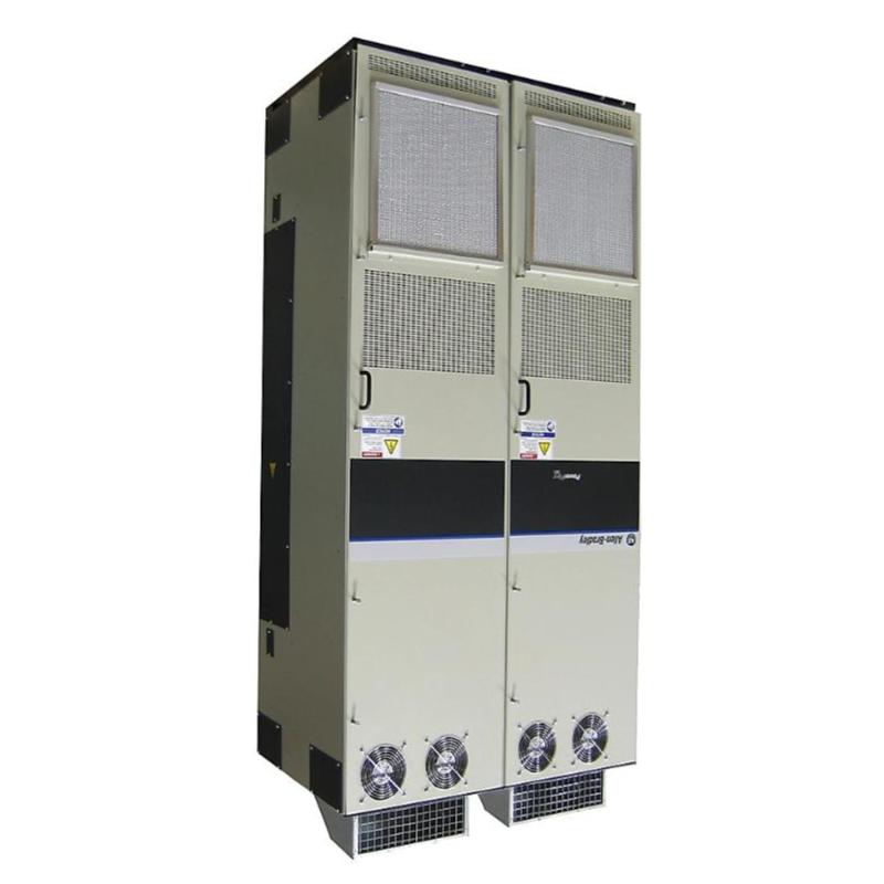
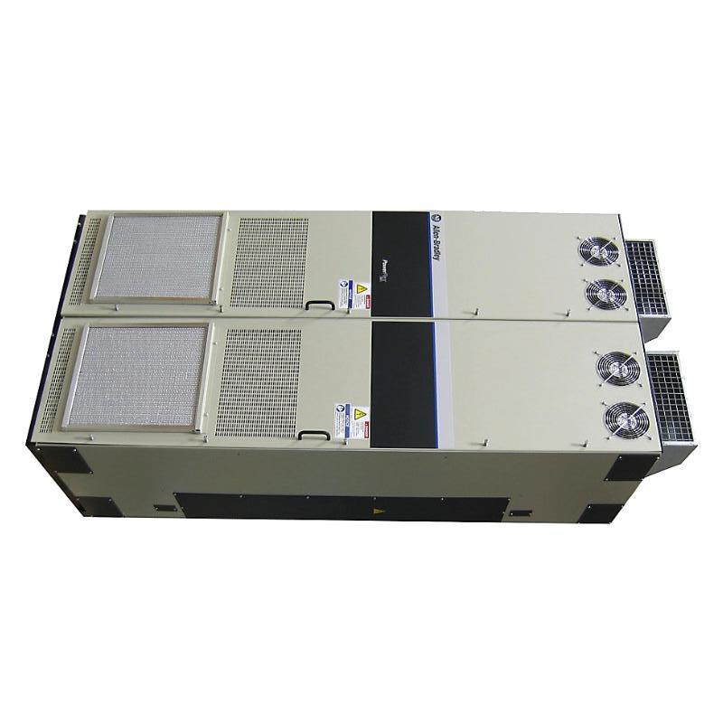
- Allen Bradley
- 20G11BC910JN0NNNNN
- PowerFlex 755 AC Drive
- USA
- 2453 × 600 × 1200 mm
- 1246 kg
- Xiamen, China
- New & In Stock
- T/T, PayPal, Western Union
- 1 Year
- 1-3 Working Days
- DHL, UPS, TNT, FedEx and EMS.
- 24-Hour Service
- COO
- 59
Our advantage

Global Logistics
We have a 10-year logistics and express cooperation agreement, so our products can be shipped to any place in the world.

Brand new and original
Our products are imported in bulk from the place of origin. Because of the cooperative relationship, our products are all original and 100% new.

24-hour service
We provide 7*24 hours service to our customers. We will be there whenever you need us.

Price advantage
All our products are priced very favorably because we have our own warehouse and supply.
| Company Information | |||
| [email protected] | |||
| Mobile | +8615980777398 | ||
| +8615980777398 | |||
| 15980777398 |
Product Overview
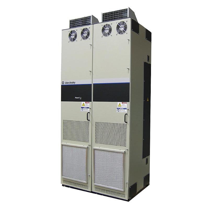
The Allen Bradley 20G11BC910JN0NNNNN is a PowerFlex 755 AC Drive for industrial motor control applications requiring variable-speed operation and integration with a larger automation system. As part of the PowerFlex 755 platform, it is suited to demanding machine and process environments where motor performance needs to be coordinated with production requirements.
A PowerFlex 755 installation typically places the drive between the plant electrical supply and the motor, with the drive managing the motor’s operating behavior according to configured parameters and external commands. This arrangement is useful when a process requires more than simple motor starting and stopping, such as controlled acceleration, speed regulation, coordinated operation, or process-dependent motor control.
The drive can be applied to large industrial equipment where motor operation directly affects production throughput or process stability. Typical examples include material-handling systems, pumps, fans, compressors, conveyors, and other continuously operating machinery.
Technical Specifications
| Parameter | Specification |
|---|---|
| Manufacturer | Allen Bradley |
| Part Number | 20G11BC910JN0NNNNN |
| Product Family | PowerFlex 750-Series |
| Product Type | PowerFlex 755 AC Drive |
| Application | Industrial AC Motor Control |
| Dimensions | 2453 × 600 × 1200 mm |
| Weight | 1246 kg |
Product Features
- PowerFlex 755 platform — Provides an industrial AC drive platform for demanding variable-speed motor applications.
- Variable-frequency motor control — Regulates motor operation according to the configured application requirements.
- Industrial automation integration — Can be incorporated into PLC-based control architectures and larger plant automation systems.
- Process-oriented motor operation — Suitable for applications where motor speed and operating behavior need to follow changing process conditions.
- Large industrial equipment applications — Appropriate for substantial motor-driven machinery used in production and process facilities.
- Drive diagnostics — Operating and fault information can assist commissioning personnel and maintenance technicians during troubleshooting.
- Flexible control architecture — Can be used with different command, reference, and communication arrangements depending on the application.
Working Principle
The 20G11BC910JN0NNNNN regulates the electrical output supplied to an AC motor so that the motor can operate at the required speed and operating condition. The drive receives the configured command and reference information, processes the applicable control parameters, and adjusts its output accordingly.
A simplified operating path is:
Plant Power → PowerFlex 755 AC Drive → Controlled AC Output → Motor → Mechanical Load
Consider a large conveyor system. The production controller may request a specific operating speed based on material flow. Rather than running the motor continuously at one fixed speed, the PowerFlex 755 adjusts motor operation to follow the required reference.
In a pump or fan installation, the same principle can be used to match motor speed to process demand. This can make the drive part of the process-control strategy rather than simply an electrical switching device.
For commissioning, the relationship between the motor data, command source, speed reference, acceleration/deceleration settings, and external control system should be reviewed as a complete control loop.
Role in a PowerFlex 755 Motor Control System
| System Element | Function |
|---|---|
| PLC / Process Controller | Determines machine or process operating commands |
| PowerFlex 755 AC Drive | Controls motor speed and electrical output |
| AC Motor | Converts electrical power into mechanical motion |
| HMI / Operator Station | Provides monitoring, adjustment, and diagnostic access |
| Process Sensors | Supply operating information used by the control strategy |
| Industrial Network | Carries control, status, and diagnostic data where network communication is used |
| Mechanical Load | Represents the conveyor, pump, fan, compressor, or other driven equipment |
Industrial Applications
| Application | Typical Use |
|---|---|
| Large Conveyor Systems | Coordinating motor speed with material flow and production sequences |
| Pumping Systems | Adjusting motor operation to changing process demand |
| Fans and Blowers | Controlling airflow in industrial ventilation and process equipment |
| Compressors | Managing motor operation according to equipment loading |
| Material Processing | Matching motor speed to production requirements |
| Heavy Process Machinery | Providing variable-speed operation for large motor-driven equipment |
Installation and Maintenance
- Plan the installation area — Confirm that the electrical room, drive enclosure, foundation, and handling equipment are suitable for the intended installation.
- Verify the electrical system — Check the incoming supply, grounding arrangement, motor connections, protection equipment, and associated control wiring before energizing the drive.
- Confirm motor compatibility — Review the motor nameplate information and applicable drive parameters before commissioning.
- Configure the control architecture — Verify the selected command source, speed reference, communication settings, and process-control interface.
- Check ventilation and environmental conditions — Keep cooling paths clear and maintain the environmental conditions required for proper drive operation.
- Review fault and status information — Use available diagnostic information during commissioning and troubleshooting instead of immediately replacing hardware.
- Inspect the installation periodically — Check electrical connections, cooling arrangements, cabinet condition, and signs of abnormal operation during scheduled maintenance.
- Follow plant safety procedures — Properly isolate and discharge the drive according to the applicable site procedures before performing maintenance.
Related Components
| Component | Function / Relationship |
|---|---|
| Allen Bradley PowerFlex 755 AC Drive | Main variable-speed motor-control device |
| Allen Bradley ControlLogix PLC | Provides coordinated machine and process commands |
| Allen Bradley HMI | Provides operator monitoring and drive interface |
| AC Motor | Converts the drive output into mechanical motion |
| Industrial Network Hardware | Connects the drive with PLCs and other automation equipment |
| Motor Protection Equipment | Supports protection of the motor and electrical installation |
Recommended Related Models
| Model | Product Type | Typical Application |
|---|---|---|
| Allen Bradley 20G11BC910JN0NNNNN | PowerFlex 755 AC Drive | Large industrial AC motor control |
| Allen Bradley 20F1ANE144JN0NNNNN | PowerFlex 753 AC Drive | Industrial variable-speed motor control |
| Allen Bradley 20F1AND302AN0NNNNN | PowerFlex 753 AC Drive | Industrial AC motor applications |
| Allen Bradley 20F1AND361AA0NNNNN | PowerFlex 753 AC Drive | Variable-speed industrial equipment |
| Allen Bradley PowerFlex 755 Series | AC Drive | Advanced industrial motor control |
| Allen Bradley ControlLogix Controllers | Programmable Controller | PLC-based drive and process control |
Key Advantages
- Suitable for demanding industrial AC motor-control applications.
- Uses the PowerFlex 755 platform for larger and more advanced drive applications.
- Can be integrated with PLC-based machine and process-control systems.
- Supports variable-speed operation for changing production and process requirements.
- Applicable to conveyors, pumps, fans, compressors, and heavy process machinery.
- Provides drive operating and diagnostic information useful for commissioning and maintenance.
Technical FAQs
What makes the PowerFlex 755 suitable for demanding industrial motor-control applications?
The PowerFlex 755 platform is intended for industrial applications where motor operation needs to be coordinated with machinery and process requirements. It can be incorporated into automation architectures that require controlled speed, process coordination, monitoring, and drive diagnostics.
How does the 20G11BC910JN0NNNNN fit into a PLC-based control system?
The drive can serve as the motor-control layer between the automation controller and the physical motor. The PLC or process controller determines the required operating command or reference, while the PowerFlex 755 handles the corresponding motor-control task and returns available operating information to the control architecture.
Which drive parameters should be reviewed during PowerFlex 755 commissioning?
Motor nameplate data, command source, reference source, acceleration and deceleration behavior, and application-specific control parameters should be reviewed before placing the motor into normal service. The correct settings depend on the motor, mechanical load, and control strategy.
How can drive diagnostics help troubleshoot an industrial motor-control problem?
Drive status and fault information can help determine whether an issue is associated with the electrical supply, motor, configuration, control command, communication system, or mechanical load. Reviewing the fault condition together with the actual operating behavior is generally more useful than treating every trip as a drive hardware failure.