

ProductPRODUCT
Featured products
Contact Us
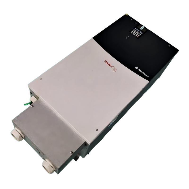
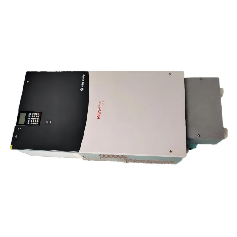
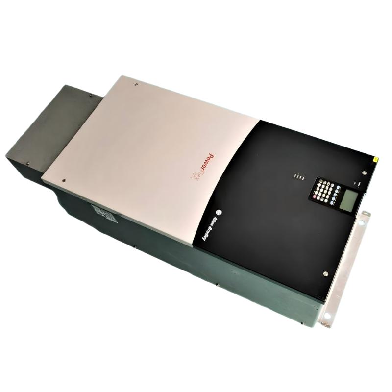
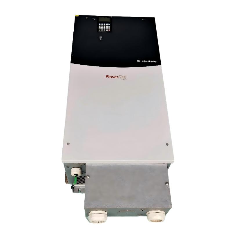
- Allen Bradley
- 20BW142A0ANNANC0
- PowerFlex 700 AC Drive
- USA
- 976.3 × 403.9 × 275.5 mm
- 71.44 kg
- Xiamen, China
- New & In Stock
- T/T, PayPal, Western Union
- 1 Year
- 1-3 Working Days
- DHL, UPS, TNT, FedEx and EMS.
- 24-Hour Service
- COO
- 6
Our advantage

Global Logistics
We have a 10-year logistics and express cooperation agreement, so our products can be shipped to any place in the world.

Brand new and original
Our products are imported in bulk from the place of origin. Because of the cooperative relationship, our products are all original and 100% new.

24-hour service
We provide 7*24 hours service to our customers. We will be there whenever you need us.

Price advantage
All our products are priced very favorably because we have our own warehouse and supply.
| Company Information | |||
| [email protected] | |||
| Mobile | +8615980777398 | ||
| +8615980777398 | |||
| 15980777398 |
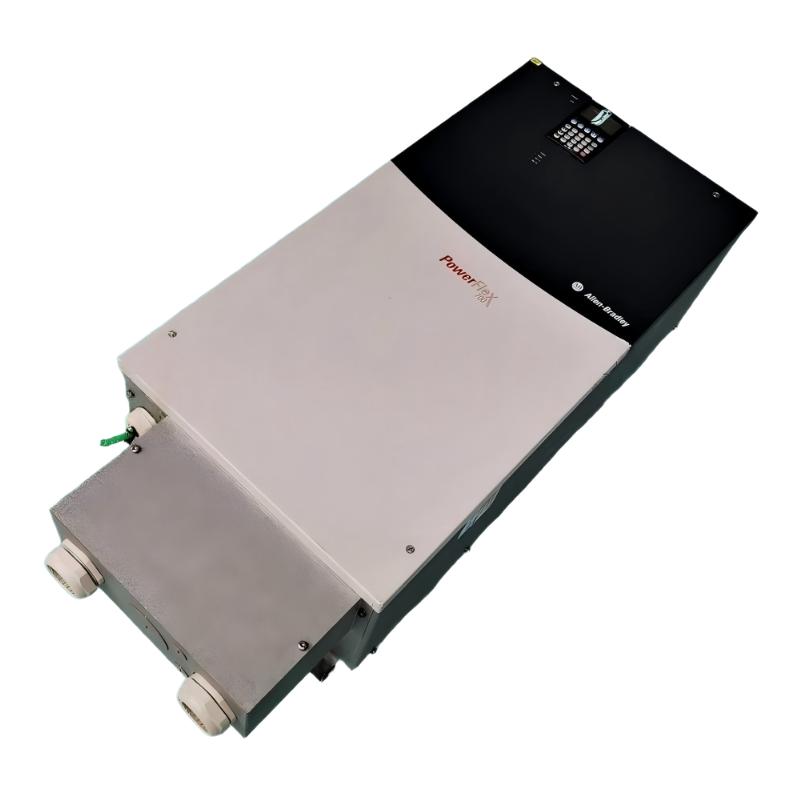
Product Overview
The Allen Bradley 20BW142A0ANNANC0 is a PowerFlex 700 adjustable-frequency AC drive with a rated output current of 142 A. This configuration uses a 932 V DC input with precharge and supports a normal-duty power rating of 132 HP and a heavy-duty rating of 110 HP. It uses vector control with 24 V DC I/O for integration into compatible industrial motor-control systems.
The PowerFlex 700 family is used in applications where motor speed and acceleration need to respond to changing operating requirements. By regulating the electrical output supplied to an AC motor, the drive allows equipment to operate at controlled speeds rather than relying exclusively on fixed-speed motor operation. This can be useful in material handling, processing machinery, and other installations where the motor’s operating profile affects the production sequence.
The 20BW142A0ANNANC0 has a specific DC-input configuration. Its 932 V DC supply arrangement includes precharge, which manages the initial charging of the drive’s DC-link circuit. This distinguishes it from PowerFlex 700 variants intended for conventional AC input and means that the associated power system must match the requirements of this model.
The catalog configuration includes an EMC filter with a common-mode choke and conformal coating. It is supplied without a Human Interface Module, internal brake IGBT, drive-mounted brake resistor, internal communication module, or feedback option. These details affect panel integration, commissioning, and the selection of any additional equipment required by the application.
The drive’s 24 V DC control I/O supports connection to compatible external control circuits. A PLC can coordinate start and stop commands, process references, interlocks, and available status signals, while the drive regulates motor operation according to its configured parameters.
For example, a large industrial conveyor may require controlled acceleration to reduce abrupt loading on belts, couplings, and gearboxes. The drive can manage the motor’s operating speed while a supervisory controller coordinates the conveyor with upstream and downstream equipment. Similar arrangements are possible for compatible pumps, fans, and other industrial machinery.
The 20BW142A0ANNANC0 is intended for installations whose power supply, motor ratings, and control architecture match its specifications. Its output-current rating alone does not determine suitability; the load duty, operating cycle, acceleration requirements, and electrical supply arrangement must also be considered.
Technical Specifications
| Parameter | Specification |
|---|---|
| Manufacturer | Allen-Bradley |
| Model | 20BW142A0ANNANC0 |
| Product Family | PowerFlex 700 |
| Product Type | Adjustable-Frequency AC Drive |
| Drive Frame | Frame 6 |
| Rated Output Current | 142 A |
| Normal-Duty Power Rating | 132 HP |
| Heavy-Duty Power Rating | 110 HP |
| Input Voltage | 932 V DC |
| DC Input Arrangement | DC input with precharge |
| Control Method | Vector control |
| Control I/O | 24 V DC |
| Analog Inputs | 2 |
| Analog Outputs | 2 |
| Digital Inputs | 6 |
| Digital Outputs | 3 |
| Human Interface Module | Not included; blank plate fitted |
| Internal Brake IGBT | Not included |
| Drive-Mounted Brake Resistor | Not included |
| Internal Communication Module | Not included |
| Feedback Option | Not included |
| EMC Filter | Included, with common-mode choke |
| Conformal Coating | Included |
| Enclosure Rating | IP20 / NEMA/UL Type 1 |
| Maximum Output Frequency | 420 Hz |
| Dimensions | 976.3 × 403.9 × 275.5 mm |
| Weight | 71.44 kg |
Product Features
- 142 A rated output current: Supports compatible motor loads within the drive’s specified electrical and thermal limits.
- 132 HP normal-duty rating: Establishes the stated power capacity for normal-duty operation.
- 110 HP heavy-duty rating: Defines the applicable power rating for heavy-duty operation.
- 932 V DC input: Uses a high-voltage DC supply arrangement with precharge.
- Vector control: Regulates motor operation according to the configured drive parameters and control requirements.
- 24 V DC control I/O: Supports integration with compatible industrial control circuits.
- Integrated analog and digital I/O: Provides two analog inputs, two analog outputs, six digital inputs, and three digital outputs.
- EMC filter with common-mode choke: Supports electromagnetic compatibility within the specified installation arrangement.
- Conformal coating: Adds the specified protective coating to the drive’s electronic assemblies.
- Blank front plate: The supplied configuration does not include a Human Interface Module.
- No internal braking hardware: An internal brake IGBT and drive-mounted brake resistor are not included.
- External control integration: Supports coordination with PLC-based machine-control systems through the configured I/O.
Working Principle
The 20BW142A0ANNANC0 controls an AC motor by regulating the electrical output delivered through its power-conversion section. Its vector-control method manages motor operation according to the configured commands and drive parameters.
932 V DC Supply → Precharge Circuit → PowerFlex 700 Drive → AC Motor → Mechanical Load
The DC source supplies energy to the drive’s power section. During startup, the precharge circuit manages the initial charging of the DC-link capacitors. The drive then proceeds through its configured startup and enable sequence before operating the motor.
The drive’s power electronics generate a controlled output for the connected AC motor. Under vector control, motor operation is regulated according to the selected parameters and the feedback or estimation functions available in the supplied configuration. This allows the drive to manage acceleration, deceleration, and speed changes within the motor’s operating limits.
The onboard analog and digital I/O can be connected to external control equipment. For example, a PLC may issue run commands, provide a process reference, and monitor available operating signals. Terminal assignments and parameter settings determine how these signals affect the drive.
This configuration does not include a feedback option. The control arrangement must therefore be based on the supplied configuration rather than assuming an additional encoder-feedback option is installed. Similarly, applications requiring dynamic braking must account for the absence of an internal brake IGBT and drive-mounted brake resistor.
The drive’s behavior depends on the DC supply, connected motor, mechanical load, control parameters, and thermal conditions. During commissioning, engineers should verify the startup sequence, motor direction, acceleration response, current behavior, and operation under the intended load.
Role in a PowerFlex 700 Motor Control Architecture
The 20BW142A0ANNANC0 occupies the motor-control position between the designated DC power source and the connected AC motor. It regulates motor operation, while external control equipment coordinates the process and the surrounding electrical system provides the required protection and isolation.
DC Power Source → Precharge and Drive Power Section → PowerFlex 700 Drive → AC Motor → Mechanical Load
| System Component | Function |
|---|---|
| Allen-Bradley 20BW142A0ANNANC0 | Regulates motor operation using the configured vector-control method |
| DC Power Source | Supplies the specified DC input to the drive |
| Precharge Circuit | Manages initial charging of the DC-link circuit |
| External PLC or Controller | Issues operating commands and coordinates machine sequences |
| 24 V DC Control Circuit | Supplies the drive’s control I/O |
| AC Motor | Converts electrical energy into mechanical output |
| Mechanical Transmission | Transfers motor torque to the driven equipment |
| Branch-Circuit Protection | Provides the required protection according to the installation design |
| Emergency Stop and Interlock Circuit | Coordinates shutdown through the machine’s established safety architecture |
| HMI or Supervisory System | Displays available operating information and coordinates process commands |
Industrial Applications
| Application | Typical Use |
|---|---|
| Industrial Conveyors | Regulating motor speed and coordinating material movement |
| Heavy Material Handling | Controlling compatible motors in industrial handling equipment |
| Pumping Systems | Adjusting motor operation for compatible high-power pump installations |
| Industrial Ventilation | Regulating compatible motor-driven fans |
| Manufacturing Machinery | Coordinating motor operation with PLC-based production sequences |
| Processing Equipment | Adjusting motor speed according to process requirements |
| Bulk Material Systems | Controlling compatible motor-driven conveying equipment |
| Automated Production Lines | Integrating motor-speed control with machine sequencing |
| Industrial Utility Equipment | Operating compatible motor loads within the drive’s ratings |
| PowerFlex 700 Replacement Projects | Replacing a matching drive configuration in an existing installation |
Installation and Maintenance
- Confirm the drive configuration: Verify that 20BW142A0ANNANC0 matches the required PowerFlex 700 application, including the DC-input arrangement and output-current rating.
- Check the DC power source: Confirm that the supply architecture is compatible with the specified 932 V DC input and precharge arrangement.
- Establish electrical isolation: Follow the applicable lockout/tagout procedure and verify that stored energy has been discharged before working on the drive.
- Review motor requirements: Compare the motor nameplate current, voltage, power, and duty requirements with the normal-duty and heavy-duty ratings.
- Inspect the installation environment: Check the enclosure, ventilation, ambient conditions, and mounting arrangement against the drive’s installation requirements.
- Verify branch-circuit protection: Select and coordinate protective devices according to the installation design and applicable electrical requirements.
- Connect the motor circuit: Follow the correct power-terminal assignments and inspect motor cable connections before energizing the system.
- Wire the control I/O: Check the 24 V DC control circuit, analog signals, digital commands, and external interlocks against the intended control scheme.
- Configure motor parameters: Enter the appropriate motor data and control settings for the connected motor and driven load.
- Review braking requirements: Account for the absence of an internal brake IGBT and drive-mounted brake resistor if the application requires dynamic braking.
- Perform controlled commissioning: Verify the startup sequence, motor direction, acceleration, deceleration, current behavior, and response to operating commands.
- Document operating results: Record the drive reference, parameter settings, control wiring, protection arrangement, and commissioning observations for future maintenance.
Related Components
| Component | Function |
|---|---|
| Allen-Bradley 20BW142A0ANNANC0 | PowerFlex 700 adjustable-frequency drive with 932 V DC input |
| Compatible DC Power Source | Supplies the required DC input to the drive |
| AC Motor | Converts controlled electrical power into mechanical output |
| PLC or Industrial Controller | Coordinates motor commands and machine sequences |
| 24 V DC Control Supply | Supplies the external control circuit |
| Analog Signal Devices | Provide compatible process references or command signals |
| Branch-Circuit Protective Devices | Provide the specified protection for the drive installation |
| External Braking Equipment, Where Required | Supports braking applications not covered by the supplied configuration |
| Motor Cable | Connects the drive output to the motor |
| HMI or Supervisory Interface | Supports operator commands and monitoring through the configured control system |
Recommended Related Models
| Model / Product Family | Product Type | Typical Application |
|---|---|---|
| Allen-Bradley 20BW142A0ANNANC0 | PowerFlex 700 AC Drive, 142 A | 132 HP normal-duty and 110 HP heavy-duty applications with 932 V DC input |
| Allen-Bradley 20BW098A0ANNANC0 | PowerFlex 700 AC Drive, 98 A | Lower-current configuration within the same DC-input family |
| Allen-Bradley 20BW052A0ANNANC0 | PowerFlex 700 AC Drive, 52 A | Lower-current applications using the specified DC-input architecture |
| Allen-Bradley PowerFlex 700 | Adjustable-Frequency AC Drive Family | Industrial motor-speed and torque control |
| Compatible AC Motors | Industrial AC Motors | Motor-driven machinery within the selected drive’s operating limits |
Key Advantages
- Provides 142 A rated output current for compatible motor applications.
- Supports 132 HP normal-duty and 110 HP heavy-duty ratings.
- Uses vector control for regulated motor operation.
- Includes 24 V DC control I/O and onboard analog and digital signals.
- Incorporates DC precharge and EMC filtering.
- Supports integration into compatible PowerFlex 700 control architectures.
Technical FAQs
What are the normal-duty and heavy-duty ratings of the 20BW142A0ANNANC0?
The drive is rated at 132 HP for normal-duty operation and 110 HP for heavy-duty operation. The appropriate rating depends on the motor’s load profile, torque demand, and operating cycle.
Why does this model use a 932 V DC input with precharge?
The configuration is intended for a compatible high-voltage DC supply architecture. The precharge circuit manages initial charging of the DC-link capacitors during startup, so the supply and associated electrical arrangement must match the drive’s requirements.
Does the supplied configuration include an encoder-feedback option?
No feedback option is included in this configuration. The control arrangement should be based on the supplied drive specification rather than assuming an additional encoder interface is installed.
What should be considered when dynamic braking is required?
This configuration does not include an internal brake IGBT or drive-mounted brake resistor. An appropriate braking arrangement must be selected for applications that require dynamic braking, taking account of the motor, load inertia, stopping profile, and drive configuration.