
NewsNEWCENTER
Featured products

Contact Us
Allen-Bradley 1734-OB2E Point I/O 2-Point Digital Output Module Troubleshooting Guide
2026-07-23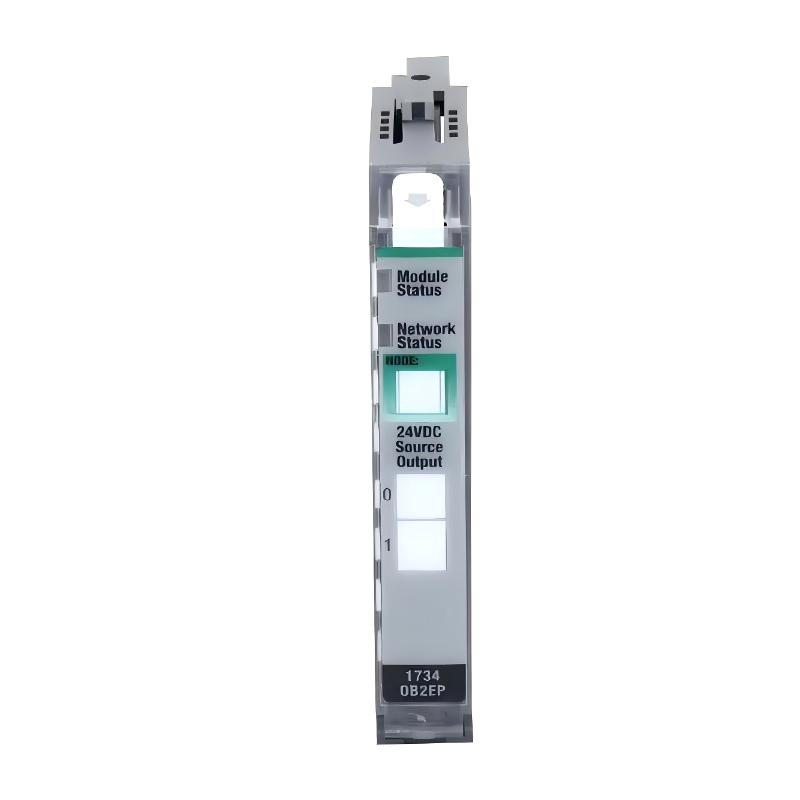
Table of Contents
- 1734-OB2E Digital Output Module Troubleshooting Overview
- Field Case: 1734-OB2E Output Control Failure Analysis
- Common 1734-OB2E Fault Symptoms
- 1734-OB2E Fault Diagnosis Process
- Common Causes of Output Module Failure
- Detailed Troubleshooting Procedure
- Fault Repair and Recovery Actions
- System Verification After Repair
- Frequently Asked Questions
- Engineering Summary
1734-OB2E Digital Output Module Troubleshooting Overview
The Allen-Bradley 1734-OB2E Point I/O 2-Point Digital Output Module Troubleshooting Guide provides a professional maintenance method for diagnosing output failures, wiring problems, communication issues, and configuration errors in industrial automation systems.
The 1734-OB2E is a compact digital output module used in POINT I/O distributed control systems. When the module experiences abnormal operation, engineers need to analyze the complete control path, including controller commands, I/O communication, module status, terminal connections, field power, and connected devices.
A systematic Fault Diagnosis process can quickly identify the root cause and avoid unnecessary module replacement.
Field Case: 1734-OB2E Output Control Failure Analysis
In one automated production line, the control system suddenly lost control of a connected actuator. The PLC program continued operating normally, but the field device did not respond when the output command was activated.
Maintenance engineers checked the 1734-OB2E module status and found no obvious hardware alarm. Further inspection was performed on the complete output circuit.
The investigation showed that the output signal from the controller was correctly transmitted to the module, but the field-side wiring connection had become loose after long-term operation. After reconnecting and tightening the wiring, the actuator returned to normal operation.
This example demonstrates that 1734-OB2E troubleshooting requires checking both the module and external field conditions.
Common 1734-OB2E Fault Symptoms
Typical problems encountered during operation include:
- Output channel cannot switch ON
- Connected device does not respond
- Output indicator status is abnormal
- Controller command exists but no physical output occurs
- Intermittent output operation
- I/O communication alarm appears
- Module status fault indication
These symptoms do not always indicate module damage. Engineers should perform complete diagnosis before replacing hardware.
1734-OB2E Fault Diagnosis Process
A professional troubleshooting process should follow these steps:
- Check PLC output command status
- Verify I/O communication condition
- Check module diagnostic information
- Inspect terminal base connection
- Measure output voltage condition
- Check field device operation
- Confirm system configuration
This process helps determine whether the fault is caused by the controller, network, module, wiring, or external equipment.
Common Causes of Output Module Failure
The main causes of 1734-OB2E output problems include:
- Loose terminal connection
- Incorrect output wiring
- Wrong field power supply
- Damaged actuator or load device
- Incorrect I/O configuration
- Communication interruption
- Terminal base connection problem
- Electrical interference
In industrial environments, external circuit problems are often responsible for output failures rather than internal module faults.
Detailed Troubleshooting Procedure
The recommended troubleshooting procedure is:
- Record the current fault condition
- Check controller output status
- Confirm module communication
- Inspect module installation
- Check terminal wiring
- Measure field output voltage
- Test connected equipment
- Verify normal operation
1734_OB2E_DIAGNOSTIC

MODEL = 1734-OB2E

STEP_01 = CHECK_CONTROLLER_COMMAND
STEP_02 = CHECK_IO_STATUS
STEP_03 = CHECK_TERMINAL_CONNECTION
STEP_04 = CHECK_OUTPUT_SIGNAL
STEP_05 = CHECK_FIELD_DEVICE
Fault Repair and Recovery Actions
After identifying the fault source, engineers can apply the following corrective actions:
- Tighten loose terminal connections
- Correct incorrect wiring
- Restore stable field power
- Repair damaged cables
- Correct controller configuration
- Replace damaged external devices
- Replace the module if hardware failure is confirmed
Most 1734-OB2E problems can be resolved through proper inspection and adjustment without immediate replacement.
System Verification After Repair
After completing maintenance work, engineers should perform final testing:
- Confirm module status is normal
- Test every output channel
- Verify field device response
- Check controller communication
- Monitor operation stability
- Record repair information
Complete verification ensures that the POINT I/O system returns to reliable operation.
Frequently Asked Questions
Why does the 1734-OB2E output channel fail?
Possible reasons include wiring problems, insufficient power, incorrect configuration, communication issues, or external device failure.
How can engineers determine whether the module is damaged?
Engineers should first verify controller commands, wiring, power supply, and field devices before judging module hardware failure.
What is the most common troubleshooting mistake?
Replacing the module immediately without checking external wiring and field conditions can increase maintenance cost and downtime.
Engineering Summary
The Allen-Bradley 1734-OB2E Point I/O 2-Point Digital Output Module Troubleshooting process requires a structured inspection of controller commands, communication status, module condition, wiring connections, field power, and external devices. Accurate Fault Diagnosis helps restore output control quickly, reduce unnecessary replacement costs, and improve the reliability of industrial automation systems.