
NewsNEWCENTER
Featured products



Contact Us
Allen-Bradley 1606-XLS240-UPSC Troubleshooting Guide: Fault Diagnosis, Battery Issues, and Maintenance
2026-10-15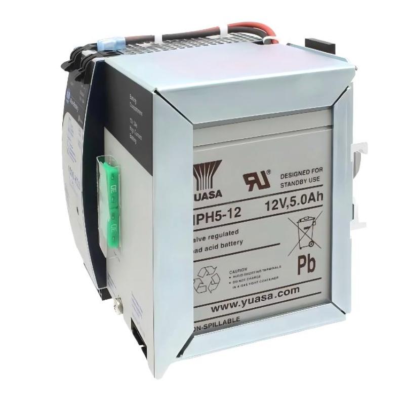
1. Product Overview
The Allen-Bradley 1606-XLS240-UPSC is a 24V DC uninterruptible power supply with an integrated battery, designed to maintain power to selected industrial control loads when the primary DC input is interrupted. It is commonly relevant to applications involving PLCs, automation controllers, control circuits, and other equipment that requires short-term DC power continuity. The 1606-XLS240-UPSC contains an integrated 12V, 5Ah high-current VRLA battery and battery-management functions. Its ability to support connected loads depends on the input supply, load demand, battery condition, temperature, and configured backup behavior. When an Allen-Bradley 1606-XLS240-UPSC develops a fault, the symptoms may include loss of output, unexpected equipment resets, failure to enter buffer mode, a persistent Replace Battery indication, or a warning related to wiring and battery condition. A structured troubleshooting process helps identify whether the problem originates in the upstream DC supply, field wiring, load circuit, battery system, configuration, or the UPS itself.
2. Important Safety Precautions
Before troubleshooting, isolate hazardous energy sources and follow the facility’s lockout/tagout procedures. Verify that the circuit is safe before touching conductors or changing connections. The integrated battery may remain energized even when the primary DC supply is disconnected. Do not assume that removing input power makes all internal battery connections safe. Follow the manufacturer’s battery-isolation procedure before servicing the battery or its fuse. Do not open or attempt component-level repair of the electronic assembly. If internal damage, burning, abnormal heating, or repeated protective shutdowns are observed, remove the unit from service and refer it to qualified personnel or an authorized repair provider. Never bypass protective functions or deliberately overload the output to force a diagnostic response.
3. Common Symptoms and Possible Causes
| Symptom | Possible Causes | Initial Checks |
|---|---|---|
| No expected DC output | Missing input power, incorrect wiring, excessive load, protective shutdown, or internal fault | Measure input voltage, inspect wiring, and check load demand |
| Connected PLC resets during an outage | Battery degradation, excessive load, unsuitable buffer-time setting, or wiring voltage drop | Review battery status, load current, and backup-test results |
| UPS does not enter buffer mode | Input has not crossed the transfer threshold, buffering is inhibited, or a battery/wiring issue exists | Check input behavior, inhibit status, and diagnostic indicators |
| Replace Battery indication | Battery aging, unsuccessful battery test, or a battery connection problem | Review the battery condition and manufacturer’s diagnostic procedure |
| Check Wiring warning | Low or unsuitable input voltage, wiring problem, missing battery connection, or battery-fuse issue | Verify input voltage and inspect battery-related connections after safe isolation |
| Output voltage falls under load | Overload, excessive startup current, poor connections, or unsuitable input conditions | Measure voltage under load and compare demand with permitted limits |
| Frequent buffering events | Unstable primary DC supply, undersized upstream supply, or intermittent wiring | Monitor the input voltage and inspect upstream power connections |
These are diagnostic possibilities rather than proof of a specific failure. Interpret each symptom using the status indicators, measured operating conditions, and documentation for the exact catalog number.
4. Troubleshooting a No-Output Condition
4.1 Verify the Primary DC Input
Start by confirming that the upstream supply is operating and that the DC voltage reaching the UPS is within the specified continuous input range of 22.5–30V DC. A supply may show an acceptable voltage when disconnected but drop excessively when the load is applied. Where the approved test procedure permits, compare the input voltage under normal operating conditions with the voltage at the upstream source. A significant difference may indicate excessive conductor resistance, a loose connection, or an upstream supply problem. Do not disconnect live conductors or probe exposed terminals without the required training, protective measures, and approved test procedure.
4.2 Inspect Input and Output Wiring
If the input voltage is correct, isolate the system and inspect the power connections. Confirm polarity, terminal security, conductor condition, and the correspondence between input and output wiring and the manufacturer’s diagram. Look for loose conductors, damaged insulation, corrosion, discoloration, or evidence of overheating. Correct any external wiring defects before restoring power.
4.3 Check the Connected Load
A load that exceeds the permitted output capability can cause output voltage reduction or protective behavior. Check the combined load current, including startup surges and transient demand. If the approved maintenance procedure permits load isolation, identify whether the problem is associated with a particular downstream circuit. Do not disconnect critical equipment while the process is running unless the operational risk has been evaluated and approved. If the output remains abnormal after input power, wiring, and load demand have been verified, the UPS may require qualified inspection or replacement.
5. Troubleshooting Battery and Backup Problems
5.1 UPS Does Not Maintain Power During an Input Failure
If the connected PLC or other critical equipment loses power when the primary input fails, investigate the battery system and the conditions under which buffering is expected to occur. Possible causes include:
- The battery has reached the end of its service life.
- The battery connection or battery fuse has a problem.
- The load current is too high for the required backup duration.
- The buffer-time limiter is set to a shorter period than the application requires.
- The inhibit input is active or the configured system logic prevents buffering.
- The output wiring or downstream equipment has a separate fault.
Check the status indicators and the inhibit state first. If battery-related warnings are present, follow the manufacturer’s diagnostic procedure before replacing the battery.
5.2 Replace Battery Indication
A Replace Battery indication should be treated as a maintenance warning that requires investigation. Battery degradation may reduce the amount of energy available during a power interruption even when normal operation appears unaffected. Review the battery installation date, service history, environmental temperature, and frequency of backup events. Check for a documented battery-test failure and follow the manufacturer’s instructions for confirming battery condition. If replacement is required, use a battery that meets the specified voltage, capacity, terminal, and other applicable requirements. Do not substitute a battery based on physical size alone.
5.3 Check Wiring or Battery Warning
The unit’s diagnostic system can identify certain wiring and battery conditions. A warning may be associated with unsuitable input voltage, an incorrect or poor battery connection, or a missing or failed battery fuse. First confirm that the primary input is within the permitted range. Then isolate the unit according to the approved procedure before inspecting battery-related wiring or the fuse. Never remove or insert the battery fuse while ignoring the manufacturer’s safety sequence. Battery terminals may remain energized, and an accidental short circuit can produce high current and serious injury.
5.4 Backup Duration Is Shorter Than Expected
Backup time varies with load current, battery age, temperature, battery condition, and the operating mode. A battery that has deteriorated may support normal operation but provide significantly less runtime during an outage. Check the actual load current and compare it with the intended design. Review the buffer-time limiter setting and look for noncritical devices that may be unnecessarily consuming backup energy. Conduct a controlled runtime test only when the connected process can tolerate it. Record the load, test duration, battery status, and shutdown behavior so that future tests can be compared consistently.
6. Troubleshooting Output Voltage Instability
6.1 Measure Input and Output Conditions
If the output voltage fluctuates, establish whether the variation follows changes in the primary input, changes in load demand, or a transition into buffer mode. Record the input voltage and output behavior under representative operating conditions. Compare measurements with the technical data for the installed catalog number and operating mode. Do not apply one fixed output-voltage expectation to all conditions. Normal mode and buffer mode can have different output characteristics, and the permitted current may differ between them.
6.2 Investigate Overload and Startup Demand
A load with a high startup current may cause an otherwise acceptable system to experience voltage reduction or intermittent resets. Review the electrical requirements of connected PLCs, relays, communication devices, and other equipment. Where appropriate, separate noncritical loads from buffered loads and reassess the total demand. Any changes must preserve the required control and safety functions.
6.3 Check Connections and Conductors
Poor connections and undersized conductors can create voltage drops that become more pronounced under load. Inspect wiring only after following the appropriate isolation procedures. If the wiring is sound and the load remains within the permitted range but instability continues, the unit may require further evaluation by qualified service personnel.
7. Troubleshooting Status Indicators and Signal Contacts
The 1606-XLS240-UPSC provides status functions associated with Ready, Buffering, Replace Battery, and Inhibit. These signals can help identify the operating state, but their meaning must be interpreted according to the manufacturer’s definitions.
7.1 Ready Status Is Not Present
A missing Ready indication may be related to insufficient input voltage, battery charge state, a detected wiring issue, or an active inhibit condition. Check the primary DC input and review the other diagnostic indicators. Confirm the inhibit signal state and inspect the system’s signal wiring against the approved diagram. Do not assume that a single status contact proves that every downstream load is healthy.
7.2 Buffering Status Does Not Change
If Buffering does not indicate a backup event, confirm whether the input voltage has actually crossed the unit’s transfer threshold and whether buffering is permitted by the configured system state. A status contact may also be wired incorrectly or interpreted incorrectly by the PLC program. Verify the signal-contact configuration and PLC input logic before concluding that the UPS electronics have failed.
7.3 PLC Reports an Incorrect UPS Alarm
When the PLC alarm disagrees with the front-panel indicators, inspect the signal wiring, input configuration, logic polarity, and alarm timing. Check whether the PLC expects a normally open or normally closed contact as defined by the actual circuit design. Do not change control logic simply to suppress an alarm. Establish the cause and verify the intended response before modifying the program.
8. Battery Replacement and Service Decisions
Battery replacement should be performed by qualified personnel in accordance with the manufacturer’s instructions. The replacement battery must satisfy the required electrical and mechanical specifications. A safe service process includes:
- Place the controlled process in an approved maintenance state.
- Isolate the primary DC supply and apply lockout/tagout procedures.
- Follow the specified procedure to disconnect the battery fuse.
- Verify the safe condition of the equipment before handling connections.
- Replace the battery with an approved compatible type and observe polarity.
- Reassemble the battery compartment and restore the fuse according to the manufacturer’s sequence.
- Restore the primary supply and check diagnostic indications.
- Perform an approved functional test and record the service action.
Do not open the electronic assembly or attempt board-level repair. If the unit shows signs of internal damage, repeated protective shutdowns, abnormal heating, or persistent faults after external wiring and battery checks, remove it from service for qualified evaluation.
9. Preventive Maintenance Recommendations
A preventive maintenance plan can reduce unexpected UPS failures and improve the reliability of the control system.
9.1 Routine Visual Inspection
Inspect the enclosure, mounting, wiring, and surrounding ventilation area. Look for dust buildup, moisture, corrosion, damaged conductors, or signs of overheating. Correct environmental issues before they affect the battery or electronic components.
9.2 Battery Condition Monitoring
Maintain a record of battery installation dates, replacement dates, warning events, and backup-test results. Battery service life depends on environmental temperature and charge/discharge history, so use the manufacturer’s guidance and actual operating conditions to determine replacement intervals.
9.3 Controlled Functional Testing
Test backup operation at a planned interval appropriate for the process and maintenance policy. Confirm that critical loads remain powered as expected, the status signals change correctly, and normal operation resumes when the primary input returns. Avoid unnecessary repeated discharge tests, which can contribute to battery wear. Ensure that each test has an approved procedure and a documented expected result.
9.4 Review Upstream Power Quality
Frequent buffering may indicate that the primary DC source or upstream distribution system is unstable. Investigate repeated input-voltage drops, intermittent connections, or excessive demand on the upstream supply rather than treating every buffering event as a UPS failure.
10. Frequently Asked Questions
Why does the Allen-Bradley 1606-XLS240-UPSC show a battery warning?
Possible causes include battery aging, an unsuccessful battery test, or a battery connection problem. Check the diagnostic indicators and service history, then follow the model-specific battery inspection procedure.
Can the integrated battery be replaced?
Yes. The battery is a service item, but replacement should be performed by qualified personnel using a compatible battery and the manufacturer’s prescribed isolation and installation sequence.
Why does the connected PLC restart during a power interruption?
Possible causes include insufficient battery capacity, excessive load, a short buffer-time setting, voltage drop in the wiring, or an issue with the downstream circuit. Check the complete power path rather than assuming the UPS itself is defective.
What should be done if the output remains unstable after checking the load?
Verify the input voltage, polarity, wiring integrity, load current, and diagnostic status. If the problem persists with external conditions verified, refer the unit for qualified evaluation or replace it according to the site’s maintenance procedure.
Can the UPS be operated with the battery disconnected?
Do not assume that operation without the battery is acceptable for the application. Follow the manufacturer’s instructions and the approved maintenance procedure; the intended backup function cannot be relied upon when the battery is unavailable.
11. Technical Summary
Troubleshooting the Allen-Bradley 1606-XLS240-UPSC requires a systematic review of primary DC input, power wiring, load demand, integrated battery condition, buffer-time configuration, and status signals. A no-output condition does not automatically indicate internal failure, and a short backup duration may reflect battery aging or excessive load rather than a defective electronic assembly. Always isolate hazardous energy before service, remember that the integrated battery may remain energized, and avoid unauthorized internal repairs or bypasses of protective functions. Documented preventive maintenance, controlled backup testing, and timely battery replacement help maintain dependable DC power continuity for industrial automation equipment.