
NewsNEWCENTER
Featured products



Contact Us
Allen-Bradley 1606-XLS240-UPSC Power Supply Installation Guide: Wiring, Setup, and Commissioning
2026-10-15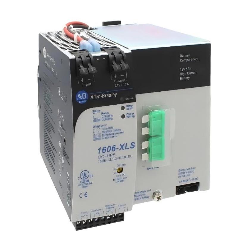
1. Product Overview
The Allen-Bradley 1606-XLS240-UPSC is a 24V DC uninterruptible power supply (DC-UPS) with an integrated battery, designed to maintain power to essential industrial control equipment during temporary interruptions of the primary DC supply. It is part of the Allen-Bradley 1606 power supply product family and is suitable for control cabinets that require dependable power continuity for PLCs, automation controllers, instrumentation, and other critical DC loads. Unlike the Allen-Bradley 1606-XLS240-UPS model, which uses an external battery arrangement, the 1606-XLS240-UPSC incorporates a 12V, 5Ah high-current battery. Its internal battery management system monitors charging and battery condition to support reliable backup operation. Correct installation of the Allen-Bradley 1606-XLS240-UPSC power supply involves more than connecting the input and output terminals. Engineers must also check the DC input voltage, separate buffered and non-buffered loads, verify battery protection, configure the buffer-time limiter, and test the diagnostic signals before commissioning.
2. Technical Specifications
| Parameter | Specification |
|---|---|
| Manufacturer | Allen-Bradley / Rockwell Automation |
| Model | 1606-XLS240-UPSC |
| Product type | DC uninterruptible power supply with integrated battery |
| Nominal input voltage | 24V DC |
| Continuous input voltage range | 22.5–30V DC |
| Output voltage | Depends on operating mode and load; nominally near the 24V DC control-system level |
| Output current | Operating-mode dependent; consult the exact technical manual for continuous and buffer-mode limits |
| Integrated battery | 12V, 5Ah high-current VRLA lead-acid battery |
| Typical operating temperature | 0–40°C at full output power |
| Mounting | 35 mm DIN rail |
| Protection functions | Includes electronic output protection and battery-related protection functions |
The exact allowable output current depends on whether the unit is operating in normal mode or buffer mode. Do not select conductors, protective devices, or connected loads based solely on the model’s nominal power class. Confirm all operating limits and terminal assignments in the documentation matching the installed catalog number.
3. Installation Preparation
3.1 Verify the Model and Electrical Ratings
Before installing the Allen-Bradley 1606-XLS240-UPSC, check the product label and confirm that the catalog number ends in UPSC. This suffix identifies the version with an integrated battery. Similar models may use different battery arrangements or have different installation requirements. Review the following items before beginning work:
- Confirm that the primary DC source is compatible with the 22.5–30V DC input range.
- Calculate the steady-state current and peak current requirements of the connected equipment.
- Identify which loads require uninterrupted power during a supply failure.
- Confirm the required backup duration under the expected load.
- Inspect the enclosure, DIN rail, conductors, protective devices, and grounding arrangements.
- Verify the signal-terminal assignments against the product’s official wiring diagram.
3.2 Prepare the Control Cabinet
Install the DC-UPS on a suitable 35 mm DIN rail in an industrial control cabinet. The power terminals should be oriented as specified by the manufacturer, and sufficient space must remain around the enclosure for heat dissipation and service access. Allow airflow around the unit. Avoid installing it directly beside equipment that generates substantial heat, particularly where that heat could raise the integrated battery temperature. Do not install the unit in an airtight enclosure without an appropriate thermal-management design. The specified full-power operating temperature range is 0–40°C. If the cabinet routinely exceeds this range, reassess the installation location and thermal conditions before commissioning.
3.3 Apply Electrical Safety Procedures
Before wiring, isolate the primary DC supply and apply the site’s lockout/tagout procedure. Verify the absence of hazardous voltage using an appropriate instrument. The integrated battery requires additional care because battery terminals can remain energized even when the primary DC input has been disconnected. Follow the manufacturer’s battery-isolation procedure before working on the battery or its connections. Do not place tools or conductive objects across battery terminals.
4. Wiring the Allen-Bradley 1606-XLS240-UPSC
4.1 Understand the Power Connections
The unit provides power terminals for the DC input and the protected output. The exact terminal positions and markings must be confirmed on the installed unit and in the matching wiring diagram. The basic system arrangement is:
24V DC Primary Supply
          |
          v
Allen-Bradley 1606-XLS240-UPSC
          |
          +---- Buffered DC Output ---- Critical Loads
          |
          +---- Status and Control Signals
This is an illustrative functional arrangement, not a terminal-level wiring diagram. It does not specify individual terminal numbers or conductor sizes.
4.2 Connect the Primary DC Supply
Confirm the polarity and measured voltage of the primary DC source before connecting it to the UPS input. The input must remain within the permitted continuous operating range. Use conductors suitable for the expected current, cabinet temperature, routing method, and applicable electrical regulations. Tighten or secure connections according to the terminal design and the manufacturer’s instructions. Inspect the wiring to ensure that no strands are loose and that insulation is not trapped incorrectly. Do not energize the unit if the input voltage is unstable, the polarity is uncertain, or the wiring does not match the approved diagram.
4.3 Connect the Buffered Load
Connect the equipment that requires backup power to the designated UPS output. Typical loads may include PLC controllers, industrial communication equipment, essential sensors, and control circuits that must remain energized long enough for an orderly shutdown or controlled response. Separate noncritical loads from the buffered circuit where the system design permits. This reduces unnecessary battery discharge and reserves available energy for essential equipment. Before connecting the full load, check the current demand of all buffered devices. Account for startup surges, switching loads, and any equipment that could exceed the UPS output capability during a transient.
4.4 Connect Monitoring and Inhibit Signals
The 1606-XLS240-UPSC includes signal connections associated with Ready, Buffering, Replace Battery, and Inhibit functions. These signals can be used to communicate UPS status to a PLC or another monitoring system. Use the manufacturer’s signal wiring diagram to identify the correct contacts and electrical characteristics. Do not assume that the status connections can be wired directly to every PLC input without checking voltage, current, isolation, and circuit requirements. The Ready signal can help indicate whether the unit’s operating conditions are suitable, while Buffering identifies backup operation and Replace Battery indicates a battery-related maintenance condition. The Inhibit input can affect buffering behavior and should only be used when the system design explicitly requires it.
5. Integrated Battery and Buffer-Time Configuration
The integrated 12V, 5Ah high-current VRLA battery is an important part of the 1606-XLS240-UPSC design. The UPS uses its battery-management functions to charge and monitor the battery and to support backup operation when the input voltage falls below the transfer threshold. The actual backup duration depends on load current, battery condition, temperature, battery age, and the operating conditions during the outage. A published or historical typical backup time should not be treated as a guaranteed runtime for every installation. The unit includes a buffer-time limiter that can restrict the duration of backup operation. Select a setting that supports the required control-system response while avoiding unnecessary battery discharge. The available settings and their behavior should be checked against the exact manual revision. For a system that must preserve PLC state or complete a controlled shutdown, determine the minimum runtime needed by testing the real load rather than relying only on theoretical estimates.
6. Commissioning Procedure
6.1 Pre-Power Inspection
Before energizing the primary supply, complete the following checks:
- Confirm the catalog number and input voltage rating.
- Verify input and output polarity.
- Inspect the DIN-rail mounting and cabinet ventilation.
- Check the load-current calculation against the permitted operating limits.
- Confirm that the integrated battery and battery fuse are installed according to the manufacturer’s procedure.
- Verify that status and inhibit wiring follows the approved diagram.
- Check that no tools, loose conductors, or foreign objects remain inside the enclosure.
6.2 Energize the Primary Supply
Restore the primary DC supply in accordance with the commissioning plan. Measure the input voltage at the unit and confirm that it remains within the permitted range. Observe the status indicators and check for wiring or battery warnings. Do not proceed to full-load testing if a fault indicator remains active or the measured voltage is outside the permitted range. Investigate the cause before continuing.
6.3 Verify Normal Output Operation
Measure the output voltage under the expected load and compare it with the manufacturer’s operating characteristics. Confirm that connected control equipment starts correctly and that no unexpected resets, alarms, or communication interruptions occur. Check that the total load remains within the permitted current and power limits. If the output voltage drops significantly under load, investigate the input supply, wiring resistance, load demand, and possible overload conditions.
6.4 Test Backup Operation
Only perform a backup test when the system can safely tolerate temporary loss of the primary DC input. Notify affected personnel and place the controlled process in an approved test state. Interrupt the primary input using the approved isolation method while observing the buffered output and connected equipment. Confirm that critical loads remain powered and that the Buffering status changes as expected. Restore the primary supply and verify that normal operation resumes, the battery begins recharging as appropriate, and the status indicators return to the expected state.
6.5 Document Commissioning Results
Record the input voltage, output voltage under load, connected load current, buffer-time setting, status-indicator behavior, and backup-test results. Include the date, product catalog number, and any battery replacement information in the maintenance record.
7. Integration with Industrial Control Systems
The Allen-Bradley 1606-XLS240-UPSC can be incorporated into industrial control cabinets where short-term DC power continuity is required. In a PLC panel, it may support the controller and selected control circuits during a temporary input interruption. When integrating the unit with a PLC or HMI, decide which loads need backup and which can be allowed to shut down. Avoid connecting every cabinet load to the buffered output without checking total demand and required runtime. Status signals can be incorporated into the control program to support alarms, event logging, or maintenance notifications. The control logic should distinguish between a temporary buffering event and a battery-maintenance warning. Any automatic shutdown response must be validated against the process safety requirements.
8. Preventive Maintenance
The integrated battery has a finite service life. Temperature, age, discharge frequency, and charging conditions influence battery performance. Establish a battery inspection and replacement schedule based on the manufacturer’s recommendations and the actual environment. Periodic maintenance should include:
- Checking status indicators and monitoring alarms.
- Inspecting the enclosure for dust, moisture, damage, and blocked ventilation.
- Reviewing event logs for repeated buffering or battery warnings.
- Testing backup performance under controlled conditions.
- Inspecting battery condition and replacing it when required.
- Recording maintenance actions and verifying operation after service.
Battery replacement must be performed by qualified personnel using a compatible battery that meets the manufacturer’s requirements. Follow the prescribed isolation procedure and observe battery polarity. Do not open or repair internal electronic circuits.
9. Frequently Asked Questions
What is the Allen-Bradley 1606-XLS240-UPSC used for?
It is a 24V DC UPS with an integrated battery that helps maintain power to selected industrial control loads during temporary interruptions of the primary DC supply.
Does the 1606-XLS240-UPSC include a battery?
Yes. This model incorporates a 12V, 5Ah high-current VRLA battery. Confirm the condition and installation of the battery before commissioning a new or stored unit.
Can all 24V DC loads be connected to the buffered output?
Not automatically. The combined steady-state current, startup demand, output limits, and required backup duration must be evaluated before connecting loads.
How can the backup duration be increased?
The available runtime is determined by the model’s battery arrangement and operating conditions. For this integrated-battery version, follow the manufacturer’s approved battery and configuration guidance. Do not modify the battery arrangement without explicit authorization.
What should be checked if the UPS does not enter buffer mode?
Check the primary input conditions, battery status, wiring and battery-fuse condition, inhibit state, and diagnostic indicators. Use the exact model’s troubleshooting instructions before replacing components.
10. Technical Summary
The Allen-Bradley 1606-XLS240-UPSC is an integrated-battery 24V DC UPS designed to improve power continuity for essential industrial control loads. Successful installation depends on correct input wiring, suitable load selection, proper battery protection, adequate ventilation, and verification of status signals. A disciplined commissioning process should confirm normal output operation, backup transition, battery monitoring, and recovery after input power returns. Regular inspection and planned battery maintenance help preserve the reliability of the UPS and the industrial equipment it supports.