
NewsNEWCENTER
Featured products
Contact Us
Allen Bradley 1606-XLBUFFER Power Supply Troubleshooting Guide
2026-08-25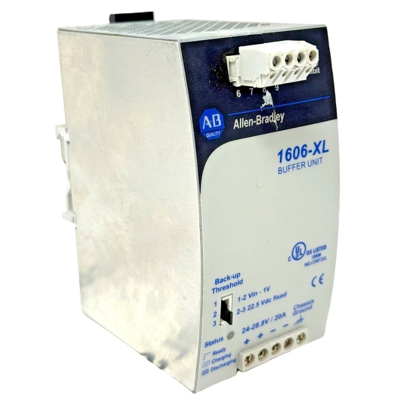
Table of Contents
- Allen Bradley 1606-XLBUFFER Troubleshooting Problem Definition
- Allen Bradley 1606-XLBUFFER Fault Symptoms
- Allen Bradley 1606-XLBUFFER Power-System Fault Boundaries
- Allen Bradley 1606-XLBUFFER Fault Diagnosis Measurements
- Common Allen Bradley 1606-XLBUFFER Fault Causes
- Allen Bradley 1606-XLBUFFER Buffering Performance Investigation
- Allen Bradley 1606-XLBUFFER Real Fault Diagnosis Case
- Allen Bradley 1606-XLBUFFER Repair and Replacement Strategy
- Allen Bradley 1606-XLBUFFER Post-Repair Testing
- Allen Bradley 1606-XLBUFFER Troubleshooting FAQ
- Allen Bradley 1606-XLBUFFER Overall Fault Diagnosis Summary
Allen Bradley 1606-XLBUFFER Troubleshooting Problem Definition
Allen Bradley 1606-XLBUFFER troubleshooting should begin by defining exactly what failed: the upstream DC source, the buffer function, the downstream distribution, or the protected PLC load. A PLC Controller reset during a power disturbance does not automatically mean that the 1606-XLBUFFER is defective.
In practical Fault Diagnosis, the timing of the failure is often the most useful first clue. A problem that occurs only during an input interruption requires a different diagnostic approach from a problem that occurs continuously during normal operation.
Allen Bradley 1606-XLBUFFER Fault Symptoms
Typical symptoms associated with an abnormal buffered DC system can include:
- PLC Controller resets during a supply disturbance.
- Remote I/O Modules temporarily disappear.
- Communication interfaces restart.
- Sensors produce invalid or intermittent signals.
- Control relays drop out unexpectedly.
- Buffered loads remain stable for a short period and then lose power.
- The control system fails to recover normally after input power returns.
- The fault occurs only when the buffered load is near its normal operating level.
Allen Bradley 1606-XLBUFFER Intermittent Fault Clues
If the fault occurs only when several loads operate together, record which loads are active at that exact moment. If the fault appears after a specific duration of an input interruption, compare that duration with the expected power-system design rather than assuming immediate hardware failure.
Allen Bradley 1606-XLBUFFER Power-System Fault Boundaries
A useful way to troubleshoot the 1606-XLBUFFER is to divide the circuit into three main boundaries: upstream source, buffering section, and downstream protected load. Each boundary can be tested independently.
FAULT BOUNDARY ANALYSIS

UPSTREAM
DC source
   |
   v
BUFFER
1606-XLBUFFER
   |
   v
DISTRIBUTION
   |
   v
PLC / I/O / Sensor

Question 1:
Is the input source stable?

Question 2:
Does the buffer maintain the expected DC condition?

Question 3:
Does the protected load receive stable voltage?

Question 4:
Does the load remain within the intended configuration?
This approach avoids confusing the power-buffering device with the entire DC system. A fault downstream of the buffer can produce exactly the same PLC symptom as a defective buffer.
Allen Bradley 1606-XLBUFFER Fault Diagnosis Measurements
Measurement should be performed under the condition that produces the fault. If the problem occurs during an input interruption, measurements taken only while the supply is healthy may provide very limited diagnostic value.
Useful measurement points include the upstream DC source, the buffer terminals, the main protected DC bus, and the supply point of the affected PLC or Module.
Allen Bradley 1606-XLBUFFER Diagnostic Measurement Pattern
- Measure the normal upstream DC voltage.
- Measure the normal buffer output.
- Measure the protected DC bus.
- Measure the affected load.
- Repeat measurements during the fault condition.
- Compare results against the commissioning baseline.
If the buffer output remains stable but a remote load drops significantly, the investigation should move toward distribution wiring and load conditions. If the abnormal condition is already present at the buffer output, the upstream source, buffer, or load interaction requires further examination.
Common Allen Bradley 1606-XLBUFFER Fault Causes
- Excessive buffered load: too many devices may be connected to the protected circuit.
- Unexpected load increase: later system modifications can change the original power calculation.
- High-resistance connection: loose or deteriorated terminals can cause transient voltage drops.
- Downstream short circuit: a damaged cable or failed field device can affect the protected DC bus.
- Incorrect System Configuration: a circuit may have been connected to the buffered output without considering its current demand.
- Upstream supply problem: an abnormal input condition can prevent correct buffering behavior.
- Thermal stress: cabinet temperature can influence the behavior of power equipment.
Allen Bradley 1606-XLBUFFER Buffering Performance Investigation
When the primary complaint is insufficient ride-through, do not immediately conclude that the buffer has failed. First determine the actual load and the duration of the interruption that caused the PLC to reset.
For example, if the PLC remains online during a short interruption but resets when the interruption lasts longer, the event may reflect the boundary of the intended buffering capability rather than an intermittent hardware fault. Conversely, if the PLC resets during an interruption that should be supported by the configured system, further investigation is warranted.
Allen Bradley 1606-XLBUFFER Ride-Through Investigation
- Document the normal DC load.
- Identify the equipment connected to the buffered bus.
- Determine the approximate interruption condition.
- Observe the buffer and load-side voltage.
- Check whether the PLC resets at a repeatable point.
- Investigate load changes and downstream connections.
- Compare the result with the intended System Configuration.
Allen Bradley 1606-XLBUFFER Real Fault Diagnosis Case
In one industrial automation case, a PLC Controller restarted during short incoming-power disturbances. The maintenance team initially suspected the 1606-XLBUFFER because the PLC was specifically connected to the buffered DC circuit.
The first measurement showed a normal DC condition during steady-state operation. The engineer then reproduced the approved interruption test and monitored both the buffer output and the PLC supply point.
The buffer output remained within the expected behavior, but the PLC supply point experienced a transient drop. A comparison with the electrical drawing showed that an additional communication device had been connected to the same protected branch during a later system modification.
The additional load had not been included in the original commissioning baseline. When the incoming supply disappeared, the total buffered demand was higher than the original design condition.
The engineer temporarily isolated the added branch and repeated the test. The PLC remained stable during the same disturbance. This narrowed the investigation to the changed load configuration rather than the buffer itself.
After the control-power architecture was revised according to the engineering requirements, the system was retested. The PLC and critical I/O equipment operated normally during the intended disturbance test.
The lesson is straightforward: when buffering performance changes after a cabinet modification, investigate the changed load configuration before replacing the buffer.
Allen Bradley 1606-XLBUFFER Repair and Replacement Strategy
Repair or replacement should follow Fault Diagnosis rather than precede it. First determine whether the abnormal behavior follows the 1606-XLBUFFER or remains with a particular downstream circuit.
If the upstream source is correct, the load has been verified, distribution wiring is healthy, and the buffer itself produces abnormal behavior under a controlled test, replacement can be considered according to the maintenance procedure.
Allen Bradley 1606-XLBUFFER Corrective Actions
- Correct incorrect DC wiring.
- Repair high-resistance connections.
- Remove inappropriate loads from the buffered circuit.
- Correct branch protection issues.
- Investigate abnormal upstream power conditions.
- Replace the buffer only after external causes have been excluded.
Do not bypass protective devices or modify the buffering architecture simply to make the PLC remain online. Any change to a critical control-power system should be reviewed against the approved electrical design.
Allen Bradley 1606-XLBUFFER Post-Repair Testing
After corrective work, the original failure sequence should be repeated. If the original fault involved a brief interruption, perform the approved interruption test again. If it involved a high-load operating condition, reproduce that load condition as well.
Allen Bradley 1606-XLBUFFER Recovery Verification
- Confirm normal input power.
- Confirm normal buffer output.
- Verify the protected DC distribution.
- Check PLC Controller stability.
- Check I/O Module availability.
- Check communication recovery.
- Repeat the original disturbance condition.
- Document final measurements.
A successful Repair is demonstrated by stable operation under the original failure condition, not simply by the absence of an alarm after a power cycle.
Allen Bradley 1606-XLBUFFER Troubleshooting FAQ
Why does the PLC reset even though the Allen Bradley 1606-XLBUFFER appears normal?
The buffer may be operating correctly while the downstream distribution or load condition is abnormal. A voltage measurement at the PLC supply point during the actual disturbance can help identify whether the problem is upstream or downstream.
Can excessive load reduce buffering performance?
Yes. The actual buffered load directly affects the behavior of a DC power system during an interruption. Additional PLC, communication, I/O, or other loads can change the original operating condition.
What should be checked when the 1606-XLBUFFER fault is intermittent?
Check the timing of the fault, input condition, buffer output, load-side voltage, connected load changes, terminal condition, and cabinet temperature. Reproduce the failure whenever possible.
Should the 1606-XLBUFFER be replaced after a single PLC reset?
No. A single PLC reset is insufficient evidence of buffer failure. The complete power path should be investigated and measurements should be compared with the intended System Configuration.
How can maintenance engineers improve future 1606-XLBUFFER Fault Diagnosis?
Keep a commissioning baseline containing normal DC measurements, connected-load information, PLC and I/O status, and results from approved disturbance tests. Future Troubleshooting can then compare current behavior against a known operating condition.
Allen Bradley 1606-XLBUFFER Overall Fault Diagnosis Summary
Allen Bradley 1606-XLBUFFER Troubleshooting requires a system-level approach. A PLC Controller reset or I/O communication fault may originate from the buffer, but it can also be caused by excessive buffered load, poor DC distribution, an upstream disturbance, or a later change to the System Configuration.
The most reliable Fault Diagnosis method is to establish a baseline, reproduce the fault, measure the power system at multiple boundaries, isolate the affected load, and determine where the electrical condition changes. This evidence-based approach prevents unnecessary replacement of healthy equipment.
After Repair or corrective action, repeat the original operating condition and record the final results. A properly documented baseline makes future Installation, Setup, Commissioning, Troubleshooting, and maintenance of the Allen Bradley 1606-XLBUFFER power system considerably more efficient.