

ProductPRODUCT
Featured products
Contact Us
- Allen Bradley
- 1492-TAIFM16-F-3
- Fused Termination Module
- USA
- 120 × 80 × 40 mm
- 0.31 kg
- Xiamen, China
- New & In Stock
- T/T, PayPal, Western Union
- 1 Year
- 1-3 Working Days
- DHL, UPS, TNT, FedEx and EMS.
- 24-Hour Service
- COO
- 4
Our advantage

Global Logistics
We have a 10-year logistics and express cooperation agreement, so our products can be shipped to any place in the world.

Brand new and original
Our products are imported in bulk from the place of origin. Because of the cooperative relationship, our products are all original and 100% new.

24-hour service
We provide 7*24 hours service to our customers. We will be there whenever you need us.

Price advantage
All our products are priced very favorably because we have our own warehouse and supply.
| Company Information | |||
| [email protected] | |||
| Mobile | +8615980777398 | ||
| +8615980777398 | |||
| 15980777398 |
Product Overview
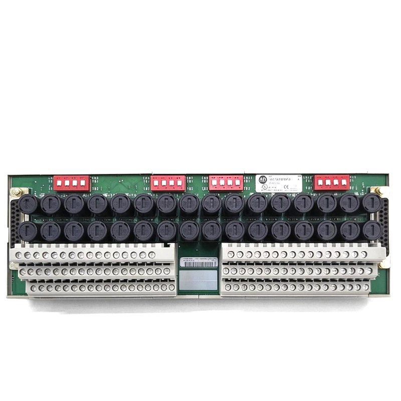
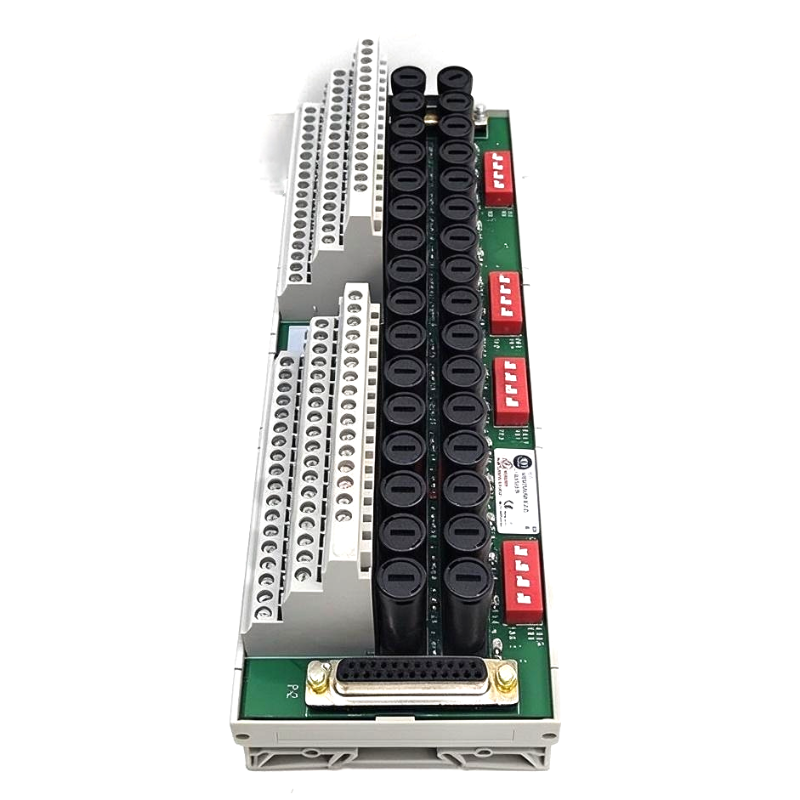
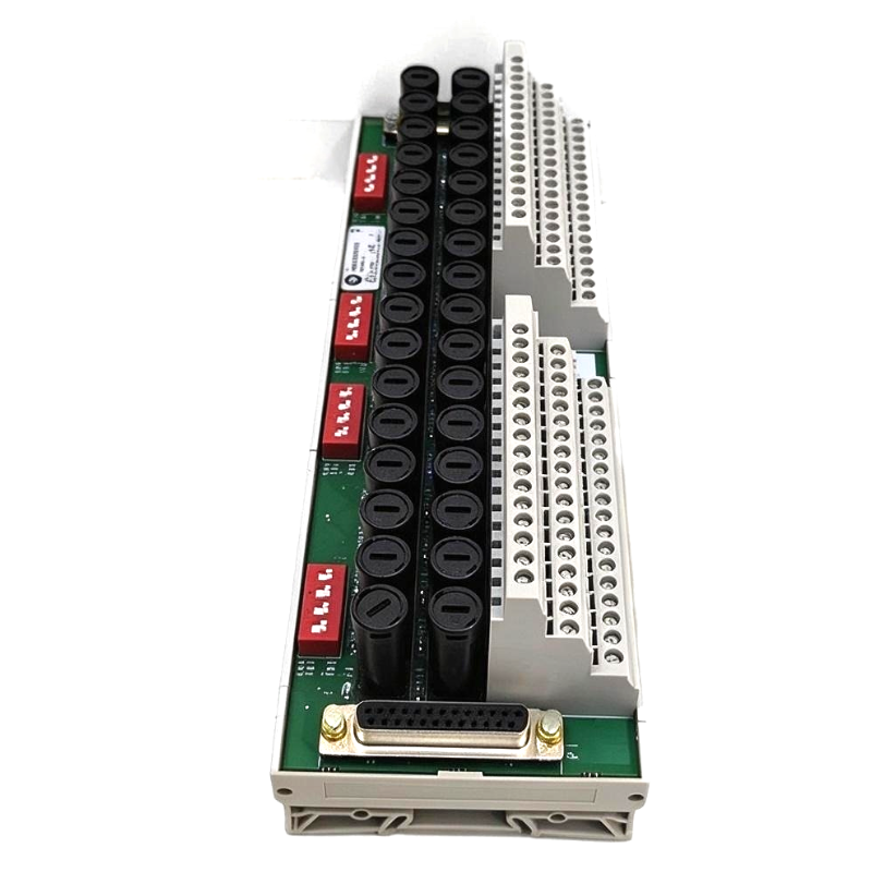
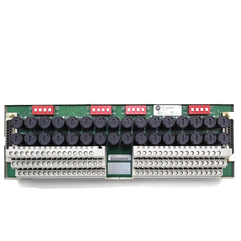
The Allen Bradley 1492-TAIFM16-F-3 Fused Termination Module is an analog input wiring interface used with ControlLogix 1756-IF16 analog input modules. It combines field-side signal termination, individual input-circuit fusing, and blown-fuse indication in a single assembly. This arrangement is particularly useful in process control cabinets where analog signals from transmitters must be distributed to the controller while maintaining organized wiring and a means of identifying fuse failures.
In a typical process installation, pressure transmitters, flow meters, level instruments, and other measurement devices send electrical signals to a ControlLogix controller. The 1492-TAIFM16-F-3 provides the connection between the field wiring and the associated analog input modules. Its terminal arrangement accommodates the signal conductors, common connections, and shield wiring needed to bring the instrument signals into the control system.
The module supports a configuration using two 1756-IF16 analog input modules. Its built-in fuse holders protect the designated input circuits, while the 24V DC blown-fuse indicators help maintenance personnel identify a circuit in which a fuse has operated. This makes troubleshooting more direct when an instrument signal disappears or an input circuit no longer behaves as expected.
A useful feature is its selectable wiring arrangement. DIP switches allow the interface to be configured for 16 SIL 2 sensors or 32 standard sensors, with the factory default set for 16 SIL 2 sensors. These arrangements use different wiring configurations, so the switch settings and terminal assignments must correspond to the intended application. The number of supported sensors should not be confused with the number of physical channels available on a single 1756-IF16 module.
The interface is intended for specific analog signal types. The associated 1756-IF16 module must be configured for 4–20 mA current-loop signals or supported 5V DC input signals in this application. A 0–10V signal source is not appropriate for this interface arrangement and can lead to premature module failure. This distinction matters when selecting transmitters or replacing instruments during a plant upgrade.
The 1492-TAIFM16-F-3 also incorporates grouped shield terminals and field-side connections that help reduce the need for separate terminal blocks and jumper wiring. Proper shield termination is especially relevant in cabinets containing variable-frequency drives, motor contactors, and other equipment that can introduce electrical interference into low-level analog signals.
For maintenance teams, the combination of circuit fusing and visual fuse indication can help narrow down faults without immediately replacing an entire interface assembly. However, a blown-fuse indicator only identifies a fuse-related condition; it does not determine whether the underlying cause is a short circuit, damaged field wiring, an incorrectly connected instrument, or another electrical problem. The affected circuit should be inspected before a replacement fuse is installed.
Technical Specifications
| Parameter | Specification |
|---|---|
| Manufacturer | Allen-Bradley |
| Model | 1492-TAIFM16-F-3 |
| Product Type | Fused Termination Module with Blown-Fuse Indication |
| Product Family | Bulletin 1492 Wiring Systems |
| Compatible I/O Platform | ControlLogix Bulletin 1756 |
| Compatible Analog Input Modules | Two 1756-IF16 modules |
| Analog Input Configuration | Single-ended voltage mode for the specified interface application |
| Channel Arrangement | 16 SIL 2 sensors or 32 standard sensors, according to DIP switch configuration |
| Fuse Arrangement | 32 fuse holders |
| Fuse Indication | 24V DC blown-fuse indicators |
| Nominal Operating Voltage | 24V DC |
| Specified Operating Voltage | 19.2–26.4V DC |
| Reference Test Control Input Voltage | 19.2–30V DC |
| Reference Test Control Input Current | 10 mA |
| Module Power Consumption | 0.5 W at 24V DC |
| Maximum Current per Circuit | 0.25 A |
| Maximum Current per Module | 1 A |
| Blown-Fuse Indicator Circuit Current | 2 mA nominal |
| Maximum Recurring Peak Voltage | 100 Vp |
| Supported Signal Types | 4–20 mA current-loop or supported 0–5V DC signals |
| Operating Temperature | 0–60°C |
| Operating Humidity | 5–95%, non-condensing |
| Shield Connection | Common shield terminals connected to the D-shell housing |
| Dimensions | 120 × 80 × 40 mm |
| Weight | 0.31 kg |
Product Features
- Individual circuit fusing: Incorporates fuse holders for the associated analog input wiring circuits.
- Blown-fuse indication: Uses 24V DC indicators to help identify operated fuses during troubleshooting.
- Dual-module interface: Connects to two compatible 1756-IF16 analog input modules.
- Selectable sensor configuration: DIP switches support the documented 16-sensor SIL 2 or 32-sensor standard arrangement.
- Organized field termination: Provides dedicated terminal positions for signal conductors, common connections, and shields.
- Integrated shield connections: Groups shield terminals to simplify wiring and reduce additional terminal-block requirements.
- Reference test support: Includes a control input for the applicable reference-test arrangement.
- Defined electrical limits: Specifies maximum circuit and module currents for the connected wiring.
- Reduced wiring complexity: Combines termination, fuse monitoring, and interface connections in one assembly.
Working Principle
The 1492-TAIFM16-F-3 routes field instrument signals through a fused termination arrangement before they reach the associated ControlLogix analog input modules. The fuse holders provide circuit protection, while the blown-fuse indicators give maintenance personnel a visual indication when a fuse has operated.
Field Transmitter → Fused Termination Module → Compatible Interface Cable → 1756-IF16 Analog Input Module → ControlLogix Controller
Consider a process tank monitored by pressure and level transmitters. The instruments produce electrical signals corresponding to the measured process conditions. These signals enter the termination module, where the field conductors are connected to their assigned terminals. The corresponding signals are then carried through the interface cable to the analog input modules, which convert the electrical measurements into values the controller can use.
If a fuse operates, the associated blown-fuse indicator helps the technician identify the affected circuit. The indication does not necessarily mean that the transmitter itself has failed. A shorted conductor, incorrect field wiring, or a fault elsewhere in the circuit may have caused the fuse to operate. Checking the instrument, wiring, and supply conditions helps identify the actual problem.
The module’s DIP switches determine how the termination arrangement is configured. In the default SIL 2 sensor arrangement, the specified terminals are used for the 16 sensor circuits. For the standard 32-sensor arrangement, the DIP switch configuration and terminal usage must follow the applicable wiring instructions. The two modes should not be combined arbitrarily because the switch settings affect the internal connections.
Signal compatibility is another important part of the operating principle. The associated analog input module must use the supported input arrangement for the connected transmitters. In particular, the documented application permits 4–20 mA current-loop or 0–5V DC signals. Connecting a 0–10V source to this interface can damage the module prematurely, so the signal range must be established before the system is energized.
Shield wiring helps manage electrical noise in the instrumentation circuit. The shield terminals are internally common and connected to the D-shell housing. The shield and grounding arrangement should follow the controller and interface wiring instructions rather than being improvised independently at each terminal.
The termination module does not perform analog-to-digital conversion or interpret process measurements. Those functions belong to the ControlLogix analog input modules and controller. The 1492-TAIFM16-F-3 handles the field-side connection, fuse protection, and associated indication needed to integrate the instrument wiring into that system.
Role in a ControlLogix Analog Input System
The 1492-TAIFM16-F-3 occupies the wiring interface between field instrumentation and the ControlLogix analog input modules. It organizes the instrument connections and provides fuse monitoring before the signals reach the controller’s input circuitry.
Field Instruments → Fused Termination Interface → 1756-IF16 Modules → ControlLogix Processing → HMI or Supervisory System
| System Component | Function |
|---|---|
| Allen-Bradley 1492-TAIFM16-F-3 | Provides fused field termination and blown-fuse indication |
| 1756-IF16 Module A | Acquires the assigned analog input signals |
| 1756-IF16 Module B | Acquires the second group of analog input signals |
| Compatible Interface Cables | Carry signals between the termination module and analog input modules |
| Pressure Transmitter | Measures pressure and sends an electrical signal |
| Flow Transmitter | Supplies a signal corresponding to measured flow |
| Level Transmitter | Provides tank or vessel level measurements |
| Temperature Transmitter | Converts a temperature measurement into a supported electrical signal |
| Shielded Instrument Cable | Carries analog signals while supporting the specified shield arrangement |
| ControlLogix Controller | Processes acquired measurements and executes the control logic |
| HMI or SCADA System | Displays process values, alarms, and equipment status |
The overall system must use the correct analog input configuration, fuse ratings, wiring arrangement, and grounding practices for the connected instruments.
Industrial Applications
| Application | Typical Use |
|---|---|
| Chemical Processing | Terminating transmitter signals used for pressure, flow, and level monitoring |
| Water and Wastewater Treatment | Connecting instrumentation for tank levels, flow rates, and process measurements |
| Oil and Gas Facilities | Organizing compatible analog signals within ControlLogix instrumentation cabinets |
| Food and Beverage Production | Connecting process transmitters used for temperature, pressure, and flow monitoring |
| Pharmaceutical Manufacturing | Integrating analog measurement circuits into documented control-system architectures |
| Industrial Utilities | Terminating instrument signals used to monitor pumps, tanks, and process equipment |
| Batch Processing Systems | Bringing measurement signals into the controller for recipe and sequence control |
| Manufacturing Process Lines | Connecting analog sensors used for monitoring and closed-loop process control |
| Environmental Monitoring Systems | Acquiring compatible analog signals from measurement instruments |
| Control Cabinet Upgrades | Reorganizing field wiring while retaining the specified ControlLogix analog input architecture |
The module is most suitable where its supported signal ranges, fuse ratings, and sensor configuration match the actual instrumentation. Applications requiring different input ranges or circuit arrangements need an interface selected for those requirements.
Installation and Maintenance
- Confirm the analog input arrangement: Verify that the system uses the specified 1756-IF16 modules and that the intended sensor configuration matches the interface wiring design.
- Check signal compatibility: Confirm that connected instruments provide supported 4–20 mA or 0–5V DC signals for the documented application. Do not connect 0–10V sources to this arrangement.
- Isolate the circuit: Follow the applicable electrical safety and lockout/tagout procedures before wiring, replacing fuses, or servicing the module.
- Inspect the termination assembly: Check the terminal blocks, fuse holders, connectors, and mounting points for damage or contamination.
- Set the DIP switches: Select the documented 16-sensor SIL 2 or 32-sensor standard arrangement as required. Verify the settings before applying power.
- Install the compatible cables: Connect the interface cables to the correct analog input modules and ensure that each connector is fully secured.
- Terminate the field instruments: Connect signal, common, supply, and shield conductors according to the terminal assignments for the selected configuration.
- Check fuse ratings: Use the specified fuse type and rating for each circuit. Confirm that circuit current remains within the module’s permitted limits.
- Verify shield and grounding arrangements: Follow the applicable ControlLogix and interface wiring instructions to avoid unintended grounding paths or ineffective noise control.
- Inspect reference-test wiring: Where the reference-test circuit is used, confirm that its control voltage, current, and connections meet the specified requirements.
- Test signal acquisition: After restoring power, check representative input channels against known instrument signals and confirm that the controller receives plausible measurements.
- Record maintenance findings: Document DIP switch settings, fuse replacements, affected channels, instrument checks, and any corrective action taken.
If a blown-fuse indicator activates, isolate the circuit and investigate the cause before installing a replacement fuse. Repeated fuse operation should be treated as evidence of an unresolved electrical fault rather than a reason to keep replacing fuses.
Related Components
| Component | Function |
|---|---|
| Allen-Bradley 1492-TAIFM16-F-3 | Fused termination interface with blown-fuse indication |
| Allen-Bradley 1756-IF16 | ControlLogix 16-point analog input module |
| Compatible 1492 Interface Cable | Connects the termination module to the analog input modules |
| 4–20 mA Pressure Transmitter | Provides a process pressure measurement signal |
| 4–20 mA Flow Transmitter | Supplies a flow measurement signal |
| Compatible Level Transmitter | Provides level information for process monitoring |
| Instrument Fuse | Protects the designated input circuit within its specified rating |
| Shielded Instrument Cable | Carries the analog signal and associated shield connection |
| 24V DC Instrument Supply | Powers compatible field transmitters |
| ControlLogix Controller | Processes analog measurements and executes control logic |
| HMI or SCADA Interface | Displays process measurements, alarms, and operating status |
Recommended Related Models
| Model | Product Type | Typical Application |
|---|---|---|
| Allen-Bradley 1492-TAIFM16-F-3 | Fused Termination Module with Blown-Fuse Indication | Connecting field sensors to two compatible 1756-IF16 modules |
| Allen-Bradley 1492-AIFM16-F-3 | Fusible 16-Channel Analog Interface Module | Fused analog input wiring with 24V DC blown-fuse indicators and three terminals per input |
| Allen-Bradley 1492-AIFM16-F-5 | Fusible 16-Channel Analog Interface Module | Analog input wiring requiring five terminals per input |
| Allen-Bradley 1756-IF16 | ControlLogix 16-Point Analog Input Module | Acquiring compatible current and voltage input signals |
| Allen-Bradley 1756-A7 | ControlLogix Seven-Slot Chassis | Housing compatible ControlLogix controllers and I/O modules |
| Allen-Bradley 1756-PA75 | ControlLogix AC Power Supply | Supplying chassis backplane power for a compatible ControlLogix system |
Key Advantages
- Integrates analog input termination and fuse monitoring in one assembly.
- Supports a documented interface arrangement for two 1756-IF16 modules.
- Provides visual indication of blown fuses for easier fault localization.
- Offers selectable configurations for 16 SIL 2 sensors or 32 standard sensors.
- Groups shield connections to simplify instrumentation wiring.
- Establishes defined electrical limits for the connected circuits.
Technical FAQs
What is the difference between the 16-sensor and 32-sensor configurations?
The module uses DIP switches to select between the documented 16-sensor SIL 2 arrangement and the 32-sensor standard arrangement. The factory default is the 16-sensor SIL 2 configuration. The terminal assignments and switch positions must match the selected mode.
Which analog signals are suitable for the 1492-TAIFM16-F-3?
The documented interface arrangement supports 4–20 mA current-loop signals or 0–5V DC signals when used with the appropriate 1756-IF16 configuration. A 0–10V source is unsuitable for this arrangement and can cause premature interface failure.
What does the blown-fuse indicator tell a maintenance technician?
It indicates a blown-fuse condition in the associated circuit, helping the technician locate the affected wiring path. It does not identify the underlying cause. The field wiring, transmitter, supply, and load should be inspected before the fuse is replaced.
Can the 1492-TAIFM16-F-3 be used with only one 1756-IF16 module?
The specified application is built around two 1756-IF16 analog input modules. A different arrangement should only be used after checking the applicable wiring documentation and confirming that the intended configuration is supported.