
NewsNEWCENTER
Featured products

Contact Us
Allen-Bradley 1440-TPS02-01RB Position Measurement Module Installation Guide
2026-07-09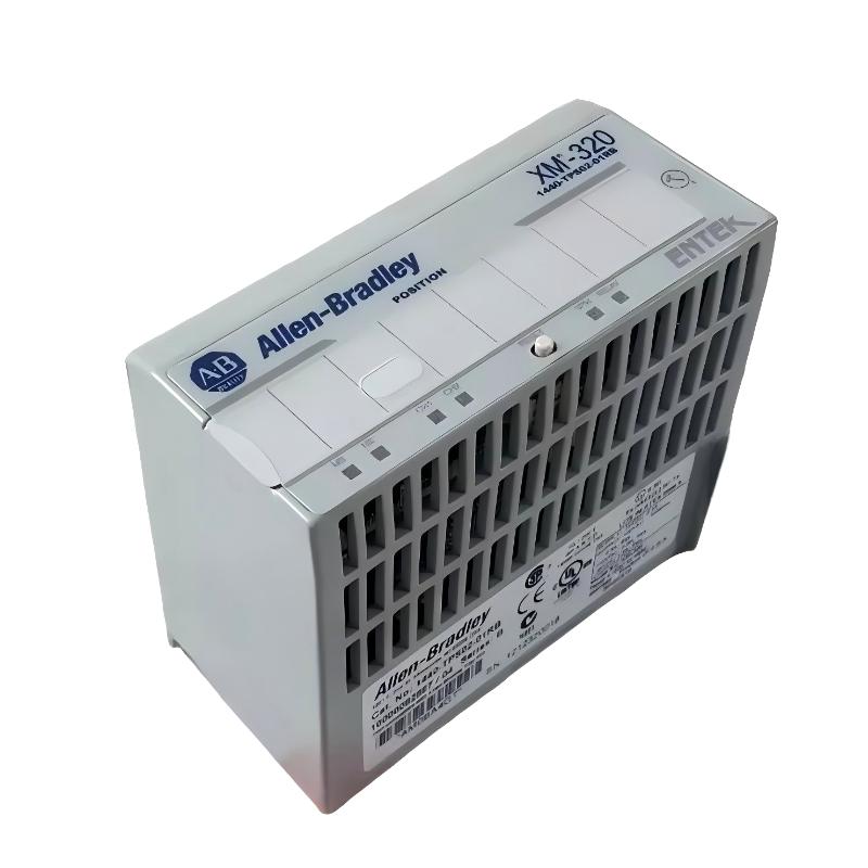
Table of Contents
- 1440-TPS02-01RB Position Measurement Module Installation Overview
- XM-320 Position Measurement Module Application
- Installation Preparation and Engineering Planning
- Module Mounting and Hardware Connection
- 1440-TPS02-01RB Sensor Wiring and Signal Setup
- PLC Controller System Configuration
- Setup and Commissioning Validation
- Field Installation Experience and Common Issues
- FAQs on 1440-TPS02-01RB Installation
- Engineering Summary
1440-TPS02-01RB Position Measurement Module Installation Overview
The Allen-Bradley 1440-TPS02-01RB Position Measurement Module Installation Guide explains the practical engineering process required for reliable XM-320 position monitoring applications. Correct installation includes mechanical mounting, sensor wiring, communication setup, and commissioning verification.
The Position Measurement Module is designed for industrial position monitoring where accurate displacement feedback is required. Typical applications include shaft position monitoring, expansion measurement, and critical equipment protection systems.
A successful installation depends on more than installing the Module. Engineers must verify the complete measurement path from the Sensor to the PLC Controller to ensure stable and accurate operation.
XM-320 Position Measurement Module Application
The Allen-Bradley 1440-TPS02-01RB plays an important role in industrial condition monitoring systems by collecting position-related signals and transferring measurement information to the control platform.
- Rotating equipment axial position monitoring
- Valve movement measurement
- Mechanical displacement monitoring
- Expansion monitoring applications
- Industrial protection systems
In one field project, engineers installed the module on a turbine monitoring system to establish a position reference during startup. The baseline data was later used for condition analysis and preventive maintenance.
Installation Preparation and Engineering Planning
Before starting the 1440-TPS02-01RB Setup process, engineers should prepare the following:
- Confirm application measurement requirements
- Verify sensor type and operating range
- Prepare correct wiring diagrams
- Check power supply quality
- Plan communication network arrangement
- Review System Configuration parameters
Good preparation reduces commissioning problems because most early failures are caused by incorrect wiring or incomplete configuration rather than hardware defects.
Module Mounting and Hardware Connection
The mechanical installation process should ensure stable connection between the module and the terminal base.
- Install the compatible terminal base inside the control cabinet
- Inspect connection points before inserting the module
- Install the 1440-TPS02-01RB Position Measurement Module correctly
- Confirm locking position and mechanical stability
- Check cabinet environment conditions
A secure installation prevents intermittent connection problems caused by vibration or cabinet movement.
1440-TPS02-01RB Sensor Wiring and Signal Setup
Sensor wiring is the most important part of the Installation Guide because position measurement accuracy depends on signal quality.
- Connect position sensors according to engineering drawings
- Verify input channel identification
- Check sensor polarity and signal direction
- Use appropriate shielding methods
- Separate measurement cables from high-power circuits
XM320_INSTALL_CHECK

MODEL = 1440-TPS02-01RB
CHECK = SENSOR_CONNECTION
CHECK = WIRING_POLARITY
CHECK = SIGNAL_QUALITY
CHECK = CHANNEL_MAPPING
During one commissioning activity, engineers found unstable position readings caused by signal cable routing close to a motor power line. After separating the cables, the measurement trend became stable.
PLC Controller System Configuration
After hardware installation, the System Configuration stage ensures that the Position Measurement Module processes signals correctly.
- Configure measurement channels
- Set engineering units
- Define alarm parameters
- Verify communication settings
- Save configuration information
Incorrect configuration may cause inaccurate readings even when the hardware installation is correct.
Setup and Commissioning Validation
A professional commissioning process includes:
- Power on the monitoring system
- Check module operating status
- Verify sensor signal response
- Compare displayed position values with actual reference
- Test alarm functions
- Record initial operating data
During one field commissioning case, engineers identified a 0.3 mm measurement deviation during initial testing. After calibration adjustment, the displayed position matched the mechanical reference value.
Field Installation Experience and Common Issues
Common installation problems found in real projects include:
- Incorrect sensor wiring
- Poor grounding practice
- Missing cable shielding
- Incorrect channel assignment
- Incomplete configuration backup
Experienced engineers normally perform signal validation before equipment operation because early detection of installation problems can significantly reduce startup delays.
FAQs on 1440-TPS02-01RB Installation
Why is sensor wiring important for the Position Measurement Module?
Because unstable or incorrect wiring can directly affect measurement accuracy and create abnormal position signals.
What should be completed before machine startup?
Engineers should verify wiring, power supply, communication, configuration parameters, and signal response before operation.
Can installation problems look like module faults?
Yes. Many troubleshooting cases initially appear to be hardware failures but are actually caused by wiring or configuration issues.
Engineering Summary
The Allen-Bradley 1440-TPS02-01RB Position Measurement Module requires careful installation practices including correct sensor wiring, stable mechanical mounting, accurate System Configuration, and complete commissioning verification. Field experience shows that professional setup procedures are essential for achieving reliable position monitoring performance in industrial applications.