

ProductPRODUCT
Featured products
Contact Us
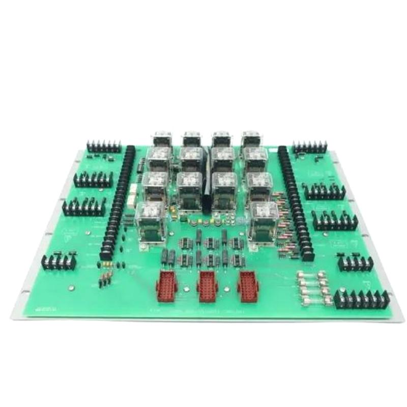
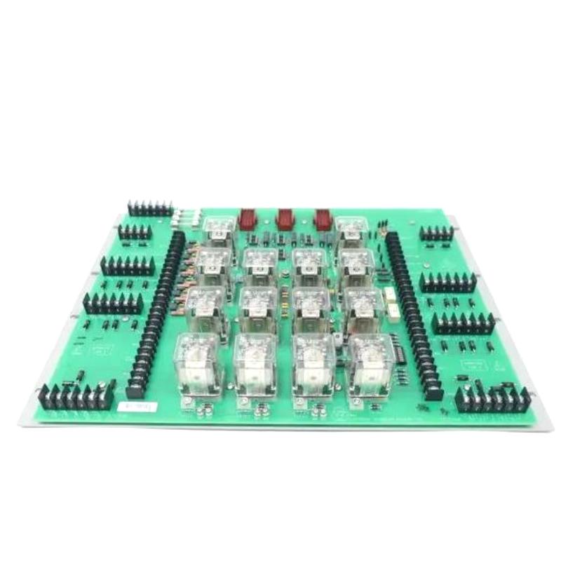
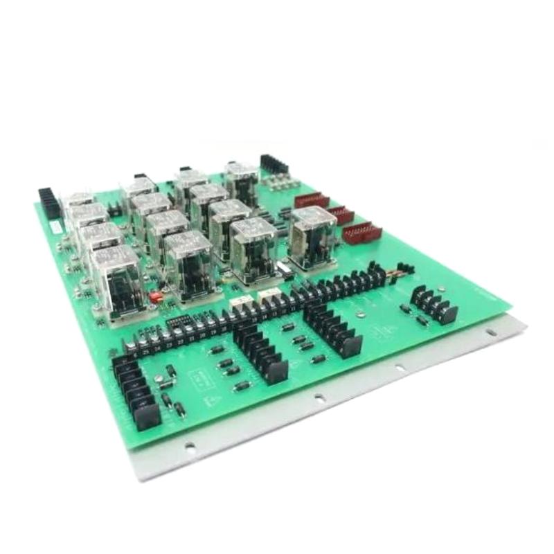
- ABB Bailey
- TPSTU02
- Turbine Protection System Termination Unit
- Sweden (SE)
- 120 × 100 × 50 mm
- 0.4 kg
- Xiamen, China
- New & In Stock
- T/T, PayPal, Western Union
- 1 Year
- 1-3 Working Days
- DHL, UPS, TNT, FedEx and EMS.
- 24-Hour Service
- COO
- 6
Our advantage

Global Logistics
We have a 10-year logistics and express cooperation agreement, so our products can be shipped to any place in the world.

Brand new and original
Our products are imported in bulk from the place of origin. Because of the cooperative relationship, our products are all original and 100% new.

24-hour service
We provide 7*24 hours service to our customers. We will be there whenever you need us.

Price advantage
All our products are priced very favorably because we have our own warehouse and supply.
| Company Information | |||
| [email protected] | |||
| Mobile | +8615980777398 | ||
| +8615980777398 | |||
| 15980777398 |
Product Overview
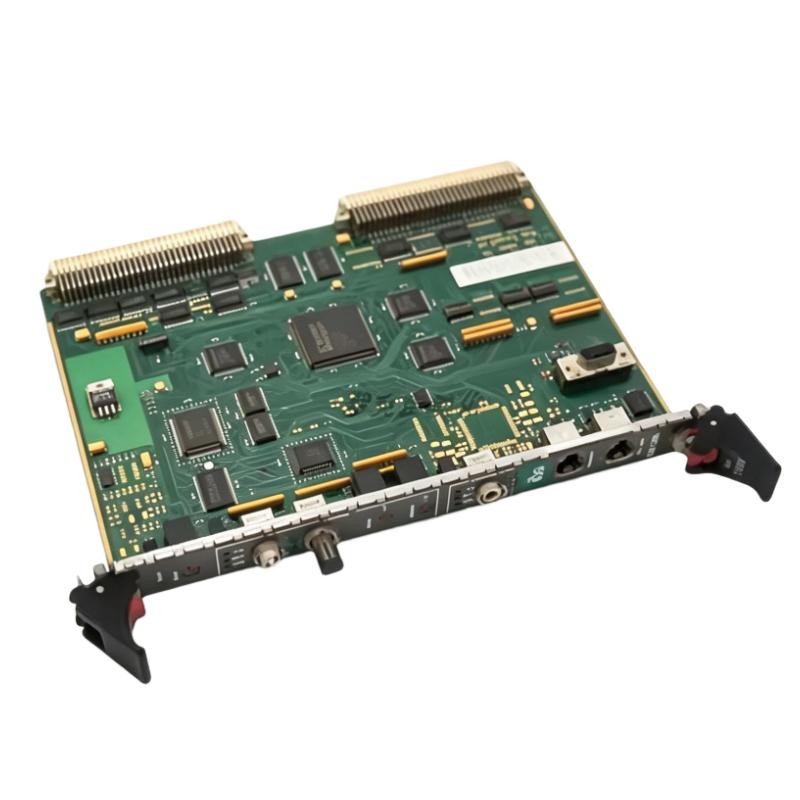
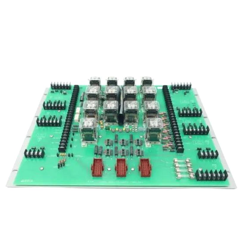
The ABB Bailey TPSTU02 Infi 90 Turbine Protection System Termination Unit is associated with the termination and field-wiring interface of a turbine protection system. In a turbine control installation, termination hardware connects external field circuits to the appropriate control-system interface, helping organize wiring between sensors, protection logic, and related equipment.
Turbine protection systems monitor operating conditions that may require an alarm, interlock, or protective shutdown. Signals from field devices must reach the control system through correctly wired and maintained connections. A termination unit serves as part of this signal interface, supporting the physical connection between field wiring and the associated system hardware.
The TPSTU02 is relevant when maintaining an existing ABB Bailey Infi 90 installation, replacing a damaged termination unit, or sourcing spare parts for a turbine protection cabinet. Before replacement, technicians should verify the complete part number, terminal arrangement, cabinet location, and compatibility with the installed protection-system configuration.
Technical Specifications
| Parameter | Specification |
|---|---|
| Brand | ABB Bailey |
| Model | TPSTU02 |
| Product Type | Turbine Protection System Termination Unit |
| Product Family | Infi 90 |
| System Application | Turbine Protection |
| Primary Function | Field-wiring termination and interface |
| Installation Environment | Industrial control cabinet |
| System Integration | Associated Infi 90 turbine protection hardware |
| Signal Interface | Depends on the installed system configuration |
| Terminal Arrangement | Verify against the unit’s wiring documentation |
| Mounting Requirements | Verify the original cabinet installation |
| Replacement Considerations | Part number, wiring, and system compatibility |
| Dimensions | 120 × 100 × 50 mm |
| Weight | 0.4 kg |
Product Features
- Turbine protection system application: Intended for use in the wiring and interface arrangement associated with turbine protection equipment.
- Field-wiring termination: Provides a connection point for the relevant field circuits within the configured protection system.
- Infi 90 system association: Relevant to maintenance and spare-parts requirements for installations using ABB Bailey Infi 90 equipment.
- Cabinet-level integration: Forms part of the physical wiring arrangement that connects field devices with control and protection hardware.
- Maintenance replacement: Can be considered when inspecting or replacing an existing unit, subject to verification of the original installation.
- Wiring organization: Helps keep field connections arranged at the appropriate termination point rather than requiring technicians to work directly with every connected device.
Working Principle
The TPSTU02 functions as a termination interface within the associated turbine protection installation. Its practical role is to establish the required electrical connection between designated field wiring and the corresponding protection-system circuits.
A typical signal path can be understood as follows:
Turbine Sensors or Field Devices → Field Wiring → TPSTU02 Termination Interface → Associated Protection-System Hardware → Protection Logic and Response
During normal operation, field devices monitor relevant turbine conditions and send electrical signals through the installed wiring. The termination interface connects those circuits to the appropriate system hardware, where the signals can be processed by the protection system.
When an abnormal condition occurs, the protection system evaluates the incoming information according to its configured logic. Depending on the application, the overall system may initiate an alarm, interlock, or shutdown command. The termination unit supports the wiring path; the protection logic and final response are handled by the associated system components.
The exact terminal assignments and signal types must be established from the documentation for the installed configuration. They should not be inferred from the TPSTU02 model designation alone.
Role in an Infi 90 Turbine Protection Architecture
| System Layer | Related Equipment or Function | Relationship to TPSTU02 |
|---|---|---|
| Field Instrumentation | Turbine sensors and switches | Supplies field signals through the installed wiring |
| Wiring Interface | TPSTU02 Termination Unit | Provides the designated termination point for associated circuits |
| Protection Hardware | Compatible Infi 90 interface and protection modules | Receives or handles signals through the configured wiring arrangement |
| Protection Logic | Configured turbine protection functions | Evaluates operating conditions and determines the required response |
| Output and Actuation | Alarms, interlocks, and shutdown-related equipment | Carries out the response commanded by the protection system |
| Operator Interface | Control-room monitoring equipment | Displays relevant operating status and alarms when supported by the system configuration |
Industrial Applications
| Application | How the Termination Unit Is Used |
|---|---|
| Steam Turbine Protection | Supports the field-wiring interface associated with turbine protection circuits |
| Power Generation Plants | Forms part of the wiring infrastructure in turbine protection cabinets |
| Industrial Turbomachinery | Supports connections between designated field circuits and the installed protection hardware |
| Existing ABB Bailey Infi 90 Installations | Serves as a maintenance or spare-parts item when the original configuration requires this model |
| Turbine Control Cabinet Maintenance | Provides a termination point that technicians can inspect during wiring and connection checks |
| Protection-System Refurbishment | May be retained or replaced as part of a planned cabinet maintenance project after compatibility verification |
Installation and Maintenance
- Confirm the full model number. Check that the replacement is ABB Bailey TPSTU02 and that the existing unit’s identification matches the maintenance documentation.
- Review the system drawings. Obtain the relevant cabinet layout, wiring diagram, and terminal assignments before disconnecting any circuits.
- Follow plant safety procedures. Apply the required isolation, lockout/tagout, and electrical safety measures before working on the protection cabinet.
- Record the original wiring. Label the conductors and document their terminal positions so that the connections can be restored accurately.
- Inspect the existing connections. Look for loose conductors, damaged insulation, corrosion, discoloration, or other signs of deterioration.
- Check the replacement part. Inspect the terminal area, housing, mounting features, and identification label before installation.
- Verify terminal assignments. Match each field circuit against the approved wiring diagram rather than relying solely on wire colors or the appearance of the old installation.
- Install using the specified method. Follow the cabinet’s mechanical arrangement and the manufacturer’s applicable installation instructions.
- Secure the wiring correctly. Ensure that conductors are properly seated and that terminals are tightened according to the applicable specifications.
- Check circuit continuity. Perform the approved continuity and wiring checks before restoring the equipment to service. Avoid tests that could damage connected electronics.
- Verify the complete protection path. After installation, carry out the required commissioning checks to confirm that signals reach the intended system hardware and that protection functions behave as specified.
- Update maintenance records. Record the replacement, inspection results, wiring changes, and any outstanding issues in the plant’s maintenance documentation.
Compatible System Components
| Component | Function in the System |
|---|---|
| ABB Bailey Infi 90 Protection Hardware | Provides the associated control or protection functions, subject to the installed configuration |
| Turbine Field Sensors | Monitor operating conditions and provide relevant measurement or status signals |
| Field Wiring and Instrument Cables | Carry electrical signals between field devices and the control cabinet |
| Terminal Blocks and Wiring Accessories | Organize and secure cabinet-level electrical connections |
| Protection Logic Modules | Process incoming signals and evaluate configured protection conditions |
| Alarm and Shutdown Interface Hardware | Supports the associated alarm, interlock, or shutdown response |
| Cabinet Grounding and Power Distribution Components | Support the electrical installation and its required grounding and supply arrangements |
Recommended Related Models
| Model or Product Group | Product Category | Relevance |
|---|---|---|
| ABB Bailey TPSTU02 | Turbine Protection System Termination Unit | The specified model for replacement or spare-parts sourcing |
| ABB Bailey Infi 90 Protection Modules | Protection and interface modules | Related system hardware to identify from the installed configuration |
| ABB Bailey Infi 90 Termination Units | Termination hardware | An appropriate product group to review when checking alternatives or related wiring interfaces |
| ABB Bailey Infi 90 System Interface Components | System interface hardware | Relevant when tracing the signal path between termination points and protection modules |
| ABB Bailey Infi 90 Power Components | Power-related hardware | May be relevant during broader cabinet maintenance, depending on the installed architecture |
For replacement procurement, prioritize the exact TPSTU02 model. Do not assume that another Infi 90 termination unit is interchangeable simply because it belongs to the same product family. Verify the terminal arrangement, electrical function, mounting method, and documented compatibility before selecting an alternative.
Key Advantages
- Clear wiring interface: Provides a designated termination point for the associated protection-system circuits.
- Support for existing installations: Relevant to maintaining turbine protection cabinets already using the specified hardware.
- Simplified troubleshooting: Allows technicians to inspect termination connections as part of a structured fault-finding process.
- Practical spare-parts use: Supports maintenance planning when the original equipment documentation identifies TPSTU02 as the required part.
- System-level integration: Works as part of the larger field-instrumentation and turbine-protection signal path.
Technical FAQs
What is the ABB Bailey TPSTU02 used for?
The TPSTU02 is identified as an Infi 90 Turbine Protection System Termination Unit. Its role is associated with the termination and interface of field wiring within the relevant turbine protection installation.
Is the TPSTU02 a standalone turbine protection controller?
No. It should be treated as a termination unit within a larger protection architecture. Protection decisions and shutdown logic depend on the associated protection hardware and the installed system configuration.
Can another ABB Bailey Infi 90 termination unit replace the TPSTU02?
Not automatically. Units within the same product family may have different terminal assignments, circuit functions, or installation requirements. Confirm interchangeability through the applicable hardware documentation before replacing the unit.
What should be checked before installing a replacement TPSTU02?
Confirm the full model number, terminal assignments, cabinet layout, wiring condition, and compatibility with the associated protection hardware. After installation, complete the required continuity, signal-path, and protection-system functional checks before returning the equipment to service.