
NewsNEWCENTER
Featured products
Contact Us
GE 8115-DO-DC Digital Output Module Fault Diagnosis
2026-11-17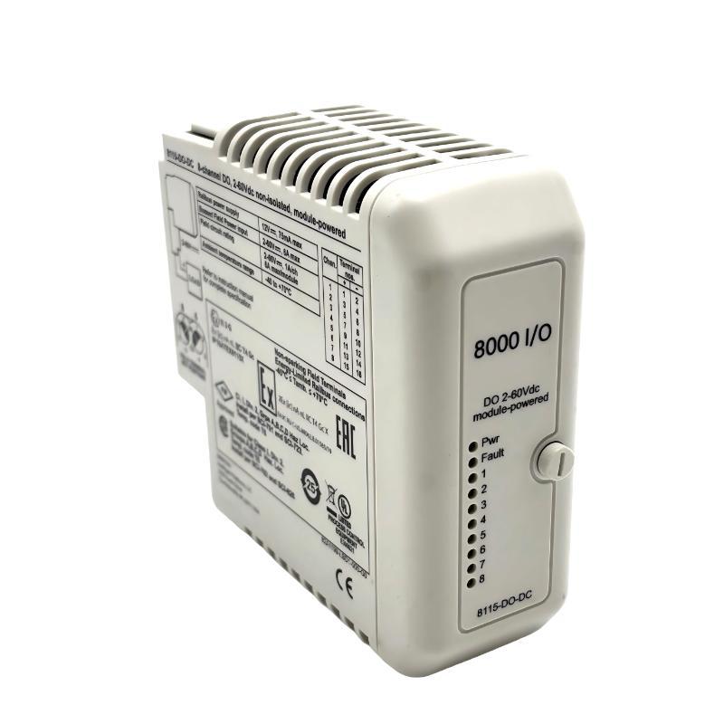
GE 8115-DO-DC digital output faults are commonly associated with field power interruptions, excessive load current, incorrect output wiring, and Railbus communication problems. When a PAC8000 control system issues an output command but the connected solenoid, relay, or actuator does not respond, the first task is to determine whether the failure originates in the controller, the output module, the field power supply, or the external load.
The GE 8115-DO-DC is an eight-channel, non-isolated, module-powered sourcing output module with a 2–60 VDC operating range. It uses solid-state switching technology and supports continuous, momentary, and pulsed output operation. Its maximum continuous current is 1 A per channel, with a total continuous module limit of 6 A. Understanding these electrical limitations is essential when performing Troubleshooting and Repair.
GE 8115-DO-DC Output Failure Symptoms in PAC8000 Systems
Output faults can appear in different ways depending on the connected field device and the operating condition of the control system.
- One output channel cannot activate its connected load.
- Several output channels stop operating simultaneously.
- A solenoid valve remains inactive despite an active controller command.
- An external relay operates intermittently.
- Field devices activate unexpectedly during startup.
- Output signals disappear when several loads operate together.
- Output voltage is lower than expected under load.
- The controller reports a module configuration or communication problem.
- A field device remains energized after a control sequence ends.
These symptoms do not necessarily indicate an internal electronic failure. A failed field power supply, damaged load, incorrect output assignment, or common wiring problem can create similar conditions.
GE 8115-DO-DC Troubleshooting Logic: Identify the Failure Boundary
Experienced maintenance engineers generally avoid replacing an output module before determining where the electrical command is lost. The GE 8115-DO-DC troubleshooting process can be divided into four diagnostic boundaries.
Controller Command Boundary
Confirm that the controller actually generates the intended output command. Check the program logic, permissive conditions, interlocks, and output address.
If the controller never issues the command, replacing the digital output module will not resolve the problem.
Railbus Communication Boundary
Verify that the PAC8000 controller can communicate with the installed I/O module through the Railbus. A module recognition or communication problem can prevent output commands from reaching the switching circuitry.
Electrical Switching Boundary
Measure the field power supply and the relevant output terminal. Determine whether the module receives the command and whether the switching circuit produces the expected voltage.
Field Load Boundary
If the correct electrical output is present, inspect the external device. Open solenoid coils, damaged relay coils, broken conductors, and mechanical actuator problems can all prevent the expected operation.
GE 8115-DO-DC Output Channel Not Switching: Root Cause Investigation
A single inactive channel is often easier to diagnose than a complete module failure. The investigation should begin with a comparison between the faulty channel and a known working channel.
Incorrect Channel Assignment
One frequent commissioning problem is a mismatch between the controller output address and the physical terminal channel.
For example, the control program may activate output channel 4 while the field device is physically connected to channel 5. The controller appears to operate normally, but the intended device does not respond.
Check the hardware configuration, channel mapping, field terminal identification, and application logic together.
Open Field Circuit
If the output switches correctly but the load remains inactive, inspect the complete field circuit.
- Check conductor continuity.
- Inspect terminal tightening and contact condition.
- Measure the load coil resistance.
- Verify the positive supply and return path.
- Inspect intermediate disconnects and fuses.
A disconnected conductor can create an apparent module fault even when the solid-state output is functioning normally.
Excessive Load Current
The 8115-DO-DC supports 1 A continuous switching current per channel, but the total continuous current for the module is limited to 6 A.
Operating multiple inductive loads simultaneously can increase the demand on the shared field power supply. Engineers should calculate the actual load current instead of assuming that every channel can continuously operate at its individual maximum rating.
GE 8115-DO-DC Field Power Problems and Voltage Drop Analysis
The module requires 2–60 VDC bussed field power. If this supply is missing, unstable, or insufficient for the connected loads, the output system may become unreliable.
Low Field Supply Voltage
A supply voltage that appears normal without a load may fall significantly when several output channels become active.
For example, an engineer may measure 24 VDC at the power supply while all outputs are inactive. When multiple solenoid valves are energized, the voltage at the field terminal may decrease because of an undersized supply, poor connections, or excessive cable resistance.
Measurements should therefore be taken both under idle conditions and during representative operating loads.
Shared Power Distribution Problems
The bussed field power arrangement should be examined carefully when multiple channels fail together.
Possible causes include:
- Power supply overload.
- Loose field power connections.
- Damaged distribution conductors.
- Incorrect supply polarity.
- Blown field protection devices.
- Excessive voltage drop across terminal connections.
When several channels show similar symptoms at the same time, investigate the shared power path before treating the problem as multiple independent output failures.
GE 8115-DO-DC Solid-State Output Leakage and Unexpected Activation
Unlike mechanical relay contacts, solid-state outputs can exhibit a small OFF-state leakage current. The specified maximum OFF leakage current of the GE 8115-DO-DC is 1.0 mA.
This characteristic is important when troubleshooting sensitive loads that may respond to very small currents.
Why Does a Field Device Remain Slightly Energized?
A high-impedance electronic input, indicator circuit, or sensitive relay may respond to residual leakage current even when the output is commanded OFF.
Before concluding that the output transistor is damaged, check whether the observed voltage is caused by the normal OFF-state characteristics of the module.
Practical Diagnostic Approach
- Confirm that the controller output command is OFF.
- Measure the output voltage with the load connected.
- Compare the measurement with the expected load behavior.
- Disconnect the load using an approved isolation procedure.
- Evaluate whether the remaining voltage is consistent with OFF-state leakage.
- Check the connected device’s minimum operating current and voltage.
Do not apply an arbitrary resistor or short circuit to eliminate residual voltage. Any additional load or suppression component must be selected according to the electrical specifications and application requirements.
GE 8115-DO-DC Railbus Communication and Module Recognition Faults
A digital output module can have healthy field wiring and still fail to operate if its controller communication path is interrupted.
Railbus-related faults should be investigated when multiple output channels become unavailable, the module is not correctly recognized, or the problem appears immediately after carrier maintenance.
Common Railbus-Related Causes
- Incorrect module position in the hardware configuration.
- Poor contact between the module and carrier.
- Damaged carrier connections.
- Incorrect module identification or configuration.
- Controller startup or initialization problems.
- Unstable internal system power.
Module Recognition Verification
Use the available PAC8000 engineering and diagnostic tools to verify the module identity, hardware position, and communication status.
Compare the software configuration with the physical module installation. If the module has been replaced, confirm that the configured module type matches the installed 8115-DO-DC.
GE 8115-DO-DC Output Current Overload and Thermal Stress Diagnosis
Overload conditions deserve particular attention because the output channels may be connected to inductive devices that draw higher current during initial energization.
The specified switching current limits are:
| Operating Condition | Maximum Current per Channel |
|---|---|
| Continuous operation | 1 A |
| Pulse shorter than 100 ms | 4 A |
| Pulse shorter than 20 ms | 6 A |
The module is also subject to aggregate switching limits. The total continuous load is limited to 6 A per module. The specified aggregate instantaneous limits are 10 A for periods shorter than 100 ms and 18 A for periods shorter than 20 ms.
These short-duration limits are not permission to operate the module continuously at elevated current.
Inductive Load Considerations
Solenoid valves and relay coils produce inductive voltage transients when switched. Incorrect suppression arrangements or unsuitable load characteristics can increase electrical stress on the output circuitry.
Check whether the field device requires a suitable suppression component and ensure that its selection is compatible with the output module and switching requirements.
GE 8115-DO-DC Fault Diagnosis Using Electrical Measurements
Electrical measurements provide a more reliable diagnostic basis than visual inspection alone. The following examples illustrate a practical measurement sequence for a 24 VDC field circuit.
Output Voltage Diagnostic Sequence
Module: GE 8115-DO-DC
Channel: DO3
Field supply: 24 VDC

Diagnostic checks:

A. Measure bussed field power.
B. Verify controller output command.
C. Measure output terminal voltage.
D. Check the load current.
E. Inspect the field return connection.

Interpretation:

No field supply:
    Investigate the external DC supply.

Supply present, no output command:
    Check controller logic and interlocks.

Command present, output voltage absent:
    Investigate module switching and carrier connections.

Output voltage present, load inactive:
    Inspect load wiring and field device.

Output voltage unstable under load:
    Investigate power capacity and circuit resistance.
Understanding the ON-State Voltage Drop
The specified maximum ON-state voltage drop is 0.25 V. This parameter helps engineers evaluate the switching circuit under an appropriate load condition.
For example, if the field supply measures 24 VDC and the output is operating normally, the voltage available to the load should reflect the supply voltage minus the switching-path voltage drop and other wiring losses.
A substantially different result should trigger further investigation into the supply, connections, load, and output circuit.
GE 8115-DO-DC Repair Strategy: Component Inspection and Replacement Decisions
Repair decisions should be based on confirmed electrical faults rather than assumptions. A failed output channel may result from external overload, wiring damage, or an internal solid-state switching problem.
Inspection of the Module
After following the approved isolation and removal procedure, inspect the module for:
- Discoloration around electronic components.
- Burn marks or unusual odor.
- Damaged PCB tracks.
- Corrosion or contamination.
- Damaged carrier contacts.
- Evidence of overheating.
Repair Versus Replacement
Component-level repair should only be considered by qualified industrial electronics technicians with appropriate diagnostic equipment and technical documentation.
Solid-state output circuits may contain semiconductor devices that cannot be reliably assessed through visual inspection. A board that appears physically normal may still contain a damaged switching component.
Where an internal fault has been established, replacement with a compatible module is often preferable to an undocumented repair, particularly in continuously operating process installations.
GE 8115-DO-DC Realistic Field Troubleshooting Scenario
Illustrative engineering case: Multiple solenoid valves become unstable during simultaneous operation.
A PAC8000 control system uses the GE 8115-DO-DC to operate several DC solenoid valves. During normal production, the valves operate correctly when activated individually. However, when several outputs are commanded simultaneously, some valves respond intermittently.
Initial Observations
- Controller output commands appear normal.
- Individual valves operate correctly during isolated testing.
- Multiple simultaneous output commands produce unstable operation.
- The problem is more noticeable during high-load sequences.
Engineering Investigation
The technician first checks the module configuration and confirms that the controller is issuing the expected commands.
Next, the field supply is measured under different operating conditions. The voltage is stable when the outputs are inactive but decreases when several loads are energized.
The engineer then calculates the combined load current and checks the power supply capacity, field distribution conductors, and terminal connections.
Identified Cause and Corrective Action
In this illustrative case, the problem is traced to inadequate field power distribution rather than an internal output module failure. The combined load demand and voltage drop exceed the available margin of the existing supply arrangement.
The corrective work involves reviewing the DC power supply capacity, improving the field distribution connections, and ensuring that the connected loads remain within the module’s electrical limits.
Post-Repair Validation
After corrective work, the engineer repeats the simultaneous output test and measures the field voltage under representative operating conditions.
Each output is checked individually and as part of the combined operating sequence. Stable field voltage and correct actuator operation confirm that the fault has been addressed.
The important lesson is that multiple simultaneous output failures should prompt an investigation of shared electrical resources before the module is replaced.
GE 8115-DO-DC Troubleshooting Reference and Fault Comparison
| Fault Symptom | Likely Cause | Diagnostic Action |
|---|---|---|
| One channel does not switch | Incorrect assignment or channel circuit fault | Verify controller mapping and terminal voltage |
| All channels unavailable | Field power or Railbus problem | Check common supply and module recognition |
| Output voltage too low | Supply voltage drop or poor connection | Measure voltage under load |
| Load remains slightly energized | Normal OFF-state leakage or circuit interaction | Evaluate leakage current and load characteristics |
| Intermittent valve operation | Overload or unstable field supply | Calculate combined load current |
| Output remains active unexpectedly | Controller logic or output initialization setting | Check output command and fail-safe configuration |
| Fault after module replacement | Incorrect configuration or carrier seating | Verify module identity and installation position |
| Repeated output circuit damage | Unsuitable inductive load or electrical transients | Inspect load and suppression arrangement |
GE 8115-DO-DC Maintenance and Long-Term Reliability
Preventive maintenance can reduce unexpected output failures in PAC8000 installations. The maintenance strategy should focus on field power stability, load condition, electrical connections, and controller diagnostics.
Recommended Maintenance Activities
- Inspect field terminal connections during scheduled shutdowns.
- Check DC supply voltage under representative load conditions.
- Review output channel assignments after system modifications.
- Monitor the combined continuous current demand.
- Inspect solenoid and relay coils for abnormal electrical characteristics.
- Check carrier contacts for contamination or mechanical damage.
- Review output initialization and fail-safe configuration.
- Record recurring channel failures and operating conditions.
For installations in hazardous areas, maintenance and replacement work must follow the applicable area classification, equipment certification, and isolation procedures.
GE 8115-DO-DC Troubleshooting Technical FAQs
Why does the GE 8115-DO-DC have no output voltage?
Possible causes include missing bussed field power, an inactive controller command, incorrect hardware configuration, poor carrier contact, or an internal output circuit fault. Check these conditions systematically.
Why does only one output channel fail?
A single-channel failure may result from incorrect wiring, an open load circuit, a damaged terminal connection, or an internal switching component problem. Compare the faulty channel with a working channel under equivalent conditions.
Can excessive current damage the 8115-DO-DC?
Yes. Operating outside the specified channel and aggregate current limits can cause excessive electrical and thermal stress. The continuous module limit is 6 A, even though individual channels support up to 1 A continuous.
What causes a solenoid valve to operate intermittently?
Common causes include unstable field power, excessive combined load demand, loose wiring, poor return connections, and unsuitable suppression arrangements.
Does the 8115-DO-DC have isolated output channels?
No. It is a non-isolated output module with a shared bussed field power arrangement. This must be considered when designing field circuits.
What is the maximum OFF-state leakage current?
The specified maximum OFF-state leakage current is 1.0 mA. Sensitive external loads should be evaluated to ensure that this characteristic does not cause unwanted activation.
How can I distinguish a Railbus problem from an output circuit fault?
Check the controller’s module recognition and communication diagnostics first. If communication is normal, investigate field power, individual output commands, terminal voltage, and connected loads.
Can the module control pulsed outputs?
Yes. It supports discrete and pulsed output modes, with a specified pulse width range of 2 ms to 130 s, subject to system configuration and application support.
What should I check when several output channels fail simultaneously?
Investigate shared field power, common return connections, carrier contacts, and Railbus communication before assuming that multiple independent output circuits have failed.
When should the GE 8115-DO-DC be replaced?
Replacement should be considered when an internal switching fault has been confirmed, the module has physical or electrical damage, or its operation remains abnormal after external wiring, power, configuration, and load problems have been eliminated.
GE 8115-DO-DC Troubleshooting Conclusion and Overall Technical Assessment
The GE 8115-DO-DC is an eight-channel solid-state digital output module designed for DC field control in GE PAC8000 distributed I/O systems. Its sourcing output architecture, 2–60 VDC operating range, and support for discrete and pulsed switching make it suitable for a wide range of industrial control applications.
When troubleshooting this module, engineers should pay particular attention to field power distribution, channel current limits, Railbus communication, OFF-state leakage, and the electrical characteristics of connected inductive loads.
The most effective Fault Diagnosis approach is to follow the complete signal path from controller command to physical field device. Measuring voltage under load, calculating aggregate current, and comparing faulty channels with working channels can help identify the actual failure point without unnecessary component replacement.
Ultimately, reliable GE 8115-DO-DC operation depends on correct System Configuration, appropriate field wiring, stable DC power, and periodic electrical inspection. A disciplined Troubleshooting and Repair process helps maintain PAC8000 system availability and reduces recurring digital output failures in industrial automation environments.