
NewsNEWCENTER
Featured products

Contact Us
GE 8115-DO-DC Digital Output Module Installation Guide
2026-11-17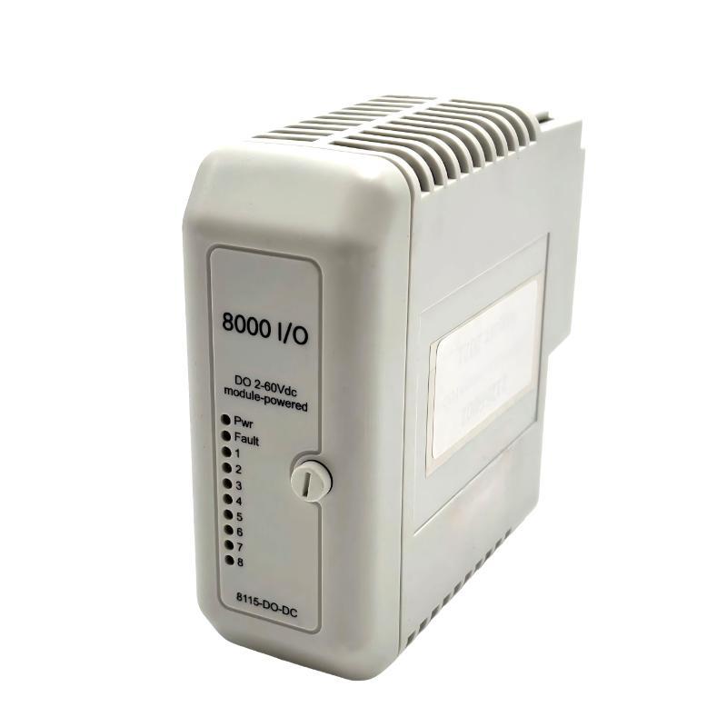
The GE 8115-DO-DC installation requires correct field power distribution, output load selection, and Railbus communication verification. This PAC8000 8-channel digital output module is designed to switch DC-powered field devices such as solenoid valves, interposing relays, and industrial actuators. It supports an output voltage range of 2–60 VDC and provides eight sourcing output channels with a maximum continuous switching current of 1 A per channel, subject to the overall module current limitation.
Unlike a conventional relay output card, the GE 8115-DO-DC uses solid-state switching technology. Its outputs are non-isolated and module-powered, meaning that field power distribution and load wiring must be considered together during installation. A correct Installation Guide should therefore address both the physical mounting arrangement and the electrical relationship between the Railbus, bussed field power, and individual output loads.
GE 8115-DO-DC PAC8000 Module Architecture and Operating Principle
The 8115-DO-DC belongs to the GE PAC8000 distributed I/O family. It receives output commands through the Railbus and switches the corresponding DC field circuits.
The module provides eight sourcing output channels. When a channel is activated by the controller, its solid-state switching circuit supplies the connected load from the shared bussed field power arrangement.
GE 8115-DO-DC Digital Output Characteristics
- Number of output channels: 8.
- Output type: DC discrete sourcing.
- Output voltage range: 2–60 VDC.
- Isolation: Non-isolated.
- Output technology: Solid-state switching.
- Continuous switched current: 1 A per channel, subject to module limits.
- ON-state voltage drop: 0.25 V maximum.
- OFF-state leakage current: 1.0 mA maximum.
- Maximum Railbus response time: 1 ms.
- Pulse width range: 2 ms to 130 s.
Understanding the Shared Field Power Arrangement
The GE 8115-DO-DC requires a 2–60 VDC bussed field power supply. This supply provides the energy used by the output channels to operate external loads.
Because the outputs are non-isolated and share a common field power arrangement, engineers must verify the power supply rating, conductor sizing, common connections, and combined load demand before commissioning.
GE 8115-DO-DC Installation Preparation and Compatibility Checks
Before installing the module, inspect the PAC8000 I/O carrier and confirm that the available field terminal assembly is compatible with the application. The module uses a B6 key code and has a nominal width of 42 mm.
Required Installation Checks
- Confirm the complete part number is 8115-DO-DC.
- Verify the PAC8000 carrier and Railbus arrangement.
- Confirm that the carrier supports the B6 module key code.
- Check the available 2–60 VDC field power supply.
- Calculate the combined current of all connected loads.
- Verify the field terminal type and fuse arrangement.
- Inspect the module contacts and carrier connectors.
- Review the controller configuration and output assignments.
Compatible Field Terminal Selection
The terminal assembly should be selected according to the field wiring environment and applicable installation requirements.
| Application | Field Terminal | Configuration |
|---|---|---|
| General-purpose field wiring | 8604-FT-FU | Fused terminal |
| General-purpose field wiring | 8602-FT-ST | Standard terminal |
| Class I, Division 2 or Zone 2 | 8611-FT-FU | Non-arcing fused terminal |
| Class I, Division 2 or Zone 2 | 8610-FT-NA | Non-arcing terminal |
Where the selected terminal assembly does not provide suitable field protection, additional field wiring fusing should be evaluated according to the applicable electrical and hazardous-area requirements.
GE 8115-DO-DC Field Wiring and DC Power Distribution
Field wiring is one of the most important parts of the GE 8115-DO-DC Installation Guide. Incorrect polarity, insufficient power capacity, or unsuitable load selection can cause output malfunction even when the module itself is operating correctly.
DC Supply Connection
Connect the external field supply to the designated bussed field power terminals according to the PAC8000 carrier and terminal assembly wiring diagram.
The supply must remain within the specified 2–60 VDC range. Its available current must also be sufficient for the combined load demand under the intended operating conditions.
Individual Output Channel Wiring
Each output channel should be connected to its corresponding field device. Typical applications include:
- DC solenoid valves.
- Interposing relay coils.
- Industrial annunciators.
- DC contactor control circuits.
- Process equipment enable signals.
- Discrete actuator commands.
For sourcing outputs, the module switches the positive side of the field supply to the load. The load return must be connected to the appropriate field power return according to the terminal wiring diagram.
Do not assume that the wiring arrangement is identical to a sinking output module. The 8115-DO-DC is a sourcing output device, and its field circuit must be designed accordingly.
Load Current Calculation
Although the module supports 1 A continuous switching current per channel, the total continuous load current is limited to 6 A per module. Therefore, eight channels should not automatically be loaded at 1 A simultaneously.
For example, if six output channels each operate a 0.8 A solenoid, the combined continuous demand is:
6 × 0.8 A = 4.8 A
This is within the 6 A continuous module limit, assuming the individual channel and field power requirements are also satisfied.
When selecting loads, engineers should also consider startup current, inductive characteristics, operating frequency, and the possibility of simultaneous switching.
GE 8115-DO-DC Output Configuration and Pulse Setup
The 8115-DO-DC supports discrete output operation, momentary pulses, and continuous pulse configurations where supported by the controller and system software.
Output Initialization State
The output initialization state is defined by a predefined value. During System Configuration, engineers should verify that the selected initialization behavior is appropriate for the connected equipment.
For example, a valve control output may need to remain inactive during controller startup until all process permissives have been established.
Fail-Safe Output Behavior
The module supports predefined-value and last-value fail-safe arrangements. The correct choice depends on the process application and the risk associated with losing controller communication.
A motor enable signal, valve command, or alarm output may require different failure behavior. Engineers should therefore document the intended response before commissioning rather than applying one fail-safe strategy to every channel.
Pulse Width Configuration
The supported pulse width range is 2 ms to 130 s. This allows the module to support applications requiring timed switching rather than continuously maintained output states.
Pulse settings should be verified against the response requirements of the field device. A short pulse may be appropriate for a counting or triggering application, while a solenoid valve may require a longer activation period.
GE 8115-DO-DC PAC8000 Setup and Commissioning Procedure
Commissioning should verify the complete control path, beginning with the controller command and ending with the physical response of the connected load.
Controller and Railbus Verification
Confirm that the PAC8000 controller recognizes the installed module and that the configured hardware position corresponds to the physical installation.
Check the module identity, carrier position, channel assignments, and relevant controller diagnostics. A hardware configuration mismatch should be corrected before testing field outputs.
Output Channel Functional Testing
- Keep the controlled process in a safe maintenance condition.
- Verify the field supply voltage.
- Confirm the channel assignment in the controller configuration.
- Issue an approved test command to one output.
- Measure the voltage at the corresponding field terminal.
- Observe the connected device response.
- Return the channel to its intended operating state.
- Repeat the test for the remaining channels.
Testing one output at a time makes it easier to identify crossed wiring, incorrect channel assignments, and load-specific problems.
Output Response Verification
The maximum response time from a Railbus command to an output change is specified as 1 ms. Actual field device response will also depend on load characteristics, wiring, controller execution, and the mechanical behavior of the connected equipment.
Do not confuse the electronic switching response with the operating time of a solenoid, relay, or actuator.
GE 8115-DO-DC Installation Example: Solenoid Valve Control
Illustrative engineering commissioning scenario: A PAC8000 system is configured to operate six DC solenoid valves through the GE 8115-DO-DC digital output module.
Each valve has a nominal operating current of 0.8 A at the selected field supply voltage. The combined continuous load is 4.8 A, which remains below the module’s 6 A continuous total limit.
During commissioning, the engineer notices that one valve does not operate when its controller output is activated.
Instead of replacing the module, the following checks are performed:
- The controller output assignment is confirmed.
- The Railbus module configuration is checked.
- The field supply is measured at the terminal assembly.
- The output voltage is measured during activation.
- The valve coil resistance and wiring continuity are inspected.
The investigation identifies an open conductor in the individual valve circuit. After correcting the wiring, the output switches the load correctly.
This scenario illustrates why output commissioning should include both electrical measurements and actual field device verification.
GE 8115-DO-DC Installation Technical FAQs
What is the GE 8115-DO-DC used for?
It is an eight-channel PAC8000 DC digital output module used to control field devices such as solenoids, relays, and industrial actuators.
What is the output voltage range of the 8115-DO-DC?
The specified output voltage range is 2–60 VDC, supplied through the bussed field power arrangement.
Is the GE 8115-DO-DC a sourcing or sinking module?
It is a sourcing digital output module. The output switches the positive side of the field supply to the connected load.
How many output channels does the module provide?
It provides eight independent DC discrete output channels.
What is the maximum continuous current per channel?
The maximum continuous switched current is 1 A per channel, with an overall continuous module limit of 6 A.
Can the 8115-DO-DC operate solenoid valves?
Yes. It is designed for applications including solenoid and relay control, provided that the load voltage, current, and switching characteristics remain within the specified limits.
What is the maximum pulse width?
The configurable pulse width range is 2 ms to 130 s, subject to controller configuration and application support.
Does the module require an external field power supply?
Yes. It requires a 2–60 VDC bussed field power supply to operate its output loads.
What is the maximum output response time?
The specified maximum response time from a Railbus command to an output change is 1 ms.
Which field terminals are compatible with the module?
Compatible options include 8604-FT-FU, 8602-FT-ST, 8611-FT-FU, and 8610-FT-NA, selected according to the wiring environment and applicable installation requirements.
What should be checked if an output does not operate during commissioning?
Check controller configuration, Railbus communication, field power, output voltage, terminal wiring, load resistance, and the connected device condition.
GE 8115-DO-DC Installation Conclusion and Overall Technical Assessment
The GE 8115-DO-DC is a practical eight-channel digital output solution for PAC8000 distributed control applications. Its 2–60 VDC sourcing outputs, solid-state switching design, and support for discrete and pulsed operation make it suitable for controlling a range of industrial DC field devices.
Successful installation depends on correct carrier compatibility, field power distribution, load current calculations, terminal selection, and controller System Configuration. Particular attention should be given to the 6 A continuous total module limit rather than considering only the individual 1 A channel rating.
A structured Installation Guide and commissioning process helps ensure that every output channel responds correctly, that the connected loads remain within electrical limits, and that the module operates reliably within the PAC8000 control architecture.