
NewsNEWCENTER
Featured products



Contact Us
GE 531X307LTBAJG1 LAN I/O Terminal Board Troubleshooting Guide
2026-11-17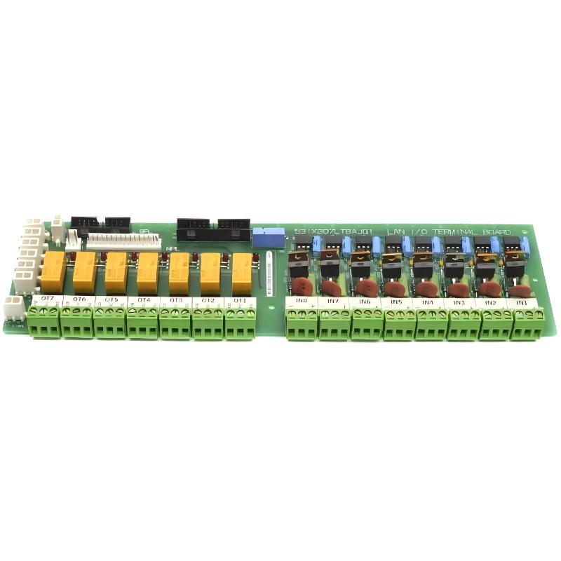
GE 531X307LTBAJG1 LAN I/O Terminal Board faults are not always caused by a defective circuit board. Missing input signals, incorrect G1/G2 hardware identification, loose field terminals, ribbon cable problems, and external relay circuit failures can produce similar symptoms in a GE drive or exciter system. Effective Fault Diagnosis therefore begins with identifying where the expected signal disappears rather than replacing the board based on an alarm alone.
The GE 531X307LTBAJG1 provides eight configurable input connections and seven low-voltage, low-current Form C relay outputs. It also interfaces with the drive control board and associated terminal boards. When an input or output behaves incorrectly, technicians should examine the complete signal path, including external devices, terminal connections, internal interfaces, and control logic.
GE 531X307LTBAJG1 Fault Symptoms Observed in Drive Systems
Several operating problems can indicate an issue involving the LAN Terminal Board or its connected circuits.
- Drive enable signals are not recognized.
- External interlocks appear permanently active or inactive.
- Input LEDs do not respond to applied field signals.
- Relay outputs fail to change contact state.
- Drive status indications do not match external switch positions.
- Control signals become intermittent during machine operation.
- Signals disappear after cabinet maintenance or board replacement.
- Communication or signal distribution problems occur between associated control boards.
These symptoms are diagnostic clues, not proof of board failure. An engineer should first establish whether the fault is located in the field wiring, the input circuit, the relay section, or the host control system.
GE 531X307LTBAJG1 Fault Diagnosis: Follow the Signal Before Replacing Hardware
A useful troubleshooting method is to divide the system into three functional areas.
Field Signal Level
This section includes external switches, interlocks, contactors, field power supplies, and incoming conductors. A signal that is missing at its source cannot be corrected by replacing the LAN Terminal Board.
Terminal Board Level
The second area includes input terminal circuits, input indicators, relay drivers, contact connections, and plug-in connectors. Here, technicians should verify whether the board receives the expected electrical condition and produces the appropriate output response.
Drive Control Level
The final area includes the associated drive control board, NTB/3TB terminal board, and application control logic. A correctly detected input may still fail to produce the expected machine response if another permissive or interlock condition is not satisfied.
This division prevents a common maintenance mistake: confusing a control logic problem with an electrical terminal board fault.
GE 531X307LTBAJG1 Input Signal Faults and Electrical Causes
Input-related problems are among the first conditions to investigate when an external command or interlock is not recognized.
Missing Input Voltage
If an external device is expected to activate IN1–IN8, measure the actual voltage at the corresponding terminal. Do not rely exclusively on the indicator light or the status displayed by the drive controller.
Possible causes include:
- Failed external power supply.
- Open field wiring.
- Loose terminal connections.
- Incorrect input voltage selection.
- Damaged external switch contacts.
Input LED Does Not Respond
LED1–LED8 are associated with the input source conditions. If a compatible signal is present at the input but the expected indicator remains off, investigate the terminal connection and input circuit.
Check the actual voltage at the board, verify polarity where applicable, and compare the measurement with the input specifications. If the signal is present and stable but the indicator does not respond, further board-level inspection may be necessary.
Intermittent Input Signals
Intermittent operation can result from loose conductors, vibration-related connector movement, poor contact resistance, or electrical interference.
Where an input changes state unexpectedly, inspect the wiring route and terminal condition. Pay particular attention to long cable runs near motor conductors, switching equipment, and other high-noise circuits.
GE 531X307LTBAJG1 Input Leakage and False Signal Diagnosis
Not every input that remains active is receiving a valid command from the external control device. Leakage current can create unexpected input behavior, particularly in circuits containing electronic switches, indicators, or devices connected in series.
The GE 531X307LTBAJG1 input circuits have switching thresholds associated with approximately 6 V and 0.5 mA peak AC/DC conditions, as specified for the applicable input configuration. Actual field behavior must be assessed using the correct circuit documentation.
Typical Leakage Current Investigation
Consider an external interlock that should remain inactive when its switch is open. If the input LED remains illuminated, the technician should not immediately conclude that the input circuit is damaged.
Instead, investigate:
- Whether the external switch is actually open.
- Whether another device is connected in series with the input.
- Whether leakage current is present through an electronic output.
- Whether induced voltage is affecting the signal conductor.
- Whether the input wiring has been connected to the correct terminal.
Where leakage is suspected, use an appropriate measurement method to assess the circuit under operating conditions. Do not apply an arbitrary resistor or short-circuit the input to suppress an unwanted signal.
GE 531X307LTBAJG1 Relay Output Faults and Contact Diagnosis
The output section contains seven Form C relay contact connections, identified as OT1–OT7. Each output provides a three-terminal contact arrangement.
Relay-related faults can be divided into three categories: the relay is not commanded, the relay is commanded but does not operate, or the relay operates but the external load does not respond.
Relay Indicator Does Not Activate
LED17–LED23 are associated with the energized conditions of relays RX1–RX7. If an expected relay indicator remains off, investigate the control command and associated drive logic before examining the contact circuit.
Potential causes include:
- Missing relay control command.
- Incorrect input or interlock condition.
- Internal signal distribution problem.
- Damaged relay drive circuitry.
- Loose internal connection.
Relay Indicator Activates but the Output Does Not Switch
If the corresponding relay indicator is illuminated but the external device does not respond, measure the contact condition using an appropriate isolated test procedure.
Possible causes include worn relay contacts, incorrect terminal identification, damaged external wiring, an open load circuit, or an unsuitable external supply.
Remember that an energized relay indicator does not independently prove that the external contact circuit is healthy.
GE 531X307LTBAJG1 Communication and Ribbon Cable Troubleshooting
The GE 531X307LTBAJG1 is part of a larger drive control interface arrangement. Problems involving its internal connections may affect signal distribution even when the field input circuits appear normal.
The G1 version includes the 8PL connection and CI1PL–CI8PL input plugs. These connectors should be checked carefully during troubleshooting, particularly after board replacement or cabinet maintenance.
Ribbon Cable Inspection
- Check for partially inserted connectors.
- Inspect pins for mechanical damage.
- Confirm connector orientation.
- Look for damaged insulation or crushed cable sections.
- Check for routing alongside high-current power cables.
Where the system uses a 26-conductor ribbon cable, its documented maximum interconnection length and installation requirements should be observed. A cable that has been extended or rerouted without engineering review may introduce signal integrity problems.
G1 and G2 Revision Mismatch
One important replacement-related fault is installing a G2 terminal board in an application originally configured for G1 hardware.
The G2 version does not provide the 8PL connector and CI1PL–CI8PL input plugs. Consequently, a system that relies on these G1 connections may experience missing signals after an incompatible replacement.
When a problem begins immediately after board replacement, compare the complete part number and connector arrangement with the original hardware before investigating more complicated electrical faults.
GE 531X307LTBAJG1 Troubleshooting Procedure Using Diagnostic Measurements
Measurements should be taken in a controlled sequence. The following diagnostic logic is intended as an engineering reference and must be adapted to the actual cabinet wiring diagram and approved safety procedures.
Input Voltage Verification
For a compatible 24 VDC input circuit, the technician can compare the field source voltage with the voltage measured at the corresponding terminal.
Diagnostic reference:

Input channel: IN3
Expected field signal: 24 VDC

Measure:
1. Voltage at field device output
2. Voltage at terminal board input
3. Corresponding input LED status
4. Drive control system input status

Interpretation:
Field voltage absent:
    Investigate external supply or switch.

Field voltage present, terminal voltage absent:
    Investigate field wiring and termination.

Terminal voltage present, LED inactive:
    Verify input configuration and board circuit.

LED active, drive logic inactive:
    Investigate internal signal distribution and
    associated control logic.
Relay Output Verification
Relay diagnostic reference:

Output: OT2
Associated relay: RX2

Check:
1. Confirm the expected control command.
2. Observe the corresponding relay indication.
3. Isolate the external load circuit as required.
4. Verify the relay contact state.
5. Inspect external wiring and load supply.

Expected result:
The contact changes state according to the
configured control sequence.
These are diagnostic reference sequences, not executable commands or manufacturer-specific software instructions. Electrical measurements must be performed with suitable instruments and qualified personnel.
GE 531X307LTBAJG1 Practical Fault Investigation Case
Illustrative field case: Drive interlock remains active after terminal board replacement.
During maintenance of a legacy GE drive cabinet, an engineer replaces a suspected faulty LAN I/O Terminal Board. After restarting the control system, the external interlock status remains incorrect even though the field switch operates normally.
The initial assumption is that the replacement board may also be defective. However, the technician decides to compare the original and replacement hardware before removing the new board.
What the Engineer Observes
- The external interlock switch operates correctly.
- The field power supply measures approximately 24 VDC.
- The replacement board does not provide the expected connector arrangement.
- The original cabinet wiring uses the G1-specific input plugs.
- The drive control system does not receive the expected input condition.
Root Cause Analysis
The investigation identifies a hardware revision mismatch. The installed replacement board has a different connector configuration from the original 531X307LTBAJG1.
The problem is therefore not initially attributed to a failed input circuit. The actual issue is that the replacement hardware does not match the existing signal connection arrangement.
Recovery and Validation
The engineering team verifies the original part number, obtains a compatible G1 board, and checks all associated connections before restoring the cabinet to service.
After installation, the input signal is checked at the terminal board, the corresponding LED response is confirmed, and the drive control system is monitored for correct interlock recognition.
This illustrative case highlights an important troubleshooting principle: hardware compatibility should be confirmed before concluding that a replacement terminal board is defective.
GE 531X307LTBAJG1 Repair and Maintenance Recommendations
Board-level repair should only be performed by technicians familiar with industrial control electronics and the applicable GE drive architecture. Random component replacement can introduce additional faults or compromise the reliability of the original circuit design.
Inspection Priorities
- Examine solder joints around terminal and connector areas.
- Inspect PCB traces for overheating or physical damage.
- Check relay contact condition and mechanical integrity.
- Inspect input circuits for visible component damage.
- Check connector pins for oxidation or deformation.
- Look for contamination, conductive dust, and moisture damage.
When Board Replacement Should Be Considered
Replacement may be appropriate when the board has confirmed internal circuit damage, persistent input failures after external wiring has been eliminated as the cause, or relay faults that cannot be corrected through approved maintenance procedures.
Before replacing the board, document the original wiring, confirm the hardware revision, and check compatibility with the existing drive configuration.
GE 531X307LTBAJG1 Troubleshooting Fault Reference Table
| Observed Symptom | Possible Cause | Recommended Investigation |
|---|---|---|
| Input LED remains off | Missing field signal or input circuit problem | Measure voltage at the source and terminal |
| Input remains active | Leakage current or incorrect wiring | Inspect external circuit and switching device |
| Relay LED remains off | Missing control command or interlock condition | Check control logic and input status |
| Relay LED active but load does not operate | Contact or external load circuit fault | Verify contact state and load supply |
| Intermittent input response | Loose terminal or electrical interference | Inspect wiring and cable routing |
| Signals missing after replacement | G1/G2 revision mismatch | Verify connectors and complete part number |
| Multiple signals unavailable | Internal interface or ribbon cable problem | Inspect 8PL and associated connections |
GE 531X307LTBAJG1 Fault Diagnosis Technical FAQs
Why does the GE 531X307LTBAJG1 input LED remain off?
The most common areas to investigate are the external signal supply, field wiring, terminal connection, and input circuit. Measure the actual voltage at the board before deciding whether the PCB is defective.
What causes false input activation on the 531X307LTBAJG1?
Possible causes include leakage current from electronic switching devices, induced voltage, incorrect wiring, and unsuitable external circuit arrangements.
How can I diagnose a GE 531X307LTBAJG1 relay output failure?
Compare the relay command with the associated RX status indication, then verify the Form C contact condition and external load circuit independently.
What do LED17 through LED23 indicate?
These indicators are associated with relay energization conditions RX1 through RX7 and help technicians assess relay operating status.
Can a loose ribbon cable cause multiple I/O faults?
Yes. Since internal signal distribution depends on the associated connectors and ribbon cable interfaces, a poor connection can affect multiple signals simultaneously.
Why should the G1 and G2 revisions not be assumed interchangeable?
The G1 version includes the 8PL connector and CI1PL–CI8PL input plugs, while the G2 version omits these features. Existing wiring may therefore be incompatible with a direct revision substitution.
Does a relay LED prove that the output contact is working?
No. The indicator provides information about relay energization, not independent confirmation of contact continuity or external load operation.
Can the GE 531X307LTBAJG1 be repaired at component level?
Potentially, depending on the damage and availability of suitable components. Board-level repair should include electrical inspection and functional testing by qualified personnel.
What should be checked if all input signals disappear simultaneously?
Start with shared field power supplies, common wiring connections, connector seating, and internal signal distribution. Multiple simultaneous failures are a reason to investigate common points before assuming several independent input circuits have failed.
When should the GE 531X307LTBAJG1 be replaced?
Replacement should be considered after external wiring, signal levels, connectors, and associated control interfaces have been checked and an internal board fault has been reasonably established.
GE 531X307LTBAJG1 Troubleshooting Conclusion and Overall Technical Assessment
The GE 531X307LTBAJG1 LAN I/O Terminal Board performs an important signal interface function in compatible GE drive and exciter systems. Its eight input circuits and seven Form C relay output connections make it an important part of the field control architecture.
When troubleshooting this board, engineers should avoid treating every missing input or incorrect relay response as a hardware failure. Field voltage problems, leakage current, loose connections, ribbon cable faults, relay contact deterioration, and G1/G2 revision mismatches can all produce similar operating symptoms.
The most reliable Fault Diagnosis strategy is to trace each signal from the external device to the terminal board and then through the associated drive control interfaces. This approach helps distinguish field wiring problems from internal PCB faults and reduces unnecessary replacement work.
For legacy GE drive installations, correct hardware identification, documented wiring, careful electrical measurements, and post-repair functional verification remain essential to maintaining stable and dependable control system operation.