
NewsNEWCENTER
Featured products




Contact Us
GE 531X307LTBAJG1 LAN I/O Terminal Board Installation Guide
2026-11-17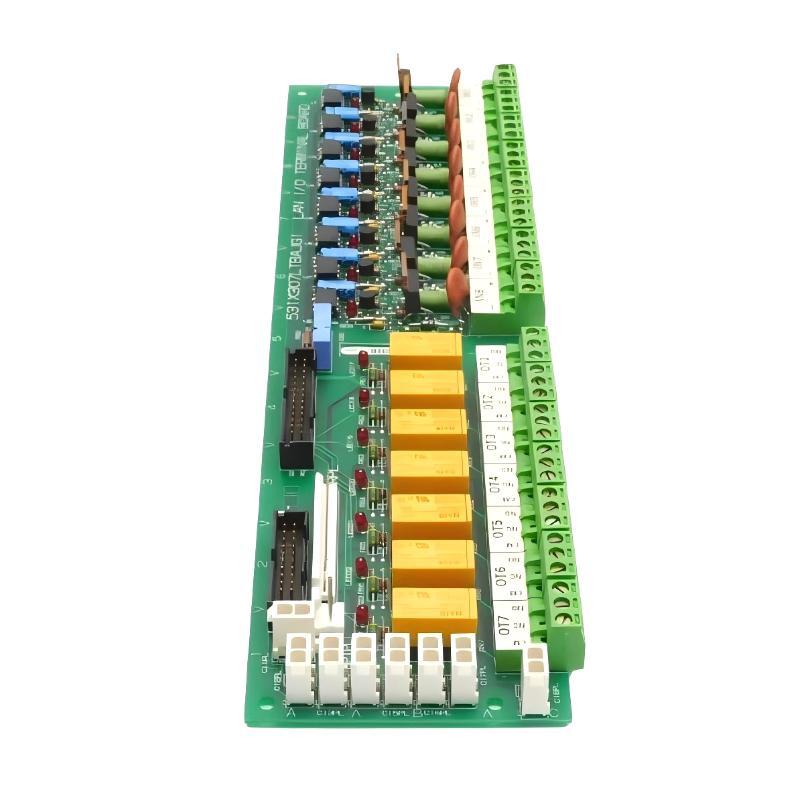
The GE 531X307LTBAJG1 LAN I/O Terminal Board installation requires careful verification of field input wiring, relay output connections, and communication interfaces before the drive or exciter system is energized. Designed for GE 531X drive and exciter control applications, this terminal board provides an interface between external control devices and the internal drive control architecture. Its eight configurable input channels and seven low-voltage, low-current Form C relay output connections allow field signals to be transferred between the cabinet and the control electronics.
Unlike a conventional standalone PLC I/O module, the GE 531X307LTBAJG1 works as part of the host drive control system. Successful installation therefore depends on the correct board revision, connector arrangement, signal voltage, and connection to the associated NTB/3TB terminal board and drive control board.
GE 531X307LTBAJG1 Installation Overview and System Role
The 531X307LTBAJG1 is commonly identified as a LAN Terminal Board (LTB). It is installed inside the applicable GE drive or exciter cabinet and provides electrical interfaces for external devices such as:
- Industrial pushbuttons and selector switches.
- Drive enable and interlock circuits.
- Contactor control interfaces.
- Panel indicator lights.
- External operating status signals.
- Relay-based control and monitoring circuits.
The board receives field input signals and converts compatible input levels into 24 VDC logic signals for the drive control electronics. Its communication and signal distribution arrangement also connects with the associated terminal and control boards.
GE 531X307LTBAJG1 Input and Output Architecture
The G1 hardware configuration provides eight configurable 24 VDC control input plugs, identified as CI1PL through CI8PL. It also includes eight input terminal sets for compatible AC or DC field signals.
The output section contains seven low-voltage, low-current Form C relay contact connections. These outputs are identified as OT1 through OT7, with three contact terminals associated with each output.
- Input channels: Eight field input terminal sets.
- Input voltage: Compatible 24–240 V AC/DC signals, subject to the applicable circuit specifications.
- Logic conversion: Field input signals are converted into 24 VDC logic levels.
- Programmable input plugs: CI1PL–CI8PL.
- Relay outputs: Seven Form C contact outputs.
- Communication interface: Associated 8PL connection and drive control system interfaces.
GE 531X307LTBAJG1 Installation Preparation and Hardware Inspection
Before installing the board, inspect the existing cabinet configuration rather than relying only on the replacement part number. Legacy GE drive systems may contain different terminal board revisions, and apparently similar boards do not necessarily have identical connector arrangements.
Board Revision Verification
Confirm that the replacement board is specifically identified as GE 531X307LTBAJG1. The G1 revision is important because its connector configuration includes the 8PL connection and CI1PL–CI8PL input plugs. These features are not present on the corresponding G2 configuration.
Substituting a different revision without checking the existing wiring can result in missing connections or incompatible field signal arrangements.
Physical Inspection Checklist
- Check the PCB for cracks, damaged tracks, or signs of overheating.
- Inspect terminal blocks for loose or damaged contact points.
- Verify that plug connectors are correctly seated.
- Check ribbon cable connectors for bent pins or damaged insulation.
- Inspect relay areas for discoloration or evidence of excessive heat.
- Confirm that the mounting points are mechanically secure.
Do not install a board showing obvious physical damage until its condition has been assessed.
GE 531X307LTBAJG1 Cabinet Wiring and Signal Connections
Wiring quality has a direct effect on the reliability of the GE 531X307LTBAJG1. Since the board interfaces with external AC/DC signals and internal logic circuits, signal routing and grounding should be checked before connecting the field wiring.
Field Input Wiring Procedure
Identify the input terminal designations IN1 through IN8 and compare them with the original cabinet wiring diagram. Each input should be traced to its corresponding field device.
- Disconnect and isolate the applicable power sources.
- Identify the incoming field signal and its nominal voltage.
- Check the polarity of DC input circuits.
- Confirm that AC input circuits are connected only to compatible G1 input terminals.
- Inspect the wiring insulation and terminal condition.
- Connect each conductor according to the original GE system diagram.
- Verify the completed connections before energization.
The board supports a broad field input voltage range, but this does not mean that every input circuit can be wired interchangeably. Follow the original circuit documentation and the specified input ratings.
GE 531X307LTBAJG1 Relay Output Connections
The OT1–OT7 output connections use Form C relay contacts. These contacts provide switching interfaces for compatible external control circuits.
Before connecting a load, identify the normally open, normally closed, and common contact terminals from the applicable board documentation. Verify the electrical characteristics of the load, including its operating voltage, current, and inductive behavior.
Never assume that the relay contact rating is equivalent to the rating of the external device being controlled. Contact protection and suppression requirements must be considered when switching inductive loads.
Ribbon Cable and Internal Board Connections
The 531X307LTBAJG1 uses plug-in connections to exchange signals with associated drive control components. The 8PL interface is particularly important for the G1 configuration.
During installation, check the cable orientation, connector keying, pin condition, and mechanical retention. Keep signal ribbon cables separated from high-current power conductors to reduce electromagnetic interference and unwanted signal coupling.
GE 531X307LTBAJG1 Setup and Commissioning Strategy
Unlike a programmable PLC CPU, the GE 531X307LTBAJG1 does not provide conventional user-adjustable hardware calibration. Commissioning is primarily concerned with correct wiring, signal verification, relay operation, and integration with the host drive control system.
Initial Electrical Verification
Before applying operating power, verify the following conditions:
- All field wiring matches the approved drawings.
- Input signal voltages are within the permitted range.
- Relay output circuits are connected to compatible loads.
- Ribbon cables are installed in their correct positions.
- Board mounting and insulation clearances are satisfactory.
- There are no unintended shorts between adjacent terminals.
Input Signal Commissioning
Apply an approved test signal to one input channel at a time. Observe the corresponding input indicator and compare its response with the expected control logic state.
The board provides LED indications for the input channels. LED1–LED8 are associated with input source conditions. These indicators are useful for distinguishing an absent field signal from a downstream control problem.
For example, if a 24 VDC signal is applied to IN3 but the expected input indication does not appear, the commissioning engineer should check the field supply, conductor continuity, terminal connection, and input circuit before suspecting a board failure.
Relay Output Commissioning
Test each relay output using an approved control sequence and a suitable measurement instrument. Confirm that the expected contact changes state when the associated relay is energized.
Relay status indicators LED17–LED23 correspond to relay energization conditions RX1–RX7. Compare these indications with the actual relay contact behavior.
GE 531X307LTBAJG1 System Configuration and Integration
The terminal board must operate in coordination with the host drive control electronics. A correct installation requires more than simply mounting the PCB and reconnecting the wires.
The commissioning engineer should establish the relationship between:
- External field switches and interlocks.
- IN1–IN8 input channels.
- CI1PL–CI8PL programmable input connections.
- OT1–OT7 relay output contacts.
- The associated NTB/3TB terminal board.
- The drive control board and internal signal distribution interface.
System Configuration should be checked against the actual application logic. For example, a drive enable signal may be physically present at the terminal board but still fail to enable operation if an associated interlock or control condition remains unsatisfied.
GE 531X307LTBAJG1 Commissioning Example and Engineering Validation
Illustrative engineering scenario: During the commissioning of a legacy GE drive cabinet, an external interlock signal is expected to reach the drive control system through the LAN Terminal Board.
The technician applies a compatible 24 VDC signal to the designated input circuit. However, the control system does not recognize the expected interlock state.
Rather than replacing the terminal board immediately, the engineer follows the signal path:
- Measure the field supply voltage at the source.
- Verify the voltage at the terminal board input.
- Check the corresponding input LED.
- Inspect the input connector and associated ribbon cable.
- Compare the observed status with the drive control logic.
In this illustrative case, the input voltage is present at the source but is missing at the board terminal because of a loose conductor. After correcting the termination, the input indicator responds normally and the control system recognizes the interlock signal.
This example demonstrates why signal-path verification should precede component replacement during GE 531X307LTBAJG1 commissioning.
GE 531X307LTBAJG1 Installation Technical FAQs
What is the main function of the GE 531X307LTBAJG1?
It is a LAN I/O Terminal Board that interfaces external field devices with the control electronics of compatible GE drive and exciter systems.
Is the GE 531X307LTBAJG1 a conventional PLC I/O module?
No. It is a drive control terminal board rather than a standalone PLC module. It performs field signal interfacing and relay-related control functions within the host system.
How many input channels does the 531X307LTBAJG1 provide?
The G1 configuration provides eight input terminal sets and eight configurable 24 VDC input plugs identified as CI1PL through CI8PL.
What input voltage does the GE 531X307LTBAJG1 support?
The input terminal circuits support compatible 24–240 V AC/DC signals. The exact electrical requirements should be checked against the applicable circuit documentation.
How many relay outputs are available?
The board provides seven low-voltage, low-current Form C relay contact outputs, identified as OT1 through OT7.
Does the GE 531X307LTBAJG1 require software programming?
The terminal board does not function as an independent programmable controller. Its operation depends on the configuration and control logic of the associated GE drive system.
Can a G2 terminal board replace the G1 version directly?
Not necessarily. The G2 configuration omits the 8PL connector and CI1PL–CI8PL input plugs. Existing wiring and application requirements must be checked before considering a revision substitution.
What do the input LEDs indicate?
LED1–LED8 provide visual indications associated with the input circuits, helping technicians identify whether an input source is present.
What should be checked before energizing the board?
Verify the board revision, input voltage, terminal wiring, ribbon cable orientation, relay load compatibility, and cabinet grounding arrangements.
Can the GE 531X307LTBAJG1 operate without the associated drive control board?
It should not be treated as an independent control device. Its intended operation depends on the associated drive control architecture and internal connections.
GE 531X307LTBAJG1 Installation Conclusion and Overall Technical Assessment
The GE 531X307LTBAJG1 LAN I/O Terminal Board is an important interface component in compatible GE drive and exciter installations. Its eight input channels, G1-specific configurable input connectors, and seven Form C relay outputs support the exchange of field control signals between external equipment and the internal drive control system.
Reliable installation depends on revision identification, accurate wiring, correct input voltage selection, secure ribbon cable connections, and systematic commissioning. Particular attention should be given to the differences between G1 and G2 hardware because their connector configurations are not identical.
For maintenance engineers working with legacy GE drive systems, a structured Installation Guide and commissioning process can reduce wiring errors, prevent unnecessary board replacement, and improve long-term control system reliability.