
NewsNEWCENTER
Featured products

Contact Us
Emerson A6500-LC LVDT Converter Installation and Commissioning Guide
2026-11-05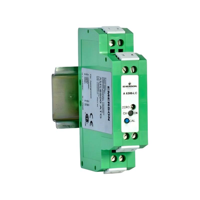
1. Product Overview
The Emerson A6500-LC LVDT Converter is a single-channel signal conditioning device designed for use with inductive half-bridge displacement sensors and Linear Variable Differential Transformer (LVDT) sensors. It is part of the Emerson AMS 6500 ATG Advanced Turbo Guard machinery monitoring platform. The converter supplies excitation voltage to the connected sensor and converts the sensor’s displacement-proportional signal into a voltage output suitable for the A6500-UM Universal Measuring Card. This arrangement allows linear displacement measurements to be integrated into a machinery monitoring and protection system. The A6500-LC is used in applications involving turbine casing expansion, differential expansion, axial displacement, and other linear position measurements. Correct installation is important because sensor compatibility, wiring polarity, grounding, calibration, and measuring direction directly affect the accuracy of the resulting measurement. This guide explains the preparation, mounting, wiring, configuration, and commissioning of the Emerson A6500-LC.
2. Technical Specifications
| Parameter | Specification | |—|—| | Manufacturer | Emerson | | Model | A6500-LC | | Product Type | LVDT Converter | | System Platform | AMS 6500 ATG Advanced Turbo Guard | | Input | Inductive half-bridge and compatible LVDT sensors | | Number of Channels | 1 | | Compatible Sensor Families | PR 9350 series, PR 9340/12, PR 9314/41, subject to the specified configuration | | Sensor Excitation | Approximately 2.2 Vrms at 5 kHz | | Supply Voltage | +22.5 to +32 VDC | | Current Consumption | Less than 30 mA | | Standard Output Range | +2 to +18 V | | Output Frequency Range | 0 to 10 Hz (-3 dB) | | Measurement Accuracy | Less than ±2% of measuring range under specified conditions | | Output Jitter | Less than 10 mV peak-to-peak | | Switch-On Time | Approximately 200 ms | | Mounting | DIN rail, NS 35/7.5 recommended | | Protection Class | IP20 | | Operating Temperature | -35°C to +75°C | | Storage Temperature | -35°C to +85°C | | Relative Humidity | 5% to 95%, non-condensing | | Dimensions | 20.0 × 79.5 × 69.5 mm | | Net Weight | Approximately 65 g | The measuring range and output voltage swing depend on the connected sensor model. Confirm the exact sensor and converter configuration before commissioning.
3. Understanding the A6500-LC Signal Conversion Process
An LVDT sensor converts mechanical displacement into an electrical signal. The A6500-LC supplies the required excitation and conditions the resulting signal so that the A6500-UM can process it. A typical signal path is:
Linear Displacement
        |
        v
LVDT / Inductive Half-Bridge Sensor
        |
        v
Emerson A6500-LC Converter
        |
        | Standard Voltage Signal
        v
A6500-UM Universal Measuring Card
        |
        v
AMS 6500 ATG Monitoring System
        |
        v
Measurement Display and Alarm Evaluation
The converter and its connected sensor form a measuring chain. Replacing the sensor requires recalibration of the converter according to the approved procedure. A sensor replacement should therefore be treated as a measurement-system maintenance activity rather than a simple wiring change.
4. Pre-Installation Preparation
4.1 Verify Sensor Compatibility
Before installation, identify the exact sensor model. The A6500-LC supports compatible inductive half-bridge and LVDT sensors, including specified PR 9350 series sensors and other supported models. Do not assume that every LVDT sensor can be connected directly. Verify the sensor’s electrical characteristics, measuring range, wiring arrangement, and calibration requirements.
4.2 Check the Power Supply
Prepare a suitable safety extra-low-voltage or protected extra-low-voltage DC supply within the specified +22.5 to +32 V range. The converter includes overvoltage protection, but the supply must still comply with the manufacturer’s requirements. Use an appropriate SELV/PELV power supply and provide a suitable disconnecting means in the end-use installation.
4.3 Prepare the Installation Enclosure
The A6500-LC is an IP20 device intended for installation inside a suitable enclosure. The enclosure should protect the converter and operator from environmental and electrical hazards. A DIN rail of type NS 35/7.5 is recommended. Provide adequate mounting clearance and ensure that the installation environment remains within the specified temperature and humidity limits.
4.4 Prepare Tools and Documentation
Prepare the following: – Approved A6500-LC operating documentation. – Sensor model and wiring information. – AMS 6500 rack and A6500-UM configuration drawings. – Suitable insulated screwdrivers. – Wire preparation tools and ferrules. – Digital multimeter with suitable measurement ranges. – ESD protection equipment. – Commissioning and calibration records.
5. Installation Safety Requirements
The A6500-LC must be installed and serviced by trained personnel. Incorrect polarity or improper installation can generate false measurement signals that do not represent the actual mechanical displacement. Observe these precautions: – Isolate the relevant power supply before wiring or modifying connections. – Verify that the supply is within the permitted voltage range before energizing. – Do not connect the converter to a hazardous-voltage circuit. – Use cables rated for the installation temperature range. – Install the converter inside an appropriate enclosure. – Follow the site’s grounding and shielding requirements. – Avoid handling exposed electronic connections without ESD protection. – Confirm the wiring against the exact terminal diagram before applying power.
6. Mounting the A6500-LC on a DIN Rail
6.1 Inspect the Mounting Location
Confirm that the selected enclosure provides adequate space for the converter, wiring, and cable routing. The recommended mounting rail is NS 35/7.5. Ensure that the mounting location is not exposed to excessive vibration, moisture, contamination, or temperatures outside the permitted operating range.
6.2 Install the Converter
Position the A6500-LC on the DIN rail according to its housing design and the manufacturer’s mounting instructions. Confirm that the retaining mechanism engages correctly. Do not force the housing or apply excessive mechanical pressure. Check that the converter is securely mounted and that its terminals remain accessible for wiring and maintenance.
6.3 Check Installation Clearance
Maintain sufficient clearance for conductors and terminal access. Arrange wiring so that it does not place unnecessary mechanical stress on the screw terminals.
7. Electrical Wiring and Connection Requirements
Correct wiring is essential for reliable displacement measurement. The sensor connection, converter supply, and output signal must follow the approved A6500-LC and rack connection diagrams.
7.1 Converter Power Supply
Connect the DC supply to the designated power terminals. Verify the terminal identification and polarity using the exact product wiring diagram. The specified supply voltage is +22.5 to +32 VDC, with current consumption below 30 mA. Do not reverse the supply polarity or assume terminal positions based on another converter model.
7.2 Sensor Connection
Connect the compatible LVDT or inductive half-bridge sensor to the designated sensor terminals. Confirm the sensor wiring arrangement and ensure that the cable conductors are correctly identified. The A6500-LC provides approximately 2.2 Vrms excitation at 5 kHz for the sensor. Use the sensor type and wiring configuration specified for the application.
7.3 Output Signal Connection
Connect the converter output to the corresponding input of the A6500-UM Universal Measuring Card. The standard signal output range is +2 to +18 V. The output wiring must match the selected input channel and rack configuration. Verify the receiving card’s input requirements before energizing the system.
7.4 Cable Selection and Shielding
For the rack connection, Emerson recommends twisted-pair, double-screened cables such as LiYCY-CY. Separate the converter supply conductors from the sensor signal conductors where specified by the wiring arrangement. Maintain proper cable shielding and grounding according to the approved EMC installation design. Incorrect screen termination can introduce interference or unstable measurements.
8. Connecting the A6500-LC to the AMS 6500 Rack
When the converter is connected to an AMS 6500 system rack, the sensor signal and converter supply are routed to the corresponding rack terminals. For the rack connection arrangement described in the system documentation: | Function | A6500-LC Terminal | Rack Connection | |—|—|—| | Converter supply | Terminal 1 | Corresponding channel supply input | | Converter supply return | Terminal 2 | Corresponding channel supply return | | Sensor signal | Terminal 3 | Corresponding channel signal input 1 | | Sensor signal | Terminal 4 | Corresponding channel signal input 2 | For the documented rack wiring example, channel 1 uses XRx1.1 and XRx1.2 for the sensor signal, and XRx1.3 and XRx1.4 for converter supply. Channel 2 uses the corresponding XRx2 connections. These designations are rack-specific. Verify the exact backplane, slot, and terminal drawing for the installed rack before making connections.
9. A6500-UM Configuration
After the converter has been installed and wired, configure the A6500-UM according to the connected sensor and required measurement application. Important configuration parameters include: – Sensor model. – Converter type. – Measuring range. – Measurement direction. – Input scaling and linearization. – Engineering units. – Alarm limits, where applicable. The selected sensor and converter combination must match the physical installation. An incorrect sensor selection or measuring direction can produce inaccurate readings or reverse the displayed displacement direction.
10. Commissioning and Calibration
10.1 Initial Power-Up
Before energizing the converter, inspect the power, sensor, and output connections. Confirm that all conductors are correctly terminated and that no exposed wire strands can cause short circuits. Apply the approved supply voltage and allow approximately 200 ms for the converter to switch on. Verify the output signal using the approved commissioning procedure.
10.2 Configure the Measuring Range
Select the correct sensor type and measuring range in the A6500-UM configuration. The A6500-LC supports several sensor-dependent measuring ranges, so the configured range must match the actual sensor.
10.3 Verify Measurement Direction
Move the measured object or use an approved calibration method to verify that the displayed displacement changes in the intended direction. If the reading moves in the opposite direction, check the configured measuring direction and sensor wiring against the approved documentation.
10.4 Calibrate the Measuring Chain
The converter and sensor should be calibrated as one measuring chain. Follow the specified calibration procedure for the selected sensor. If a sensor is replaced, recalibrate the converter. Do not assume that the previous calibration remains valid after a sensor change.
10.5 Verify Output Signal
Confirm that the A6500-LC output is within the expected voltage range for the selected sensor and measuring position. Compare the measured output with the expected calibration values. Record the final configuration and commissioning results.
11. Common Installation Problems
| Problem | Possible Cause | Recommended Action | |—|—|—| | No output signal | Missing supply, incorrect wiring, or sensor circuit problem | Verify supply, sensor connection, and output wiring | | Incorrect displacement reading | Wrong sensor selection or scaling | Check A6500-UM configuration | | Reversed measurement direction | Incorrect direction setting or wiring arrangement | Verify direction configuration and wiring | | Unstable measurement | Poor shielding, grounding, or loose connections | Inspect cable routing and terminations | | Output outside expected range | Incorrect sensor range or calibration | Confirm sensor model and recalibrate | | Measurement changes after sensor replacement | Previous calibration no longer valid | Recalibrate the complete measuring chain | | Converter does not operate | Supply voltage outside the permitted range or hardware fault | Check the DC supply and inspect the module |
12. Preventive Maintenance
To maintain reliable measurement performance: – Inspect DIN-rail mounting and enclosure condition. – Check screw terminals for secure connections. – Inspect sensor cables for damage and contamination. – Maintain proper shielding and grounding. – Verify the DC supply during scheduled maintenance. – Keep the sensor model and calibration information documented. – Recalibrate after sensor replacement or relevant mechanical changes. – Review measurement trends for unexplained deviations. – Keep a backup of the A6500-UM configuration.
13. Frequently Asked Questions
What is the Emerson A6500-LC used for?
The A6500-LC converts displacement-proportional signals from compatible LVDT and inductive half-bridge sensors into voltage signals suitable for the A6500-UM Universal Measuring Card.
Is the A6500-LC a multi-channel converter?
No. The A6500-LC is a single-channel converter. Each unit conditions the signal from one compatible sensor measuring chain.
Which sensors can be connected to the A6500-LC?
It supports specified inductive half-bridge and LVDT sensors, including compatible PR 9350 series models and other documented sensor types. Confirm the exact sensor compatibility and wiring before installation.
Does the A6500-LC require an external power supply?
Yes. It requires a DC supply between +22.5 and +32 VDC. The specified current consumption is less than 30 mA.
What happens if the connected sensor is replaced?
The converter and sensor form one measuring chain. Replacing the sensor requires recalibration to ensure that the displacement measurement remains accurate.
Can the A6500-LC be installed directly in an exposed environment?
It has an IP20 protection rating and is intended for installation inside a suitable enclosure. The enclosure should provide the necessary protection for the operating environment and personnel.
14. Technical Summary
The Emerson A6500-LC LVDT Converter is a single-channel signal conditioning device for compatible inductive half-bridge and LVDT displacement sensors. It supplies sensor excitation and converts displacement-related signals into a voltage output suitable for the A6500-UM Universal Measuring Card in the AMS 6500 ATG system. Reliable operation depends on correct sensor selection, DIN-rail mounting, supply polarity, field wiring, grounding, measuring-range configuration, and calibration. Treating the converter and sensor as one measuring chain is particularly important when replacing sensors or modifying the measurement installation. By following the correct installation and commissioning procedures, maintenance personnel can help maintain accurate linear displacement measurements and dependable machinery monitoring.