
NewsNEWCENTER
Featured products

Contact Us
Emerson A6500-LC LVDT Converter Troubleshooting and Fault Diagnosis Guide
2026-11-05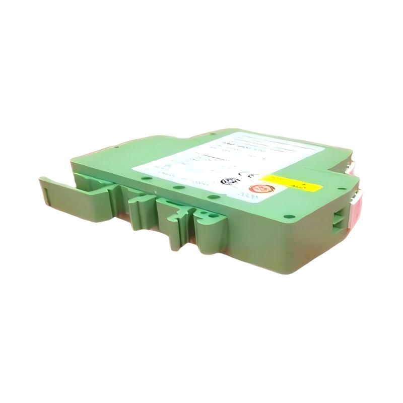
1. Introduction
The Emerson A6500-LC LVDT Converter is a single-channel signal conditioning device used with compatible inductive half-bridge and Linear Variable Differential Transformer (LVDT) sensors. It is designed for integration with the A6500-UM Universal Measuring Card in the Emerson AMS 6500 ATG machinery monitoring system. The converter supplies excitation voltage to the connected sensor and transforms its displacement-related signal into a DC voltage suitable for measurement and monitoring. Typical applications include turbine casing expansion, differential expansion, and other linear displacement measurements in rotating machinery. When an A6500-LC produces an abnormal measurement, the problem may originate from the sensor, sensor wiring, power supply, converter calibration, output connection, or A6500-UM configuration. Replacing the converter without checking these components can result in unnecessary maintenance and repeated faults. This guide describes practical troubleshooting procedures for the Emerson A6500-LC, including LED status interpretation, power checks, sensor inspection, output measurement, calibration, and post-repair verification.
2. A6500-LC Technical Characteristics
| Parameter | Description | |—|—| | Manufacturer | Emerson | | Model | A6500-LC | | Product Type | LVDT Converter | | System Platform | AMS 6500 ATG | | Measuring Channels | 1 | | Sensor Types | Compatible LVDT and inductive half-bridge sensors | | Supported Sensor Families | PR 9350 series, K20315 series, PR 9314/41, and other specified compatible sensors | | Sensor Excitation | Approximately 2.2 Vrms at 5 kHz | | Supply Voltage | +22.5 to +32 VDC | | Current Consumption | Less than 30 mA | | Standard Output Range | +2 to +18 V, depending on sensor and calibration | | Measuring Sensitivity | Fixed sensitivity of 4 V/(100 mV/V) for the applicable configuration | | Output Frequency Range | 0 to 10 Hz (-3 dB) | | Accuracy | Less than ±2% of measuring range under specified conditions | | Output Jitter | Less than 10 mV peak-to-peak | | Mounting | DIN rail | | Protection Class | IP20 | The A6500-LC supports fixed-sensitivity and factory-calibrated configurations. These configurations have different commissioning and adjustment requirements. Always identify the installed configuration before performing calibration or functional checks.
3. Common A6500-LC Fault Symptoms
| Symptom | Possible Cause | Recommended Check | |—|—|—| | Red Channel OK LED | Sensor supply, sensor current, signal, or output supervision outside permitted limits | Check power, sensor wiring, and sensor condition | | Orange Channel OK LED | Channel OK supervision disabled | Check the CAL button and wire bridge | | No output voltage | Missing supply, disconnected wiring, or converter fault | Measure supply and output voltage | | Output below 1.5 V | Converter supervision has detected an abnormal condition | Inspect the sensor and converter circuit | | Unstable displacement reading | Loose wiring, electrical interference, or unstable sensor signal | Inspect cables, shielding, and sensor installation | | Incorrect measurement value | Incorrect sensor selection, range, or calibration | Verify sensor compatibility and A6500-UM configuration | | Reversed measurement direction | Incorrect measurement direction or sensor wiring | Check the approved sensor and configuration documentation | | Measurement changes after sensor replacement | Existing calibration no longer matches the sensor | Recalibrate the complete measuring chain | | A6500-UM reports a channel fault | Abnormal converter output or input configuration | Check the A6500-LC output and measuring card |
4. Safety Precautions Before Troubleshooting
The A6500-LC may be part of a machinery protection system. An incorrect measurement can affect turbine expansion monitoring and other important operating limits. Before carrying out troubleshooting: – Inform the responsible plant and instrumentation personnel. – Determine whether the affected measurement participates in an active machinery protection function. – Obtain authorization before deactivating any protection function. – Follow the site’s lockout/tagout and electrical isolation procedures. – Use suitable insulated test leads and a properly rated multimeter. – Apply ESD protection when handling the converter. – Do not disconnect sensor wiring or modify calibration settings without an approved procedure. – Reactivate any temporarily disabled protection function immediately after the work is completed and verify its availability. Do not treat a red or abnormal LED as permission to bypass the measurement channel. First establish whether the indication represents an actual equipment condition or a measurement-system fault.
5. Understanding the Channel OK LED
The A6500-LC has a front-panel Channel OK LED that indicates the status of its internal supervision function. | LED Color | Indication | Troubleshooting Action | |—|—|—| | Green | Supervised values are within the permitted limits and the output is within the sensor working range | Normal status; continue with measurement verification if necessary | | Red | One or more supervised values are outside the permitted limits; converter output is set below 1.5 V | Inspect supply voltage, sensor wiring, sensor current, and signal conditions | | Orange | Channel OK supervision is disabled; the output is not automatically forced below 1.5 V by the supervision function | Check whether the CAL button is pressed or the supervision wire bridge is open | The orange indication is particularly important during maintenance. It does not mean that the sensor system has passed all supervision checks. It indicates that the Channel OK function has been disabled. After calibration or testing, restore the Channel OK function and confirm that the LED returns to the appropriate operating state.
6. Troubleshooting Power Supply Problems
An incorrect power supply can prevent the A6500-LC from operating normally or cause abnormal output behavior.
6.1 Measure the Supply Voltage
For the documented functional check, connect a suitable DC voltmeter between: – Terminal 1: +24 VDC – Terminal 2: GND The measured supply voltage should be within +22.5 to +32 VDC. If the voltage is outside this range, inspect the external power supply, wiring, terminal connections, and any associated rack power distribution components.
6.2 Inspect Power Connections
Check for loose screw terminals, damaged conductors, corrosion, and incorrect polarity. Confirm that the supply remains stable under normal operating conditions. If the supply is correct at the source but abnormal at the converter, investigate voltage drop or wiring resistance between the power source and the A6500-LC.
6.3 Distinguish Supply Problems from Converter Faults
Do not replace the converter immediately if the measured supply is abnormal. Restore the correct supply first, then check the Channel OK LED and output voltage again. If the supply is stable and the converter still reports an abnormal condition, continue with sensor and signal checks.
7. Troubleshooting LVDT Sensor and Wiring Problems
The sensor and converter operate as a combined measuring chain. Problems involving the sensor, cable, or connections can cause an incorrect output even when the converter itself is functioning correctly.
7.1 Inspect the Sensor
Check the connected sensor for: – Physical damage to the housing or sensing mechanism. – Mechanical obstruction or restricted movement. – Loose mounting hardware. – Contamination or moisture exposure. – Incorrect installation position. – Damage to the sensor cable or connector. For linear displacement transducers, confirm that the moving element can travel through the intended measuring range without mechanical interference.
7.2 Check Sensor Wiring
Inspect the conductors between the sensor and A6500-LC. Check that each wire is connected to the correct terminal according to the sensor-specific wiring diagram. Look for loose terminals, broken conductors, incorrect connections, and damaged cable insulation. Do not assume that two sensors with similar connector arrangements use identical terminal assignments.
7.3 Check Sensor Compatibility
Confirm that the connected sensor belongs to a supported sensor family and matches the converter’s electrical and calibration requirements. The A6500-LC can be used with compatible PR 9350 linear displacement transducers, K20315 sensor sets, and specified inductive half-bridge or LVDT sensors, including PR 9314/41. If a sensor has been replaced with a different model, verify that the measuring range and calibration data are suitable for the new combination.
7.4 Inspect Cable Shielding
Poor shielding or incorrect cable routing may introduce electrical interference into the measurement circuit. Inspect the cable screen and grounding arrangement against the approved installation drawing. Keep sensor signal cables away from high-current power cables and other strong interference sources where practical.
8. Troubleshooting Abnormal Output Voltage
The A6500-LC converts the sensor signal into a DC voltage output. Measuring this output is one of the most useful ways to distinguish sensor-related problems from converter or downstream input problems.
8.1 Measure the Converter Output
For the documented functional check, connect a suitable DC voltmeter between: – Terminal 3: Signal output – Terminal 4: GND Move the sensor tracing pin through defined positions within its measuring range. Record the output voltage at each position. The expected voltage depends on the sensor type and calibration. Compare the measured values with the applicable sensor and converter calibration information.
8.2 Investigate an Output Below 1.5 V
When the internal supervision function detects an abnormal condition, the converter output is set below 1.5 V. If this occurs, check: 1. Whether the supply voltage is within specification. 2. Whether the sensor wiring is correctly connected. 3. Whether the sensor supply and signal conditions are normal. 4. Whether the sensor or cable is damaged. 5. Whether the converter has an internal fault. An output below 1.5 V should not be interpreted as a normal displacement measurement.
8.3 Investigate an Output That Does Not Change
If the output remains almost constant while the sensor moves through its measuring range, inspect the mechanical movement, sensor connection, and converter input. A disconnected or damaged sensor circuit may prevent the converter from producing the expected displacement-related output. If the sensor and wiring are confirmed to be correct, perform the approved converter function check.
8.4 Investigate an Output That Is Unstable
An unstable output may be caused by: – Intermittent sensor wiring. – Loose screw terminals. – Electrical interference. – Mechanical vibration or movement of the sensor mounting. – A defective sensor. – An unstable DC power supply. Compare the output voltage with the actual sensor position. If the sensor is mechanically stationary but the voltage fluctuates, concentrate on the electrical signal path and converter.
9. Calibration and Zero-Point Problems
Calibration is an important part of A6500-LC maintenance. The correct procedure depends on whether the converter uses fixed sensitivity or has been factory calibrated for a particular sensor.
9.1 Identify the Converter Calibration Type
Before adjustment, check the converter identification and calibration records. Do not assume that a factory-calibrated unit can be adjusted in the same way as a fixed-sensitivity unit. For a factory-calibrated measuring chain, the sensor and converter are calibrated together. Replacing the sensor requires recalibration of the A6500-LC.
9.2 Check the Electrical Center Position
For the documented fixed-sensitivity commissioning procedure, the electrical center position can be checked using the converter’s output voltage. The procedure involves: 1. Connecting a suitable DC voltmeter to the signal output. 2. Removing the sensor tracing pin from the measuring mechanism as specified by the procedure. 3. Temporarily disabling Channel OK supervision using the CAL button. 4. Confirming the orange LED indication. 5. Adjusting the zero potentiometer until the output reads 10 VDC. 6. Restoring Channel OK supervision. 7. Positioning the tracing pin so that the output reads 10 VDC. This procedure must only be carried out by qualified personnel under the approved commissioning and machinery protection arrangements.
9.3 Check the Mechanical Measuring Range
After establishing the center position, verify that the sensor can travel through its intended measuring range. Use a suitable ruler or calibrated displacement reference to move the tracing pin through defined positions. Record the corresponding output voltage and compare it with the expected values for the installed sensor.
9.4 Recalibrate After Sensor Replacement
A replacement sensor may have different sensitivity or measuring characteristics. If the A6500-LC was factory calibrated for the original sensor, replacing that sensor changes the measuring chain. Follow the required calibration procedure and update the A6500-UM linearization settings as necessary.
10. Troubleshooting A6500-UM Measurement Errors
Sometimes the A6500-LC output is correct, but the displayed measurement in the AMS 6500 ATG system is incorrect. In this situation, inspect the receiving A6500-UM configuration. Check the following parameters: – Selected sensor type. – Converter selection. – Measuring range. – Linearization points. – Engineering units. – Measurement direction. – Channel assignment. The A6500-UM must be configured for the actual sensor and converter combination. For linear displacement measurements, incorrect linearization can result in an inaccurate displayed position even when the A6500-LC produces a stable output voltage. Where possible, compare the converter’s measured output voltage with the value displayed by the A6500-UM. If the converter output is correct but the displayed displacement is not, investigate scaling and linearization before replacing the converter.
11. Functional Check and Fault Isolation Procedure
A systematic functional check can help determine whether an abnormal measurement originates in the supply, sensor, or converter. | Step | Inspection | Expected Result | |—|—|—| | 1 | Measure supply between terminals 1 and 2 | +22.5 to +32 VDC | | 2 | Inspect sensor and cable connections | Correct wiring and secure connections | | 3 | Check Channel OK LED | Green during normal supervised operation | | 4 | Measure output between terminals 3 and 4 | Voltage appropriate for sensor position and calibration | | 5 | Move the sensor through defined positions | Output changes according to the calibration characteristics | | 6 | Compare output with A6500-UM measurement | Displayed value corresponds to the configured scaling | | 7 | Restore supervision and protection functions | Normal operating status confirmed | If the power supply is correct but the output remains abnormal, investigate the sensor and its wiring before condemning the converter. If the sensor and converter output are correct but the system measurement is wrong, check the A6500-UM configuration and linearization.
12. A6500-LC Replacement and Post-Repair Verification
If testing confirms that the converter has an internal hardware fault, replacement may be necessary. Before replacing the unit, record: – Complete model identification. – Sensor model and measuring range. – Converter calibration type. – Existing zero-point setting. – A6500-UM channel configuration. – Linearization points. – Current measurement and alarm status. Install the replacement according to the approved system procedure. Confirm that its configuration and calibration are appropriate for the connected sensor. After replacement: 1. Verify the DC supply voltage. 2. Confirm the sensor connections. 3. Check the Channel OK LED. 4. Measure the converter output voltage. 5. Verify the electrical and mechanical measuring center. 6. Perform the required sensor and converter calibration. 7. Check A6500-UM scaling and linearization. 8. Confirm that the displayed displacement corresponds to the actual sensor position. 9. Verify the required alarm and protection functions. 10. Document the work and restore all temporarily disabled protection functions. Do not return the measurement channel to normal service until the responsible personnel have confirmed that the complete measuring chain operates correctly.
13. Preventive Maintenance Recommendations
The A6500-LC does not require scheduled maintenance according to its operating manual. Periodic function checks are nevertheless useful when unexpected measurements or unusual behavior occur. Recommended maintenance practices include: – Inspect sensor cables and screw terminals during relevant plant maintenance activities. – Confirm that the DC supply remains within the specified range. – Check the Channel OK LED when investigating abnormal measurements. – Keep sensor and converter calibration records. – Recalibrate after sensor replacement. – Maintain a backup of A6500-UM configuration and linearization data. – Inspect sensor mounting and mechanical movement. – Record abnormal output voltage measurements and troubleshooting results.
14. Frequently Asked Questions
What does a red LED on the Emerson A6500-LC mean?
A red Channel OK LED indicates that one or more supervised values are outside their permitted limits. The converter output is set below 1.5 V. Check the supply voltage, sensor wiring, sensor condition, and converter operation.
What does an orange LED indicate?
An orange LED indicates that Channel OK supervision is disabled. This can occur when the calibration button is pressed or the supervision wire bridge is open. Restore supervision after completing the approved calibration or test procedure.
What is the normal A6500-LC power supply voltage?
The specified DC supply range is +22.5 to +32 VDC. The documented functional check measures this voltage between terminals 1 and 2.
Where should the converter output voltage be measured?
For the documented functional check, measure the DC output between terminal 3 and terminal 4. Compare the result with the expected output for the connected sensor and its calibration.
Why does the A6500-LC output change after sensor replacement?
The sensor and converter form a combined measuring chain. A replacement sensor may have different calibration characteristics, so the converter and measurement configuration must be checked and recalibrated as required.
Does the A6500-LC need routine maintenance?
The operating manual states that scheduled maintenance is not required. However, a function check is recommended when unexpected measurement values or unusual behavior occur.
Can the A6500-LC be used without the A6500-UM?
The A6500-LC is designed to provide its conditioned output to the A6500-UM Universal Measuring Card in the AMS 6500 ATG system. Any alternative application requires verification of the receiving device’s electrical and signal requirements.
15. Technical Summary
The Emerson A6500-LC LVDT Converter is a single-channel signal conditioning device for linear displacement measurement in the AMS 6500 ATG machinery monitoring system. Its operation depends on a compatible sensor, correct excitation and power supply, reliable field wiring, appropriate calibration, and accurate A6500-UM configuration. When an abnormal measurement occurs, troubleshooting should begin with the Channel OK LED and DC supply voltage. The next steps are to inspect the sensor circuit, measure the converter output, verify the calibration, and check the receiving measuring card’s scaling and linearization. A structured diagnostic process helps distinguish sensor faults, wiring problems, calibration errors, and converter hardware failures. This approach supports reliable displacement monitoring and helps maintenance personnel avoid unnecessary replacement of functioning components.