

ProductPRODUCT
Featured products
Contact Us
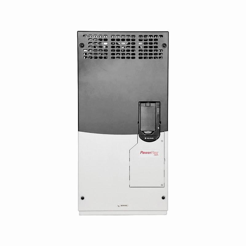
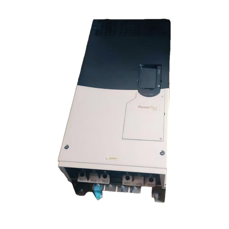
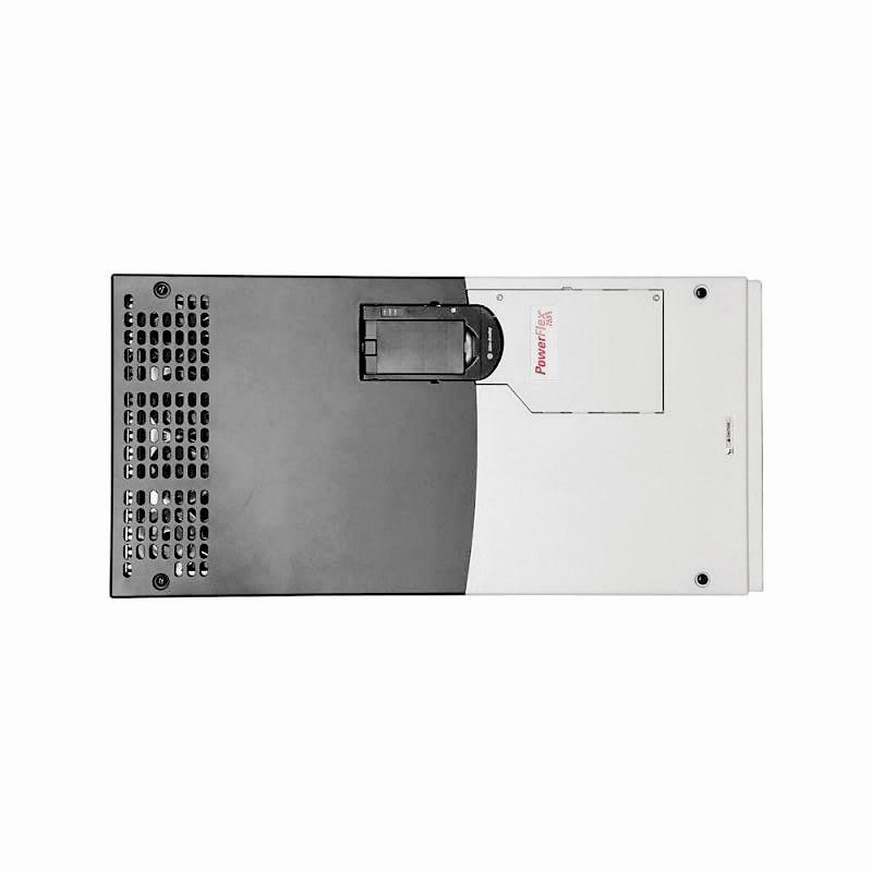
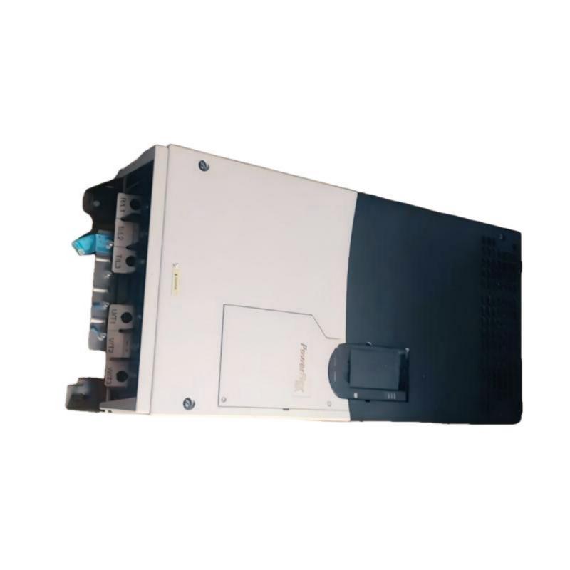
- Allen Bradley
- 20F1AND361JA0NNNNN
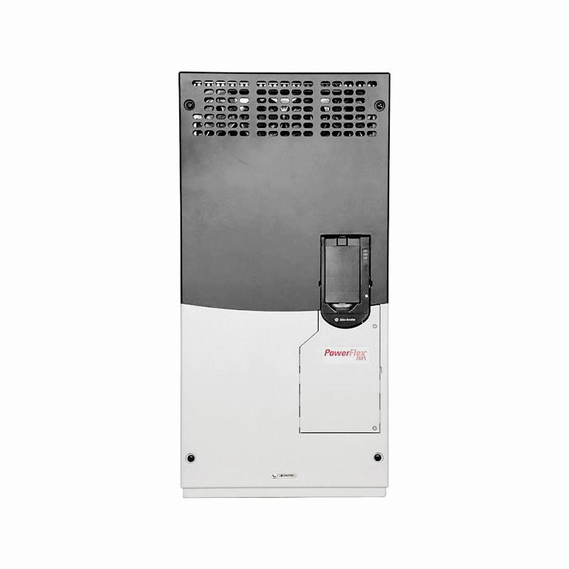
- PowerFlex 753 AC Drive
- USA
- 881.5 x 430 x 349.6 mm
- 72.6 kg
- Xiamen, China
- New & In Stock
- T/T, PayPal, Western Union
- 1 Year
- 1-3 Working Days
- DHL, UPS, TNT, FedEx and EMS.
- 24-Hour Service
- COO
- 5
Our advantage

Global Logistics
We have a 10-year logistics and express cooperation agreement, so our products can be shipped to any place in the world.

Brand new and original
Our products are imported in bulk from the place of origin. Because of the cooperative relationship, our products are all original and 100% new.

24-hour service
We provide 7*24 hours service to our customers. We will be there whenever you need us.

Price advantage
All our products are priced very favorably because we have our own warehouse and supply.
| Company Information | |||
| [email protected] | |||
| Mobile | +8615980777398 | ||
| +8615980777398 | |||
| 15980777398 |
Product Overview
The Allen-Bradley 20F1AND361JA0NNNNN PowerFlex 753 AC Drive is a high-power industrial variable frequency drive designed to control large three-phase AC motors in demanding industrial applications. Manufactured by Rockwell Automation, the PowerFlex 753 family provides adjustable-speed motor control, embedded I/O, and configurable functions for integration into automated production and process-control systems.
Variable frequency drives regulate motor operation by adjusting the frequency and voltage delivered to the motor. This allows large industrial machines to operate according to changing process requirements instead of running continuously at a fixed speed. In suitable applications, adjustable-speed control can improve process coordination, reduce mechanical stress during starting and stopping, and help optimize energy use.
The 20F1AND361JA0NNNNN is a 480 V AC, three-phase model with a rated output current of 361 A. Its published power ratings are 300 HP under normal-duty conditions and 250 HP under heavy-duty conditions. It uses a Frame 7 design and forced-air cooling, making it suitable for high-power motor-control installations where electrical capacity, cabinet design, thermal management, and maintenance access must be carefully planned.
This configuration includes embedded I/O, standard protection, AC input with precharge, no DC terminals, an EMC filter with the common-mode jumper installed, and a dynamic braking transistor. It has an IP20/IP00, NEMA/UL Open Type enclosure configuration and is supplied without a human interface module (HIM).
The full catalog number is important when identifying this drive. Other PowerFlex 753 models may have different voltage classes, current ratings, enclosure types, input arrangements, braking options, and operator interfaces. A replacement should therefore be selected by comparing the complete catalog number and technical configuration rather than relying only on the PowerFlex 753 series name.
Technical Specifications
| Parameter | Specification |
|---|---|
| Brand | Allen-Bradley |
| Manufacturer | Rockwell Automation |
| Model | 20F1AND361JA0NNNNN |
| Product Series | PowerFlex 753 |
| Product Type | AC Drive / Variable Frequency Drive |
| Input Voltage | 480 V AC |
| Input Phase | Three-phase |
| Input Type | AC input with precharge |
| DC Terminals | Not included |
| Rated Output Current | 361 A |
| Normal-Duty Power Rating | 300 HP |
| Heavy-Duty Power Rating | 250 HP |
| Frame Size | Frame 7 |
| Cooling Method | Forced air |
| Control Interface | Embedded I/O |
| Protection Configuration | Standard protection |
| Enclosure Type | IP20/IP00, NEMA/UL Open Type |
| EMC Filtering | Filtered |
| Common-Mode Capacitor Configuration | CM jumper installed |
| Dynamic Braking | Dynamic braking transistor |
| Human Interface Module | Blank; no HIM installed |
| Dimensions Provided | 881.5 × 430 × 349.6 mm |
| Weight Provided | 72.6 kg |
| Lifecycle Status | Active, according to manufacturer product listing |
| Typical Application | High-power industrial AC motor control |
Note: Dimensions and weight are the supplied listing values. Verify the exact drive configuration, dimensional drawing, and shipping weight before panel design or transportation.
Function and Working Principle
The PowerFlex 753 AC drive regulates the electrical power supplied to a three-phase motor. It converts the incoming AC supply into a controlled output and adjusts motor operation according to the selected control method, speed reference, and configured parameters.
1. Variable-Frequency Motor Control
The operating speed of an AC motor is related to the frequency of its electrical supply and the motor’s design. By changing the output frequency, the drive can adjust motor speed to match the requirements of the industrial process.
For example, a large conveyor system may need to operate at different speeds depending on material flow. A pump or fan may need to adjust its output according to process demand. The drive allows the control system to change motor speed without depending entirely on mechanical speed-adjustment equipment.
The actual speed range and motor performance depend on the connected motor, load characteristics, control configuration, and application requirements.
2. High-Current Motor Power Control
With a rated output current of 361 A, this model is intended for substantially larger motor loads than compact industrial drives. Its current capacity is an important selection parameter because motor current determines the electrical loading placed on the drive’s power components.
The 300 HP normal-duty and 250 HP heavy-duty ratings describe different application duty conditions. Heavy-duty applications generally involve more demanding overload requirements, so the lower heavy-duty power rating must be observed when selecting the drive.
Motor nameplate current, operating voltage, overload profile, and ambient conditions should all be considered during engineering.
3. Embedded I/O and Control Coordination
The drive includes embedded I/O for connection to compatible control signals. These interfaces can support coordination with external controllers, interlocks, and machine-control devices.
The exact signal assignments and available functions depend on the drive’s terminal configuration and parameter settings. Engineers should consult the applicable PowerFlex 750 installation and technical documentation before designing control wiring.
4. Dynamic Braking
The 20F1AND361JA0NNNNN configuration includes a dynamic braking transistor. This component is used in a braking circuit to control the connection of an external braking resistor when the application requires energy dissipation during deceleration.
The braking transistor should not be confused with an installed braking resistor. The catalog configuration identifies the transistor, but the required resistor and associated wiring must be evaluated separately.
Applications involving high-inertia loads, rapid stopping, or frequent deceleration may require a carefully engineered braking arrangement. Resistor sizing, duty cycle, thermal limits, and protective measures must follow the manufacturer’s requirements.
5. Precharge Function
The drive uses an AC input with precharge. Precharge limits the initial charging current associated with the DC bus capacitors during power-up.
Managing the initial charging process helps protect the drive’s power-conversion components and supports controlled energization. The correct supply arrangement and installation procedure must follow the manufacturer’s instructions.
6. Fault Protection and Diagnostics
The PowerFlex 753 platform provides drive protection and diagnostic capabilities intended to help identify abnormal operating conditions. Depending on the configured system, these functions can assist with detecting electrical and thermal problems and reporting drive faults.
Protection functions must be supported by correct motor data, wiring, grounding, and upstream protective devices. The drive should not be treated as a replacement for all external electrical protection or machine-safety equipment.
Role in Industrial Control Systems
The 20F1AND361JA0NNNNN can serve as a central motor-control device within a high-power industrial automation system. It regulates the motor while receiving commands from a PLC, distributed control system, or other suitable automation architecture.
PLC Integration
A programmable logic controller can coordinate the drive with sensors, actuators, process instruments, and other motor-control equipment. Depending on the system design, the PLC may issue start and stop commands, provide speed references, monitor operating status, and respond to drive faults.
The embedded I/O provides local control-interface capabilities. For more advanced system integration, the communication architecture and any required network options must be confirmed separately.
HMI and Operator Monitoring
A human-machine interface can display motor speed, operating status, alarms, and process information. Operators can use the wider automation system to issue commands and monitor production conditions.
This catalog configuration is supplied without an installed HIM. If local operation or parameter access is required, the appropriate interface must be selected and verified for the drive.
DCS and Process Automation
In larger process facilities, motor operation may be coordinated through a distributed control system. The drive can receive commands from the plant control architecture and provide operating information through the configured interface.
The specific integration method depends on the installed communication hardware, control strategy, and plant network design.
Coordination of Large Motor Loads
Large industrial motors often drive equipment that must operate in coordination with other production assets. A variable frequency drive can provide adjustable speed and controlled acceleration, allowing the automation system to coordinate equipment more effectively.
Examples include large fans, pumps, conveyors, compressors, and material-processing machinery, provided that the motor and application fall within the drive’s electrical and operating limits.
Industrial Applications
The PowerFlex 753 361 A drive is intended for high-power industrial motor-control applications. Its 300 HP normal-duty and 250 HP heavy-duty ratings make it relevant to large machinery and process equipment requiring substantial motor capacity.
1. Large Conveyor Systems
Large conveyors are widely used in mining, bulk material handling, manufacturing, and logistics facilities. Their motors may need controlled acceleration, adjustable operating speed, and coordinated operation with other conveyor sections.
The PowerFlex 753 can provide variable-speed motor control when correctly matched to the motor and mechanical system. For long conveyors, engineers should also consider load inertia, belt tension, braking requirements, and coordinated stopping strategies.
2. Industrial Pumping Systems
High-capacity pumps are used in water treatment, chemical processing, industrial cooling, and other process applications. Pump demand may change with production conditions, pressure requirements, or flow targets.
A variable frequency drive can adjust pump motor speed to match process demand. The pump’s operating curve, minimum speed, fluid characteristics, motor cooling, and required torque must be considered during drive selection.
3. Large Fans and Blowers
Industrial ventilation, combustion-air systems, and process exhaust installations may use large motors to operate fans and blowers. Adjustable-speed control can help regulate airflow according to process requirements.
In suitable fan applications, reducing motor speed may also reduce energy consumption. Engineers should account for fan characteristics, duct resistance, motor cooling, and the drive’s installation environment.
4. Compressors and Process Machinery
Certain industrial compressors and process machines require large motors with controlled starting and operating speed. A variable frequency drive may help coordinate motor operation with changing process demand.
Compressor applications require particular attention to torque characteristics, minimum operating speed, lubrication, cooling, and manufacturer-specific control requirements. The drive should only be used where its electrical and control ratings are suitable for the compressor package.
5. Mining and Bulk Material Processing
Mining and bulk material facilities use large motors in conveyors, crushers, feeders, pumps, and ventilation equipment. These applications may involve high starting torque, variable loads, and demanding operating cycles.
The PowerFlex 753 can be considered for suitable motor-control duties within its rated limits. Application engineering should include overload assessment, environmental protection, cooling, braking, and system-level safety requirements.
6. Manufacturing and Heavy Industrial Equipment
Large manufacturing machines may require coordinated motor operation across multiple production stages. A drive can provide adjustable speed and controlled motor response as part of a PLC-based or process-control system.
The actual suitability of this model depends on motor current, duty classification, process dynamics, and the electrical design of the installation.
Installation and System Integration
Because the 20F1AND361JA0NNNNN is a high-power drive, installation requires careful electrical, mechanical, and thermal planning.
1. Verify the Electrical Supply
Confirm that the incoming supply matches the specified 480 V AC three-phase input arrangement. Check supply capacity, frequency, grounding, upstream protective devices, and the requirements of the complete motor-control system.
The 361 A output rating and 300 HP normal-duty rating should not be used as the only selection criteria. Motor nameplate current, overload requirements, application duty, and ambient conditions must also be evaluated.
2. Confirm Cabinet and Mounting Requirements
The supplied dimensions are 881.5 × 430 × 349.6 mm. Verify these measurements against the manufacturer’s Frame 7 dimensional drawing before designing the enclosure or mounting structure.
Allow sufficient space for forced-air cooling, electrical connections, inspection, and maintenance. Large drives generate substantial heat, so cabinet ventilation and thermal management must be designed for the actual installation conditions.
The IP20/IP00, NEMA/UL Open Type configuration does not provide sealed protection against water or dust. The drive should be installed in an appropriate electrical enclosure where the surrounding environment requires additional protection.
3. Plan Power Wiring and Grounding
High-current power wiring must be selected according to the electrical design, installation method, applicable codes, and manufacturer recommendations. Conductor size, insulation rating, terminal compatibility, and protective-device coordination must all be verified.
Establish the required grounding arrangement and keep sensitive control wiring separated from power conductors where necessary. Follow the installation manual for cable routing, shielding, and EMC practices.
Installation and maintenance should be performed by qualified personnel using appropriate isolation and lockout procedures.
4. Configure Motor Parameters
Enter the connected motor’s nameplate information and configure the required control method, speed references, command sources, acceleration and deceleration times, and protection settings.
The drive’s parameters should reflect the actual motor and mechanical load. Incorrect motor data or unsuitable operating limits may cause poor performance, unexpected trips, or excessive electrical and mechanical stress.
5. Evaluate Dynamic Braking
The catalog configuration includes a dynamic braking transistor. Engineers must determine whether the application requires an external braking resistor and calculate its required electrical and thermal ratings.
Consider the motor and load inertia, stopping time, braking frequency, and energy regenerated during deceleration. Do not assume that the presence of the transistor means a complete braking resistor assembly is included.
6. Manage Cooling and Ventilation
Forced-air cooling is an important part of the drive’s thermal design. Maintain the specified airflow paths and ensure that the cooling system is suitable for the installation environment.
Inspect ventilation openings and cooling components regularly. Dust accumulation, blocked airflow, high ambient temperature, and inadequate cabinet ventilation can increase operating temperature and affect service life.
7. Commissioning and Functional Testing
Before returning the system to service, inspect all electrical connections, grounding, cooling arrangements, and control wiring.
Test the drive under controlled conditions. Verify motor direction, speed references, start and stop commands, acceleration and deceleration, braking behavior, interlocks, and fault responses.
Record the final parameter settings and retain the commissioning documentation for future maintenance and replacement work.
Compatible System Components
The 20F1AND361JA0NNNNN is normally installed as part of a complete motor-control system. The following components may be used depending on the application design.
| Component | Function | Integration Considerations |
|---|---|---|
| Three-phase AC motor | Converts electrical energy into mechanical power | Match motor voltage, current, power, speed, and duty requirements |
| PLC | Executes machine-control logic | Verify the embedded I/O and any required communication options |
| DCS | Coordinates process equipment and operating sequences | Confirm the supported communication architecture |
| HMI | Provides operator monitoring and control | This drive configuration has no installed HIM |
| Upstream circuit protection | Protects the electrical supply and installation | Select according to manufacturer recommendations and electrical codes |
| AC input equipment | Supplies the drive with the required power | Verify supply capacity and precharge requirements |
| Dynamic braking resistor | Dissipates regenerated energy when required | The braking transistor is included; resistor requirements must be evaluated separately |
| EMC accessories | Support electromagnetic compatibility | Follow grounding, shielding, and cable-routing instructions |
| Cooling and ventilation equipment | Removes heat from the drive and cabinet | Design for the required forced-air cooling and ambient conditions |
| Industrial control cabinet | Provides mounting and environmental protection | Account for Frame 7 dimensions, airflow, and Open Type enclosure rating |
These are examples of system components, not a statement that they are supplied with the drive.
Alternative Models and Replacement Considerations
The PowerFlex 753 family includes multiple voltage classes, frame sizes, current ratings, and hardware configurations. A replacement must be selected according to the actual motor and application requirements.
| Alternative or Related Option | Replacement Considerations |
|---|---|
| Another PowerFlex 753 480 V model | Compare output current, horsepower rating, frame size, input arrangement, braking, and filtering |
| PowerFlex 755 | May provide an alternative within the PowerFlex 750 family, subject to application and configuration review |
| PowerFlex 755T | May be considered for applications with more advanced power-quality or regenerative requirements, where appropriate |
| Current-generation Rockwell Automation drive | May support a modernization project but can require engineering changes and recommissioning |
| Existing Frame 7 replacement configuration | Verify dimensions, electrical connections, cooling, control options, and parameter compatibility |
Before replacing the 20F1AND361JA0NNNNN, compare:
- Input voltage and three-phase supply requirements.
- Continuous output current and horsepower rating.
- Normal-duty and heavy-duty application ratings.
- Frame size and physical dimensions.
- Embedded I/O and communication requirements.
- AC input and precharge arrangement.
- EMC filtering and common-mode jumper configuration.
- Dynamic braking transistor and external resistor requirements.
- Cooling method and enclosure rating.
- PLC program, parameter settings, and commissioning procedures.
A drive with the same horsepower rating may still have different electrical or control characteristics. Replacement planning should include a full system review rather than a simple power-rating comparison.
Key Advantages
High-Current Motor Control
The 361 A output rating supports high-power motor-control applications when the connected motor and installation meet the drive’s specified requirements.
300 HP Normal-Duty Rating
The 300 HP normal-duty rating makes this model suitable for selected large industrial motor applications. The lower 250 HP heavy-duty rating must be observed where the load requires more demanding overload performance.
Embedded I/O
Built-in I/O provides local control-interface capabilities and can help simplify integration with suitable machine-control systems.
Forced-Air Cooling
The forced-air cooling configuration supports thermal management for a high-power drive. Correct cabinet ventilation and maintenance remain essential.
Dynamic Braking Transistor
The installed dynamic braking transistor provides a braking-circuit capability for applications that require controlled dissipation of regenerated energy through a suitable external resistor arrangement.
Precharge Input Configuration
The AC input with precharge supports controlled charging of the DC bus during energization.
EMC Filtering
The filtered configuration and installed common-mode jumper support electromagnetic compatibility when the drive is installed and wired according to the manufacturer’s guidelines.
Industrial Automation Integration
The PowerFlex 753 family is designed for industrial motor-control systems and can be incorporated into suitable PLC-based or process-control architectures.
Technical FAQs
1. What is the Allen-Bradley 20F1AND361JA0NNNNN?
It is a PowerFlex 753 high-power AC drive designed for variable-speed control of three-phase industrial motors. It is rated for 480 V AC input and 361 A output, with 300 HP normal-duty and 250 HP heavy-duty ratings.
2. What is the rated output current?
The published output current rating is 361 A. The motor’s actual operating current must remain within the drive’s applicable ratings and duty requirements.
3. What is the horsepower rating?
The model is rated at 300 HP for normal-duty operation and 250 HP for heavy-duty operation.
4. What type of input does this model use?
It uses 480 V AC three-phase input with precharge. The catalog configuration does not include DC terminals.
5. Does the drive include embedded I/O?
Yes. The catalog description identifies the model as a PowerFlex 753 AC drive with embedded I/O. The available functions and terminal assignments should be checked in the relevant technical documentation.
6. Does it include a dynamic braking resistor?
The catalog configuration identifies a dynamic braking transistor. This does not mean that an external braking resistor is included. The braking arrangement must be designed according to the application’s requirements.
7. Does it include a local operator panel?
No. This model is specified with a blank HIM position and no installed human interface module.
8. What is the enclosure rating?
The specified enclosure configuration is IP20/IP00, NEMA/UL Open Type. It requires an appropriate installation environment and additional enclosure protection where necessary.
9. Is the 20F1AND361JA0NNNNN discontinued?
The Rockwell Automation product listing identifies this exact catalog number as Active. Buyers should still confirm current availability, lead time, and the status of the specific unit being offered.
10. What should be checked before purchasing?
Confirm the complete catalog number, nameplate information, voltage, output current, horsepower rating, frame size, braking configuration, and physical condition. For used or refurbished units, request clear photographs and suitable functional-test information.
11. Why should the drive’s weight be verified?
High-power drives may be listed using different weight bases, such as bare equipment, accessories, or packaged shipping weight. The supplied 72.6 kg should be checked against the actual unit and shipping configuration before freight arrangements are finalized.
Procurement and Maintenance Recommendations
When purchasing the Allen-Bradley 20F1AND361JA0NNNNN, verify the complete catalog number and compare it with the equipment currently installed in the control system. Confirm the 480 V AC three-phase input, 361 A output, 300 HP normal-duty rating, 250 HP heavy-duty rating, Frame 7 construction, forced-air cooling, embedded I/O, filtering, and dynamic braking configuration.
For new, surplus, or refurbished equipment, request photographs of the nameplate, terminals, cooling components, and overall enclosure. Confirm the unit’s condition, test status, included accessories, warranty terms, and return conditions.
Because this is a large high-power drive, transportation and handling should be planned carefully. Verify the physical dimensions, lifting requirements, packaging dimensions, and actual shipping weight before arranging freight. Do not rely solely on the nominal product listing weight for logistics.
During operation, maintain adequate ventilation and inspect the cooling system regularly. Check electrical connections, grounding, power cables, control wiring, and cabinet conditions according to the manufacturer’s maintenance guidance. Monitor operating temperatures and investigate recurring faults instead of repeatedly resetting the drive without identifying the cause.
For replacement or modernization projects, evaluate the connected motor, mechanical load, PLC or DCS architecture, braking requirements, cabinet design, and upstream protection. A change to a newer drive may require wiring modifications, parameter conversion, control-system updates, and recommissioning.
Conclusion
The Allen-Bradley 20F1AND361JA0NNNNN PowerFlex 753 AC Drive is a high-power industrial variable frequency drive designed for 480 V AC three-phase motor-control applications. With a 361 A output rating, 300 HP normal-duty rating, and 250 HP heavy-duty rating, it is intended for large motors used in demanding industrial machinery and process equipment.
Its configuration includes embedded I/O, forced-air cooling, AC input with precharge, EMC filtering, and a dynamic braking transistor. It is supplied without a local HIM, and the braking resistor must be evaluated separately according to the application.
For installation, maintenance, and procurement, accurate catalog-number identification and careful verification of electrical ratings, cooling, braking, and physical dimensions are essential. Proper engineering and commissioning help ensure that the drive operates reliably as part of the wider industrial automation system.