

ProductPRODUCT
Featured products
Contact Us
- Honeywell
- 2MLI-D22B
- Digital Input Module
- USA
- 120 × 25 × 110 mm
- 0.12 kg
- Xiamen, China
- New & In Stock
- T/T, PayPal, Western Union
- 1 Year
- 1-3 Working Days
- DHL, UPS, TNT, FedEx and EMS.
- 24-Hour Service
- COO
- 9
Our advantage

Global Logistics
We have a 10-year logistics and express cooperation agreement, so our products can be shipped to any place in the world.

Brand new and original
Our products are imported in bulk from the place of origin. Because of the cooperative relationship, our products are all original and 100% new.

24-hour service
We provide 7*24 hours service to our customers. We will be there whenever you need us.

Price advantage
All our products are priced very favorably because we have our own warehouse and supply.
| Company Information | |||
| [email protected] | |||
| Mobile | +8615980777398 | ||
| +8615980777398 | |||
| 15980777398 |
Product Overview
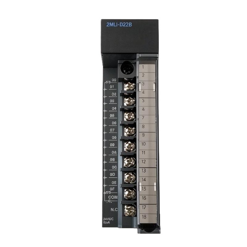
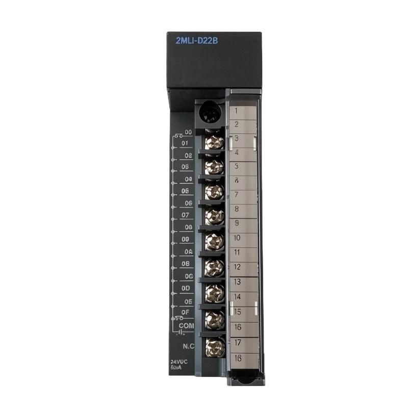
The Honeywell 2MLI-D22B is a 16-point DC 24V Digital Input Module belonging to the MasterLogic-200 PLC family. It is used to collect discrete signals from industrial field devices and transfer their operating status to the PLC CPU for control program execution.
Unlike the 2MLI-D22A, which supports both current source and sink input configurations, the 2MLI-D22B uses a current source input configuration. This distinction is important when selecting the module for an existing control cabinet because the field sensor wiring and signal output arrangement must match the input circuit requirements.
The module provides 16 input channels, allowing it to monitor several switching devices through a single I/O module. Typical connections include proximity sensors, limit switches, push buttons, and other compatible DC 24V field devices. In a packaging machine, for example, the module can collect signals from product detection sensors, guard switches, and cylinder position switches. The CPU then evaluates these signals to determine whether the next machine operation can proceed.
The 2MLI-D22B uses photocoupler isolation between the field input circuits and the internal PLC electronics. Each input channel has an LED status indicator, allowing maintenance personnel to check signal conditions directly at the module during commissioning or troubleshooting.
Input response time is another useful configuration feature. Both OFF-to-ON and ON-to-OFF transitions can be adjusted through CPU parameters, with seven selectable settings ranging from 1 ms to 100 ms. The default response time is 3 ms.
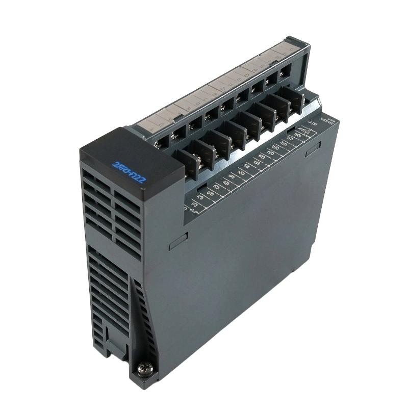
The module connects to the MasterLogic-200 system through an 18-point terminal block. Its 16-channel arrangement is suitable for machine control applications where multiple discrete signals need to be collected within a compact modular PLC configuration.
Technical Specifications
| Parameter | Specification |
|---|---|
| Manufacturer | Honeywell |
| Model | 2MLI-D22B |
| Product Type | Digital Input Module |
| Product Series | MasterLogic-200 |
| Input Type | DC Digital Input |
| Number of Input Points | 16 |
| Rated Input Voltage | 24 V DC |
| Rated Input Current | Approximately 4 mA |
| Input Configuration | Current Source Input |
| Operating Voltage Range | 20.4–28.8 V DC |
| Input Resistance | Approximately 5.6 kΩ |
| ON Voltage / Current | 19 V DC or higher / 3 mA or higher |
| OFF Voltage / Current | 11 V DC or lower / 1.7 mA or lower |
| Isolation Method | Photocoupler Isolation |
| Response Time | 1 / 3 / 5 / 10 / 20 / 70 / 100 ms |
| Default Response Time | 3 ms |
| Common Configuration | 16 Points / COM |
| Isolation Voltage | 560 V AC rms / 3 cycles |
| Isolation Resistance | 10 MΩ or higher |
| Current Consumption | 30 mA |
| Operation Indicator | Input ON LED |
| External Connection | 18-Point Terminal Block |
| Terminal Screw | M3 × 6 |
| Recommended Cable | Twisted Pair, 0.3–0.75 mm² |
| Recommended Crimp Terminal | R1.25-3 |
| Dimensions | 120 × 25 × 110 mm |
| Weight | 0.12 kg |
Product Features
1. Sixteen-Point DC 24V Input
The 2MLI-D22B provides 16 digital input channels for monitoring external switching signals. This allows multiple sensors and switches to be connected to one module, reducing the need to distribute individual signals across several smaller input modules.
2. Current Source Input Configuration
The module uses a current source input arrangement. This is an important selection consideration when connecting field sensors because the electrical output type and wiring polarity must match the module’s input requirements. It should not be treated as interchangeable with the source/sink configuration of the 2MLI-D22A without checking the wiring.
3. Photocoupler Isolation
Photocoupler isolation separates external input circuits from the internal PLC electronics. This electrical separation helps limit the transfer of disturbances from field wiring into the controller’s internal circuitry.
4. Adjustable Input Response Time
The module supports seven response-time settings: 1, 3, 5, 10, 20, 70, and 100 ms. Engineers can configure both OFF-to-ON and ON-to-OFF transitions through CPU parameters. The default setting is 3 ms.
5. Individual Input LED Indicators
Each input channel has an LED indicator that displays its ON status. During commissioning, technicians can activate individual field devices and observe the corresponding indicator to identify wiring or signal-related problems.
6. Shared Common Input Arrangement
The module uses a 16-point common configuration. This arrangement allows the 16 input channels to share the designated common connection, simplifying the field wiring layout.
7. Eighteen-Point Terminal Block Connection
External signals are connected through an 18-point terminal block with M3 × 6 screws. The terminal arrangement accommodates the 16 input channels together with the common and NC connections.
8. Standard Industrial 24V DC Compatibility
With a rated input voltage of 24V DC and an operating range of 20.4–28.8V DC, the module supports common industrial discrete signal circuits.
Working Principle
The 2MLI-D22B converts electrical switching signals from external DC 24V devices into digital information that can be processed by the MasterLogic-200 CPU.
When a connected field device changes state, its output circuit supplies the corresponding electrical signal to one of the module’s input terminals. The input circuit evaluates the voltage and current against the specified switching thresholds.
For an ON condition, the input voltage must reach at least 19V DC, with an input current of 3 mA or higher. For an OFF condition, the voltage must be 11V DC or lower, with an input current of 1.7 mA or lower.
The signal passes through the module’s photocoupler isolation stage before being recognized as a digital input state. The processed information is then transferred to the PLC CPU through the MasterLogic-200 backplane.
The CPU evaluates the input state against the programmed control conditions. For example, when a machine guard switch changes state, the CPU can use that information to determine whether a machine sequence should continue or stop according to the programmed interlock logic.
The response-time setting determines how quickly the module recognizes input transitions. Shorter settings are appropriate when the application requires faster signal recognition, while longer settings can be selected when the connected devices require additional filtering time.
Typical Signal Processing Path:
DC 24V Field Device → Input Terminal → Input Circuit → Photocoupler Isolation → MasterLogic-200 CPU → Control Logic
Example Machine Operation:
- A proximity sensor detects a product entering a conveyor section.
- The sensor changes its DC 24V output signal.
- The corresponding input channel on the 2MLI-D22B detects the electrical change.
- The module updates its digital input status.
- The MasterLogic-200 CPU evaluates the product detection signal and other operating conditions.
- The CPU executes the next programmed operation through the connected output modules.
Role in MasterLogic-200 Control Architecture
Within the MasterLogic-200 PLC system, the 2MLI-D22B serves as a 16-channel digital signal acquisition interface. It connects field-level switching devices to the central processing unit, allowing their operating conditions to become part of the PLC control program.
The module is particularly useful in installations where several groups of sensors need to be monitored. Instead of assigning each device to a separate module, engineers can collect up to 16 compatible DC 24V input signals through one 2MLI-D22B.
Its current source input configuration must be considered when planning the I/O architecture. The module is not electrically identical to the 2MLI-D22A, even though both belong to the same MasterLogic-200 digital input family.
In a typical control cabinet, the CPU executes the application program, the 2MLI-D22B acquires discrete field signals, and the corresponding output modules operate connected actuators and other equipment.
| Control System Component | Function |
|---|---|
| 2MLI-D22B | Acquires 16 DC 24V source-type input signals |
| 2MLI-CPUH | Executes PLC application programs |
| 2MLI-CPUS | Provides standard CPU processing |
| 2MLI-CPUU | Provides enhanced CPU processing |
| 2MLB-M04A | Main CPU base for modular installation |
| 2MLB-M06A | Main CPU base for modular installation |
| 2MLB-E04A | Provides additional I/O expansion |
| 2MLB-E08A | Provides additional I/O expansion |
| 2MLP-ACF1 | Supplies power to the PLC system |
| 2MLP-ACF2 | Supplies power to the PLC system |
| Digital Output Modules | Control discrete field equipment |
| Analog Input Modules | Acquire continuous process signals |
| SoftMaster | Supports PLC programming and configuration |
Industrial Applications
| Application | Digital Input Monitoring |
|---|---|
| Packaging Machinery | Monitors product detection sensors, machine guard switches, and operating conditions |
| Conveyor Systems | Collects workpiece detection and conveyor position signals |
| Assembly Lines | Monitors fixture positions, component presence, and machine interlocks |
| Material Handling | Acquires limit-switch and equipment status signals |
| Automotive Manufacturing | Monitors machine positions and discrete equipment feedback |
| Pneumatic Automation | Collects cylinder position and pressure-switch signals |
| Industrial Machine Tools | Monitors operating switches and machine status |
| Production Equipment | Coordinates sensor signals with programmed machine sequences |
| Pumping Systems | Monitors running feedback and discrete alarm conditions |
Installation and Maintenance
- Verify the Module Model: Confirm that the installed module is 2MLI-D22B and distinguish it from the source/sink input version 2MLI-D22A.
- Check Base Compatibility: Verify that the selected MasterLogic-200 base supports the intended module arrangement and that the rack configuration matches the PLC project.
- Confirm Input Wiring Type: The 2MLI-D22B uses a current source input configuration. Check the output type of each connected field device before wiring.
- Verify Supply Voltage: Confirm that the field signal voltage remains within the specified 20.4–28.8V DC operating range.
- Inspect Input Common Connections: Check the shared COM connection and ensure that all input channels follow the correct wiring arrangement.
- Use the Recommended Cable: Use twisted-pair cable with a conductor cross-section of 0.3–0.75 mm² and follow the specified external cable diameter requirements.
- Select Suitable Crimp Terminals: Use R1.25-3 crimp terminals. Do not use sleeve-attached compressed terminals for the specified connection arrangement.
- Check Terminal Block Connections: Inspect the 18-point terminal block and M3 × 6 screw connections. Ensure that conductors are properly secured and that no loose strands can cause short circuits.
- Configure Response Time: Set the OFF-to-ON and ON-to-OFF response times through CPU parameters according to the switching characteristics of the connected field devices.
- Monitor Input Indicators: Activate each field device and verify that the corresponding input ON LED responds correctly.
- Verify PLC Address Mapping: Check that the physical input channels match the addresses and variables used in the control program.
- Maintain Wiring Documentation: Record sensor assignments, terminal numbers, input addresses, and response-time settings to make future troubleshooting and replacement work easier.
Compatible System Components
| Component | Product Type | Application |
|---|---|---|
| 2MLI-CPUH | High Performance CPU Module | Executes PLC control logic |
| 2MLI-CPUS | Standard CPU Module | Provides standard PLC processing |
| 2MLI-CPUU | Enhanced CPU Module | Provides enhanced PLC processing |
| 2MLI-D21A | 8-Point Digital Input Module | Acquires DC 24V source/sink signals |
| 2MLI-D22A | 16-Point Digital Input Module | Acquires DC 24V source/sink signals |
| 2MLI-D24A | 32-Point Digital Input Module | Acquires DC 24V source/sink signals |
| 2MLI-D28A | 64-Point Digital Input Module | Acquires DC 24V source/sink signals |
| 2MLI-D24B | 32-Point Digital Input Module | Acquires DC 24V source-type signals |
| 2MLI-D28B | 64-Point Digital Input Module | Acquires DC 24V source-type signals |
| 2MLQ-RY1A | Relay Output Module | Controls relay-driven field loads |
| 2MLQ-TR2A | Transistor Output Module | Provides DC transistor output control |
| 2MLP-ACF1 | Power Supply Module | Supplies power to the PLC system |
| 2MLB-M06A | Main CPU Base | Houses the CPU and associated modules |
| 2MLB-E08A | Expansion I/O Base | Supports additional I/O modules |
| SoftMaster | PLC Programming Software | Configures and maintains the PLC application |
Recommended Related Models
| Model | Product Description |
|---|---|
| 2MLI-D22A | MasterLogic-200 16-Point DC 24V Source/Sink Digital Input Module |
| 2MLI-D24A | MasterLogic-200 32-Point DC 24V Source/Sink Digital Input Module |
| 2MLI-D28A | MasterLogic-200 64-Point DC 24V Source/Sink Digital Input Module |
| 2MLI-D24B | MasterLogic-200 32-Point DC 24V Source Input Module |
| 2MLI-D28B | MasterLogic-200 64-Point DC 24V Source Input Module |
| 2MLI-D21A | MasterLogic-200 8-Point DC 24V Digital Input Module |
Key Advantages
-
16 DC 24V digital input channels.
-
Current source input configuration.
-
Photocoupler isolation between field and internal circuits.
-
Seven selectable input response-time settings.
-
Default input response time of 3 ms.
-
Individual input ON LED indicators.
-
Shared 16-point common arrangement.
-
18-point terminal block connection.
-
Integration with the MasterLogic-200 PLC architecture.
-
Suitable for multi-sensor machine monitoring and discrete control applications.
Technical FAQs
What is the main difference between the 2MLI-D22B and 2MLI-D22A?
Both modules provide 16 DC 24V digital input channels, but their input configurations differ. The 2MLI-D22A supports current source and sink input arrangements, whereas the 2MLI-D22B uses a current source input configuration. Engineers should check the field device wiring and electrical output type before selecting a replacement.
Can the 2MLI-D22B monitor fast-changing sensor signals?
Yes. The module supports configurable response times of 1, 3, 5, 10, 20, 70, and 100 ms for both input transitions. The 1 ms setting can be selected when faster signal recognition is required, subject to the characteristics of the connected device and the application requirements.
How should the 16 input channels be wired?
The module uses a 16-point common arrangement and an 18-point terminal block. Each field signal must be connected to its corresponding input terminal, with the common connection wired according to the module’s current source input configuration. The specified twisted-pair cable and R1.25-3 crimp terminals should be used.
What should be checked if the module does not recognize a sensor signal?
Start by checking the sensor’s output type, wiring polarity, and supply voltage. Verify that the signal reaches the required ON threshold of 19V DC or higher and supplies at least 3 mA. Also inspect the common connection, terminal contacts, input LED indicator, and CPU input mapping. If the signal changes rapidly, review the configured response time as well.