

ProductPRODUCT
Featured products

Contact Us
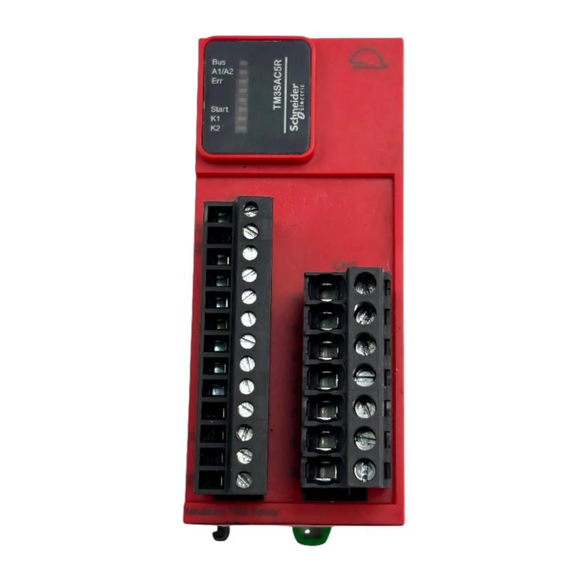
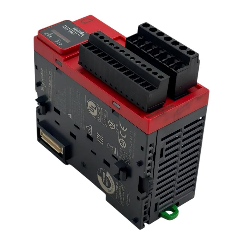
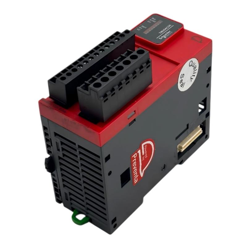
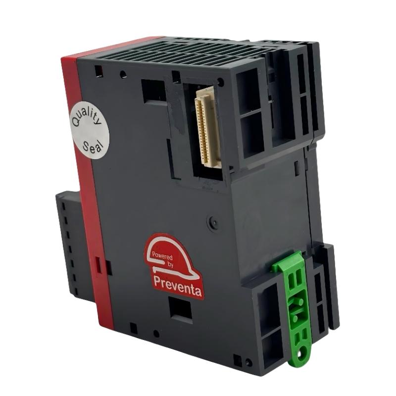
- Schneider
- TM3SAC5R
- Security Module
- France
- 94 x 43.7 x 73 mm
- 0.19 kg
- Xiamen, China
- New & In Stock
- T/T, PayPal, Western Union
- 1 Year
- 1-3 Working Days
- DHL, UPS, TNT, FedEx and EMS.
- 24-Hour Service
- COO
- 5
Our advantage

Global Logistics
We have a 10-year logistics and express cooperation agreement, so our products can be shipped to any place in the world.

Brand new and original
Our products are imported in bulk from the place of origin. Because of the cooperative relationship, our products are all original and 100% new.

24-hour service
We provide 7*24 hours service to our customers. We will be there whenever you need us.

Price advantage
All our products are priced very favorably because we have our own warehouse and supply.
| Company Information | |||
| [email protected] | |||
| Mobile | +8615980777398 | ||
| +8615980777398 | |||
| 15980777398 |
Product Overview
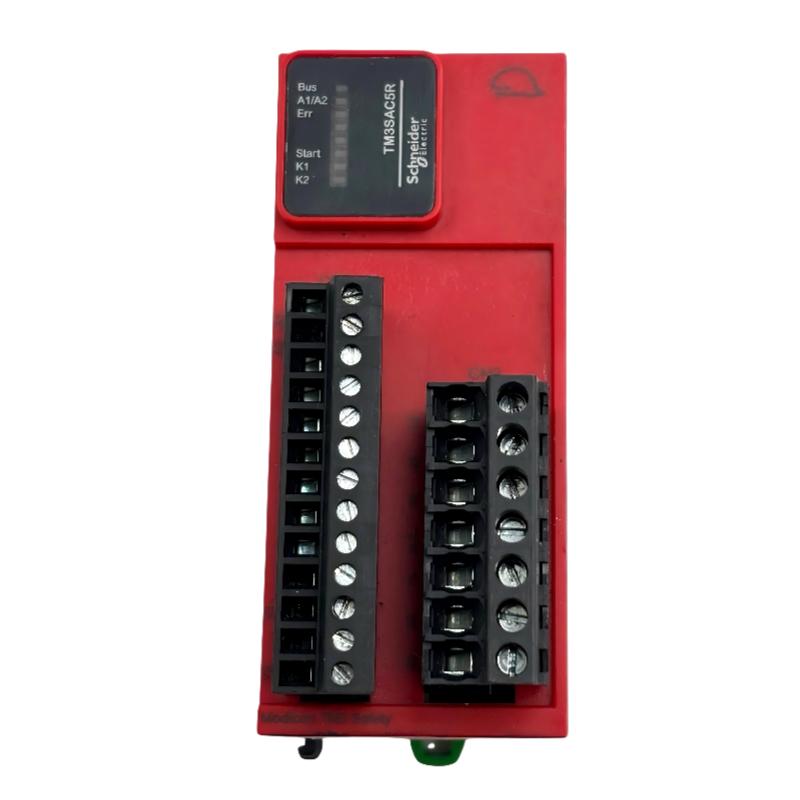
The Schneider Electric TM3SAC5R Safety Module is a functional safety component in the Modicon TM3 product family. It is designed to monitor emergency-stop circuits and protective guard switches in industrial machinery, helping implement safety-related control functions within an appropriately engineered automation system.
Manufactured by Schneider Electric, the TM3SAC5R is designed for use with compatible Modicon M2xx logic controllers and TM3 expansion modules. It provides dedicated safety monitoring functions that complement standard PLC control. Its purpose is to monitor safety-device signals and control safety-related relay outputs according to the configured circuit and operating conditions.
Unlike a standard digital input module, a safety module is intended for specific safety-related functions. It can monitor emergency-stop devices, selected guard-switch arrangements, and associated start or reset circuits. When the monitored circuit does not satisfy the required conditions, the module can switch its safety outputs to the appropriate state.
The TM3SAC5R uses a 24 V DC supply and removable screw terminal blocks. Its three normally open relay outputs provide switching interfaces for compatible external control circuits. The module supports safety applications that can achieve Category 3 / PL d and SIL CL 2, provided that the complete system design, wiring, component selection, and validation meet the applicable requirements.
The module has a compact design suitable for industrial control panels. Its supplied dimensions are 94 × 43.7 × 73 mm, and its weight is 0.19 kg. It can be mounted on a compatible DIN rail or installed using the manufacturer’s approved mounting method.
For machine builders and maintenance engineers, the TM3SAC5R can provide a practical way to incorporate safety monitoring into compatible Modicon control architectures. However, it must be selected and commissioned according to the machine’s risk assessment and the specific safety function required.
Technical Specifications
| Parameter | Specification |
|---|---|
| Brand | Schneider Electric |
| Product Model | TM3SAC5R |
| Product Family | Modicon TM3 Safety |
| Product Type | Functional Safety Module |
| Primary Function | Emergency-stop and protective-switch monitoring |
| Supply Voltage | 24 V DC |
| Input Configuration | Supports one-channel or two-channel safety circuits, subject to application requirements |
| Safety Outputs | 3 normally open relay outputs |
| Maximum Output Switching Rating | Up to 6 A per output path under specified conditions |
| Maximum Switching Voltage | 24 V DC / 230 V AC, subject to rated load and utilization category |
| Terminal Type | Removable screw terminal blocks |
| Safety Capability | Up to Category 3 / PL d and SIL CL 2 |
| Local Diagnostics | Green/red LED indicators |
| Mounting | Compatible DIN rail or approved panel mounting |
| Protection Rating | IP20 at terminals |
| Dimensions | 94 × 43.7 × 73 mm |
| Weight | 0.19 kg |
| Typical Application | Emergency-stop and machine-guard monitoring |
Important: Maximum switching values and achievable safety performance depend on the specified operating conditions and complete system design. Consult the manufacturer’s technical documentation before selecting wiring, fuses, or external switching devices.
Function and Working Principle
The TM3SAC5R monitors safety-related input circuits and controls its relay outputs according to the status of the connected devices and the selected wiring arrangement.
1. Emergency-Stop Circuit Monitoring
Emergency-stop devices allow operators to initiate a stop when a hazardous situation occurs. The TM3SAC5R can monitor compatible emergency-stop circuits and respond when the input conditions indicate that the circuit has been activated or interrupted.
When a valid emergency-stop signal is received, the module changes the state of its safety outputs. These outputs can be connected to suitable downstream control devices, such as contactors, to help remove hazardous machine energy through the designed safety circuit.
The module does not physically stop every type of machine by itself. The final stopping response depends on the downstream switching devices, machine design, and selected stopping category.
2. Protective Guard Monitoring
Industrial machinery often uses movable guards or access doors to prevent operators from reaching hazardous moving parts. The TM3SAC5R supports specified monitoring arrangements involving protective switches.
When a monitored guard opens or its input circuit becomes invalid, the module can switch its outputs to the configured safe state. The complete installation must use suitable safety-rated devices and wiring, and the safety function must be validated for the intended machine.
3. Safety Relay Output Control
The module provides three normally open relay outputs. These outputs can interface with external control circuits that execute the required machine response.
For example, a safety output may control an appropriately selected contactor circuit that removes power from a motor or another hazardous actuator. Output contact ratings, load characteristics, protective devices, and the downstream circuit architecture must all be considered.
The relay outputs should not be treated as a substitute for the entire safety system. Their performance depends on the connected components and the overall design.
4. Start and Reset Conditions
Depending on the wiring arrangement, the TM3SAC5R can be used with an appropriate start or reset circuit. Correct configuration helps ensure that machine operation follows the intended safety procedure after an emergency-stop event or guard opening.
Automatic and manual start arrangements have different implications for machine safety. The selected method must be consistent with the risk assessment and the manufacturer’s wiring instructions. Resetting a safety circuit should not automatically restart machinery where that restart could create a hazard.
5. Status Indication and Diagnostics
The module includes local LED indicators for status and diagnostic information. These indicators help commissioning and maintenance personnel assess the module’s operating state and identify certain wiring or operating issues.
LED indications should be interpreted using the manufacturer’s diagnostic table. They do not replace formal verification of the safety function or inspection of external devices.
Role in Industrial Control Systems
The TM3SAC5R provides a safety-monitoring function within a larger machine-control architecture. It can work alongside a compatible PLC, standard I/O modules, operator interfaces, contactors, emergency-stop devices, and protective switches.
Integration with Modicon Controllers
The TM3SAC5R is designed for compatible Modicon M2xx controller configurations and the Modicon TM3 expansion system. Its TM3 bus connections help maintain module-to-module connectivity within a supported arrangement.
The TM3 bus may carry information to the logic controller, but ordinary data transferred over this bus must not be used as the safety-related function itself. Safety functions must be implemented through the module’s intended safety circuitry and the appropriate external components.
Separation of Standard Control and Safety Functions
A standard PLC manages normal machine operation, including sequence logic, production timing, and process monitoring. The safety module handles the specific safety-monitoring functions for which it is designed.
For example, a PLC may control conveyor speed and coordinate product flow, while the safety module monitors the emergency-stop circuit. When an emergency stop is activated, the safety circuit must initiate the required response independently of ordinary process commands.
This separation helps ensure that a normal PLC command cannot override the intended safety response.
Interface with Contactors and Actuators
The module’s relay outputs can be connected to compatible downstream switching devices. Depending on the application, these may include motor contactors or other control components used to remove hazardous energy.
The complete circuit must be engineered to meet the required performance level. Where necessary, feedback monitoring and additional safety components should be included according to the design requirements.
Machine Safety Validation
The TM3SAC5R is only one element in the safety architecture. The machine manufacturer or system integrator remains responsible for evaluating the risks, selecting compatible components, implementing appropriate wiring, and validating the completed safety function.
The module’s published safety capability does not automatically establish that the complete machine meets a particular safety level.
Industrial Applications
The TM3SAC5R is suitable for specified machine-safety monitoring functions in industrial automation systems.
1. Emergency-Stop Systems
The module can monitor compatible emergency-stop pushbuttons installed at machine operating stations, production cells, or access points.
When an emergency-stop device is activated, the safety circuit can command the connected switching devices to initiate the required stop. The final response must match the machine’s risk assessment and stopping requirements.
2. Protective Door and Guard Monitoring
Machines with movable protective guards may require monitoring to prevent hazardous operation while an access door is open.
The TM3SAC5R supports specified protective-switch arrangements. The switch type, wiring, guard design, and restart behavior must be selected according to the applicable safety requirements.
3. Packaging Machinery
Packaging equipment may contain conveyors, cutting mechanisms, sealing units, and moving actuators. Safety monitoring can help coordinate emergency stops and guard interlocks with the machine’s overall control system.
The module may be considered for appropriate safety circuits in packaging equipment using compatible control hardware.
4. Material-Handling Equipment
Conveyors, transfer stations, and small automated handling machines often require emergency-stop devices at accessible locations. The TM3SAC5R can monitor compatible safety circuits and interface with downstream switching equipment.
The final design must account for the mechanical stopping distance, load behavior, and any additional safety functions required by the installation.
5. Assembly and Manufacturing Machines
Assembly equipment may use guarded work areas, pneumatic actuators, electric motors, and operator-access doors. Safety monitoring can help prevent hazardous movement when the monitored safety conditions are not satisfied.
The exact safety architecture depends on the machine’s hazards, required performance level, and selected protective devices.
6. Industrial Test and Auxiliary Equipment
Test fixtures and auxiliary production equipment may require emergency-stop or protective-switch monitoring. The TM3SAC5R can be considered where its supported safety functions and ratings match the application.
Engineers should verify that the module’s safety capability, output ratings, and wiring arrangements are appropriate before integrating it into the equipment.
Installation and System Integration
Correct installation is essential for reliable operation and the intended safety response.
1. Verify the Controller and Module Compatibility
Before installation, confirm that the controller supports the TM3 safety-module family and that the planned expansion arrangement is permitted by the manufacturer’s configuration rules.
Check the controller model, firmware requirements where applicable, expansion limits, module placement, and terminal configuration before commissioning.
2. Provide the Correct 24 V DC Supply
The TM3SAC5R uses a 24 V DC supply. The power source must meet the manufacturer’s requirements for protective extra-low voltage or safety extra-low voltage, as applicable.
Do not connect the module directly to mains voltage. Confirm supply polarity, grounding arrangements, current capacity, and the protection requirements for the power supply and output circuits.
3. Mount the Module Securely
The module measures 94 × 43.7 × 73 mm and weighs 0.19 kg. Confirm the dimensions and mounting clearance in the official drawing before arranging the panel layout.
Install the module on a compatible DIN rail or use an approved panel-mounting method. Ensure that adjacent modules are properly secured and that wiring can be installed without excessive strain on the terminals.
4. Wire Safety Inputs Correctly
Connect emergency-stop devices and protective switches according to the approved wiring diagram for the selected safety function. Verify whether the application requires one-channel or two-channel wiring and whether the chosen arrangement meets the machine’s risk assessment.
Do not assume that every two-channel arrangement provides the same diagnostic coverage or safety performance. Device selection, wiring, and the overall circuit architecture all affect the achievable result.
5. Connect Safety Outputs to Suitable Devices
The three normally open relay outputs can be used with compatible downstream control circuits. Verify the rated current and voltage, load type, utilization category, protective fuses, and any required contactor feedback arrangements.
Do not exceed the manufacturer’s specified output ratings. Inductive loads may require appropriate suppression measures, subject to the manufacturer’s instructions and the safety circuit design.
6. Configure Start and Reset Behavior
Set up the start or reset circuit according to the intended safety function. Verify that resetting an emergency-stop or guard circuit does not produce an unintended machine restart.
Where a manual reset is required, position the reset device so that the operator can perform the reset under the conditions specified by the risk assessment.
7. Test and Validate the Safety Function
After installation, test each emergency-stop device and protective switch. Verify the expected relay-output response, inspect wiring, confirm diagnostic indications, and check the behavior of downstream contactors or other switching devices.
The validation process should document the safety function, test results, and any required proof-test or inspection procedures. A successful power-up alone does not demonstrate that the complete safety system is compliant.
Compatible System Components
The TM3SAC5R is used as part of a wider safety and automation arrangement. Compatibility depends on the exact controller, safety devices, wiring, and downstream equipment.
| Component | Function | Integration Considerations |
|---|---|---|
| Compatible Modicon M2xx controller | Executes normal machine-control logic | Verify model and supported TM3 expansion configuration |
| Modicon TM3 expansion modules | Extend the controller’s I/O capabilities | Follow approved module arrangement and expansion limits |
| Emergency-stop pushbutton | Provides a manual emergency-stop input | Select suitable safety-rated hardware and correct wiring |
| Protective guard switch | Monitors access doors or movable guards | Verify switch type and required diagnostic coverage |
| 24 V DC PELV/SELV power supply | Supplies the safety module and associated circuits | Follow manufacturer voltage, isolation, and protection requirements |
| Motor contactor | Disconnects motor power when commanded by the safety circuit | Check coil requirements, contact ratings, and feedback-monitoring needs |
| Safety reset switch | Provides the intended reset command | Prevent unintended restart and follow the risk assessment |
| Terminal blocks and protective fuses | Support wiring and circuit protection | Use specified terminal types and fuse ratings |
| Control cabinet | Provides mechanical protection and organized wiring | Observe IP20 limitations and environmental requirements |
These components are examples of a potential system architecture and are not necessarily included with the TM3SAC5R.
Alternative Models and Replacement Considerations
When replacing a safety module, the replacement must support the same required safety functions and meet the system’s electrical and safety requirements. A device with a similar appearance or number of outputs is not necessarily equivalent.
| Alternative Model | General Consideration |
|---|---|
| Schneider Electric TM3SAC5RG | Related TM3 safety module with spring-type terminal connections; terminal style differs |
| Schneider Electric TM3SAF5R | Higher-capability safety module in the TM3 family; verify supported functions and required safety level |
| Schneider Electric TM3SAF5RG | Related safety-module variant with spring terminals; confirm wiring and configuration requirements |
| Schneider Electric TM3SAK6R / TM3SAK6RG | Different TM3 safety-module family variants; confirm exact functions, terminals, and safety characteristics |
| Schneider Electric Preventa safety relays | May suit certain standalone safety applications, but compatibility and system redesign must be evaluated |
Before selecting an alternative, compare:
- Supported safety functions and input arrangements.
- Achievable performance level and safety integrity level.
- Number and type of safety outputs.
- Supply voltage and power requirements.
- Terminal style and terminal assignments.
- Controller and expansion-system compatibility.
- Reset and start behavior.
- Diagnostic coverage and feedback-monitoring requirements.
- Mounting dimensions and cabinet clearance.
- Required validation and documentation.
A replacement safety device should be approved only after the complete safety function has been evaluated. Do not substitute a standard PLC I/O module for a safety module in a safety-related circuit.
Key Advantages
Dedicated Safety Monitoring
The TM3SAC5R is designed for specific emergency-stop and protective-switch monitoring functions rather than ordinary process I/O alone.
Compact Installation
Its compact 94 × 43.7 × 73 mm dimensions allow installation in suitably designed industrial control panels.
Removable Screw Terminals
The removable screw terminal blocks support organized wiring and can simplify certain installation and maintenance tasks.
Three Normally Open Relay Outputs
The module provides three relay outputs for integration with compatible external control circuits, subject to the rated switching conditions.
Local Status Indication
LED indicators help maintenance personnel inspect operating status and diagnose selected conditions during commissioning and troubleshooting.
Integration with Modicon TM3 Systems
The module is designed for compatible Modicon M2xx controller configurations and the TM3 expansion system, allowing safety monitoring to be incorporated into a broader machine-control architecture.
Defined Safety Capability
The module can support applications targeting Category 3 / PL d and SIL CL 2 when the complete system meets the applicable design, installation, and validation requirements.
Technical FAQs
1. What is the Schneider Electric TM3SAC5R?
The TM3SAC5R is a Modicon TM3 functional safety module used for specified emergency-stop and protective-switch monitoring applications.
2. What voltage does the TM3SAC5R require?
It uses a 24 V DC supply. The power source and associated wiring must comply with the manufacturer’s electrical and safety requirements.
3. How many safety outputs does it provide?
The module has three normally open relay outputs. Their permitted switching conditions depend on the specified voltage, current, load type, and utilization category.
4. What safety level can it achieve?
The module can support applications up to Category 3 / PL d and SIL CL 2. The achieved level depends on the complete safety system, including input devices, wiring, output devices, and validation.
5. Can it monitor emergency-stop pushbuttons?
Yes. Emergency-stop monitoring is one of its intended functions. The circuit must be wired according to the supported configuration and the machine’s risk assessment.
6. Can it monitor protective doors?
It can monitor specified protective-switch arrangements. Confirm the switch type, wiring method, and supported safety function before installation.
7. Can the TM3SAC5R replace a standard digital input module?
No. A standard digital input module should not be substituted for a safety module in a safety-related circuit unless a complete redesign establishes an appropriate certified safety architecture.
8. Does it connect to a Modicon PLC?
It is designed for compatible Modicon M2xx controllers and TM3 expansion configurations. Verify the controller model and expansion rules before integration.
9. What are its dimensions and weight?
The listed dimensions are 94 × 43.7 × 73 mm, and the weight is 0.19 kg.
10. What should be checked before purchasing a replacement?
Verify the complete model number, terminal type, supply voltage, safety functions, output ratings, condition, and compatibility with the existing controller and safety circuit. For critical machinery, replacement must be followed by the required safety validation.
Procurement and Maintenance Recommendations
When purchasing the Schneider Electric TM3SAC5R, confirm that the complete model number matches the equipment specification. Check whether the module is new, surplus, used, or refurbished, and request photographs of the nameplate and terminals when buying from an independent supplier.
For replacement projects, verify the supply voltage, screw terminal configuration, relay output requirements, and compatibility with the installed Modicon controller. If the original safety circuit has been modified, review the current wiring drawings rather than relying exclusively on historical documentation.
During maintenance, inspect terminal tightness, wiring condition, module mounting, and power-supply stability according to the manufacturer’s maintenance requirements. Test the emergency-stop and protective-guard functions at the intervals defined by the machine’s safety plan.
Never bypass a safety input or force an output merely to restore production without an approved risk assessment and procedure. Any change to the safety circuit should be documented and validated before the machine returns to normal operation.
Conclusion
The Schneider Electric TM3SAC5R Safety Module is a compact functional safety component for compatible Modicon TM3 automation systems. It supports specified emergency-stop and protective-switch monitoring functions, uses a 24 V DC supply, and provides three normally open relay outputs through removable screw terminal blocks.
With dimensions of 94 × 43.7 × 73 mm and a weight of 0.19 kg, the module is suited to appropriately designed industrial control panels. Its potential Category 3 / PL d and SIL CL 2 capability makes it relevant to machine-safety applications, provided the complete system is designed and validated to the required standards.
For purchasing, maintenance, and replacement, the key priorities are verifying the exact model, confirming controller and circuit compatibility, following the approved wiring instructions, and validating the full safety function before returning the machine to service.