

ProductPRODUCT
Featured products
Contact Us
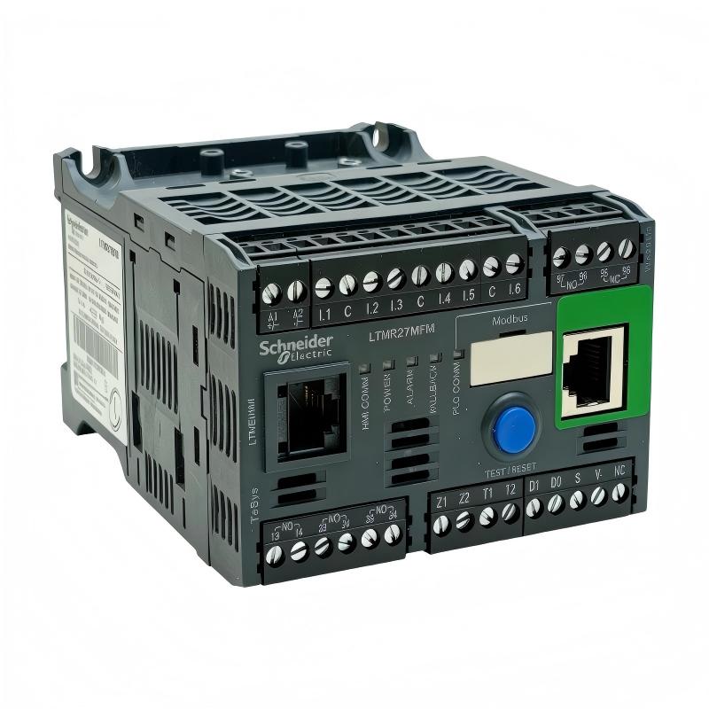
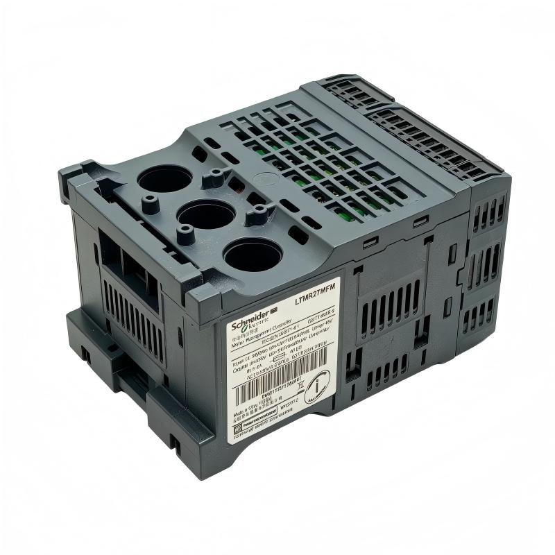
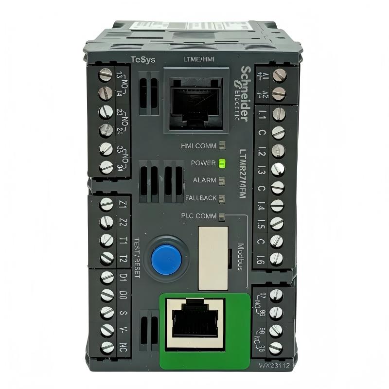
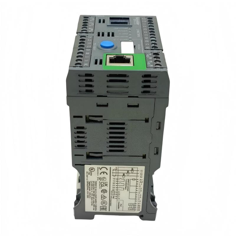
- Schneider
- LTMR27MFM
- Motor Controller
- France
- 91 x 61 x 122.5 mm
- 0.53 kg
- Xiamen, China
- New & In Stock
- T/T, PayPal, Western Union
- 1 Year
- 1-3 Working Days
- DHL, UPS, TNT, FedEx and EMS.
- 24-Hour Service
- COO
- 5
Our advantage

Global Logistics
We have a 10-year logistics and express cooperation agreement, so our products can be shipped to any place in the world.

Brand new and original
Our products are imported in bulk from the place of origin. Because of the cooperative relationship, our products are all original and 100% new.

24-hour service
We provide 7*24 hours service to our customers. We will be there whenever you need us.

Price advantage
All our products are priced very favorably because we have our own warehouse and supply.
| Company Information | |||
| [email protected] | |||
| Mobile | +8615980777398 | ||
| +8615980777398 | |||
| 15980777398 |
Product Overview
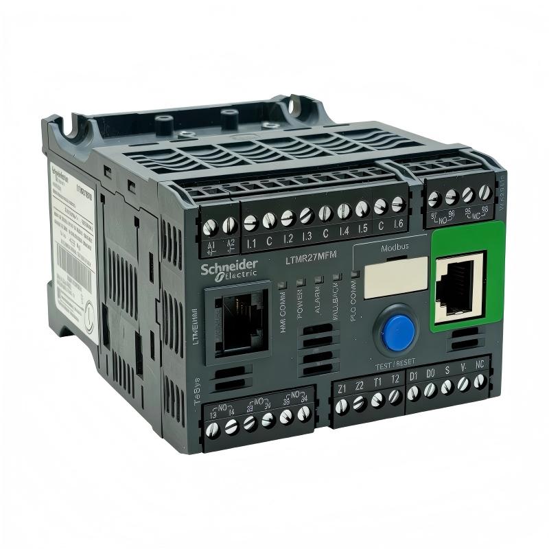
The Schneider Electric LTMR27MFM TeSys T Motor Controller is an intelligent motor management device designed for monitoring, controlling, and protecting three-phase AC motors in industrial automation systems. As part of the TeSys T motor management range, it combines current measurement, motor protection functions, programmable logic inputs and outputs, and Modbus communication in a compact controller.
Motor management is an important part of industrial reliability. Motors drive pumps, conveyors, compressors, fans, mixers, and many other machines. Electrical faults, overloads, phase problems, excessive starting time, and abnormal operating conditions can interrupt production and damage equipment. A motor controller helps detect relevant conditions and coordinate protective responses with the wider control system.
The LTMR27MFM supports a motor current measurement range of 1.35 to 27 A and uses a 100–240 V AC, 50/60 Hz control supply. It communicates through Modbus over a two-wire RS-485 interface and provides six logic inputs and three logic outputs for integration with suitable control circuits.
The controller can be integrated with a programmable logic controller (PLC), a human-machine interface (HMI), contactors, short-circuit protection devices, and compatible TeSys T system components. Depending on the system configuration, it can supply motor operating data, report faults, and support automated responses to abnormal conditions.
The LTMR27MFM is a motor management controller rather than a standalone variable frequency drive. It does not directly provide variable-frequency motor speed control. Instead, it monitors motor conditions and manages control and protection functions in conjunction with the appropriate switching and protection equipment.
Schneider Electric has announced the end of commercialization for this model as of September 30, 2026, with standard service scheduled to end on January 31, 2027. Buyers maintaining existing systems should verify availability and evaluate the manufacturer’s recommended replacement configuration before ordering.
Technical Specifications
| Parameter | Specification |
|---|---|
| Brand | Schneider Electric |
| Product Series | TeSys T |
| Model | LTMR27MFM |
| Product Type | Motor Management Controller |
| Primary Application | Industrial motor monitoring, control, and protection |
| Current Measurement Range | 1.35–27 A |
| Rated Control Supply Voltage | 100–240 V AC |
| Supply Frequency | 50/60 Hz |
| Supply Voltage Limits | 93.5–264 V AC |
| Communication Protocol | Modbus |
| Communication Interface | Two-wire RS-485 |
| Communication Connection | RJ45 and terminal-block options |
| Logic Inputs | 6 |
| Logic Outputs | 3 |
| Rated Insulation Voltage | 690 V |
| Short-Circuit Withstand Rating | Up to 100 kA under specified conditions |
| Dimensions | 91 × 61 × 122.5 mm |
| Weight | 0.53 kg |
| Product Lifecycle | End of commercialization announced |
| Standard Service End Date | January 31, 2027, according to manufacturer information |
Important: Electrical ratings and short-circuit withstand values must be interpreted according to the applicable manufacturer’s documentation and the selected protective devices. A controller’s withstand rating does not mean that it can interrupt a short circuit independently.
Function and Working Principle
The LTMR27MFM operates as the central monitoring and management unit in a compatible motor protection arrangement. It receives electrical measurements and external signals, evaluates them against configured parameters, and communicates status information or initiates protective control actions as appropriate.
1. Motor Current Measurement
The controller measures motor current across its supported range of 1.35 to 27 A. Current measurement is a fundamental element of motor protection because many abnormal operating conditions produce changes in the current drawn by the motor.
For example, an overloaded pump or conveyor may draw excessive current, while a mechanical obstruction can cause an abnormal starting or running condition. Monitoring current allows the controller to evaluate operating conditions against configured protection thresholds.
Correct setup requires the motor’s nameplate information, rated current, starting characteristics, and duty cycle to be taken into account. Protection settings should reflect the actual motor and application rather than relying on generic values.
2. Thermal Overload Protection
Motor windings can overheat when a motor operates under excessive load or experiences repeated high-current conditions. The LTMR27MFM provides thermal overload protection intended to help prevent motor damage.
The controller evaluates motor operating conditions according to its configured protection model and parameters. When a trip condition is detected, the controller can report the fault and coordinate the appropriate shutdown response through the connected control circuit.
Thermal overload protection should be configured to suit the motor’s rated current, starting time, and operating duty. It complements rather than replaces correctly selected short-circuit protection.
3. Phase and Current Imbalance Monitoring
Three-phase motors depend on a suitable supply across all phases. Phase loss, imbalance, and abnormal current conditions can affect motor torque and temperature, potentially reducing equipment reliability.
The LTMR27MFM includes protection functions for conditions such as phase failure and phase unbalance. Monitoring these conditions helps maintenance personnel identify electrical supply problems before they result in prolonged downtime or equipment damage.
The response to a detected fault depends on the configured thresholds, application settings, and connected switching equipment.
4. Locked-Rotor and Starting-Time Monitoring
A motor may fail to accelerate because of a mechanical obstruction, excessive load, or an electrical problem. A locked rotor or excessively long starting period can expose the motor to damaging current and temperature conditions.
The controller supports locked-rotor and starting-related protection functions. By evaluating motor conditions during startup and operation, it can help identify when a motor fails to start within its permitted operating parameters.
Engineers should configure the starting time and relevant protection settings according to the motor and driven equipment. Settings that are too restrictive may cause nuisance trips, while settings that are too permissive may provide insufficient protection.
5. Logic Inputs and Outputs
The LTMR27MFM has six logic inputs and three logic outputs. These interfaces allow it to receive external signals and exchange control or status signals with other equipment.
Depending on the application, input signals may be used for operating commands, interlocks, or external status conditions. Outputs can be incorporated into suitable control circuits to signal operating states or support fault-management actions.
The electrical characteristics and intended functions of each terminal should be checked against the manufacturer’s wiring documentation before installation.
6. Modbus Communication
The controller supports Modbus communication over a two-wire RS-485 interface. This enables data exchange with compatible PLCs, supervisory systems, and other industrial devices.
Depending on the supported register map and configuration, the control system can access relevant operating measurements, status information, alarms, and diagnostic data. Communication settings such as device address, baud rate, and wiring topology must be configured correctly.
Modbus communication improves visibility into motor operating conditions, but it does not replace hardwired protection or safety circuits where those are required by the system design.
Role in Industrial Control Systems
The LTMR27MFM can serve as a motor management layer within a motor control center (MCC) or an automated production system. It monitors motor-related conditions and coordinates with other electrical and control components to support reliable operation.
PLC Integration
A PLC typically manages the overall production sequence, including sensor processing, interlocks, timing, and coordination among multiple machines. The LTMR27MFM complements the PLC by providing dedicated motor monitoring and protection functions.
Through Modbus, a compatible PLC can collect available motor data and status information. The PLC may use this information to display alarms, prevent a process from starting under unsuitable conditions, or coordinate a controlled response to a motor fault.
The actual functions available to the PLC depend on the device’s communication register map, configuration, and control-system programming.
HMI and Operator Monitoring
An HMI can display motor current, operating status, fault information, and other available data supplied by the controller or PLC. Operators can use this information to identify abnormal conditions and communicate maintenance requirements.
For example, repeated overload trips on a conveyor motor may indicate excessive material accumulation, mechanical friction, or an incorrectly selected motor. Fault records and operating information can help maintenance teams investigate the underlying cause.
The HMI is normally part of the broader control system and should be configured to display information relevant to the equipment being monitored.
Motor Control Circuit Coordination
The LTMR27MFM is commonly used with suitable contactors and short-circuit protection devices. The controller monitors the motor and supports control and protection functions, while the contactor and protective devices perform their respective switching and fault-protection roles.
Correct coordination is essential. The contactor, short-circuit protective device, motor, and controller must be selected as a compatible arrangement for the installation’s electrical conditions.
Motor Control Center Applications
In an MCC, multiple motor feeders are installed in a common electrical assembly. A motor management controller such as the LTMR27MFM can provide consistent monitoring and protection for an individual motor feeder within the limits of its current range.
This architecture helps maintenance teams manage multiple motors while centralizing operating information through the control network.
Industrial Applications
The LTMR27MFM can be applied to motor-driven equipment whose electrical and control requirements are compatible with its specifications.
1. Pumping Systems
Industrial pumps are used in water treatment, cooling circuits, process plants, and fluid-transfer systems. Motor overload, phase problems, and abnormal starting conditions can interrupt flow and affect downstream equipment.
The LTMR27MFM can monitor compatible pump motor conditions and communicate relevant status information to a PLC or supervisory system. Where appropriate, this information can help trigger alarms or initiate a coordinated shutdown.
The controller does not itself regulate pump speed. Variable-speed operation requires a suitable drive or another appropriate speed-control arrangement.
2. Conveyor Systems
Conveyors are widely used in manufacturing, packaging, warehousing, and material handling. Mechanical obstruction, excessive load, and motor-starting problems can interrupt production.
Motor current monitoring and protective functions can help detect abnormal operating conditions. Modbus communication also allows the control system to integrate motor status into conveyor sequencing and fault diagnostics.
The current measurement range must be appropriate for the connected motor and its operating duty.
3. Fans and Ventilation Equipment
Industrial fans support cooling, ventilation, air handling, and process exhaust. A motor fault can reduce airflow or interrupt a production process.
The LTMR27MFM can support monitoring and protection of compatible fan motors. Integrating the controller with a PLC allows motor faults to be communicated to operators and incorporated into equipment interlocks.
Where variable airflow is required, the system may also need a compatible variable frequency drive.
4. Compressors and Auxiliary Machinery
Motors used in auxiliary compressors and industrial machinery may operate under changing mechanical loads. Abnormal loading or repeated difficult starts can increase motor heating and maintenance requirements.
A suitable motor management arrangement can monitor operating conditions and coordinate protection responses. The controller’s current range, motor-starting characteristics, and protection requirements must be evaluated before selecting it for compressor service.
5. Water and Wastewater Treatment
Water and wastewater facilities use motors in pumps, mixers, aeration equipment, and other process machinery. Motor failure can affect flow, treatment performance, and plant availability.
The LTMR27MFM can be integrated into a PLC-based monitoring system to provide relevant motor data and fault information. Its suitability depends on the motor current, electrical installation, control architecture, and environmental conditions.
6. Manufacturing and Process Plants
Production lines frequently contain many motors that operate in coordinated sequences. A motor management controller can provide local monitoring and protection while the PLC supervises the overall process.
By consolidating motor status and diagnostic information, the system can help maintenance teams identify recurring faults and plan corrective work.
Installation and System Integration
Correct installation is essential for accurate measurement, reliable communication, and effective motor protection.
1. Verify Motor Current Compatibility
The LTMR27MFM supports a current measurement range of 1.35 to 27 A. Confirm that the connected motor’s rated current and operating characteristics fall within the permitted range.
The motor’s nameplate current, starting time, duty cycle, and expected loading should be reviewed before configuring protection settings. If the motor falls outside the controller’s range, select an appropriate alternative rather than relying on unsupported settings.
2. Confirm the Control Supply
The controller uses a nominal 100–240 V AC, 50/60 Hz control supply, with documented supply voltage limits of 93.5–264 V AC.
Verify the actual control voltage before wiring the device. Do not assume that a 24 V DC controller variant is interchangeable with this AC-powered model.
3. Install in a Suitable Enclosure
The supplied dimensions are 91 × 61 × 122.5 mm, and the listed weight is 0.53 kg. Confirm mounting arrangements and clearance requirements using the manufacturer’s installation documentation.
Install the controller in a suitable electrical enclosure with appropriate protection against dust, moisture, vibration, and other environmental conditions. Provide adequate space for wiring, terminal access, and maintenance.
4. Configure Protection Parameters
Set the motor-related parameters according to the motor nameplate and application requirements. These may include rated current, overload settings, starting-time limits, and applicable phase or fault-protection thresholds.
Incorrect settings can result in unnecessary trips or insufficient protection. Commissioning should include verification of the configured values and, where practical, controlled testing of the intended fault response.
5. Connect Logic Inputs and Outputs
The LTMR27MFM provides six logic inputs and three logic outputs. Check the terminal assignment, input electrical characteristics, output contact ratings, and required external circuit protection before connecting control wiring.
Document the function of each input and output so that maintenance personnel can understand how the controller interacts with the PLC, contactor, and other devices.
6. Configure Modbus Communication
For Modbus integration, configure the device address, baud rate, and other communication parameters according to the control-system design. The documented interface supports a two-wire RS-485 connection through the available connection options.
Use suitable communication cable and follow the recommended wiring topology, grounding, shielding, and termination practices. Incorrect addressing, inconsistent serial settings, or wiring faults can cause communication failures.
After installation, verify that the PLC can read the expected data and correctly identify communication loss or device faults.
7. Commission the Motor Protection Arrangement
Before returning equipment to service, verify the motor connections, protective devices, contactor operation, control wiring, and communication settings.
Test normal starting and stopping, confirm that operating data is plausible, and validate the intended fault-handling sequence. Record the final settings and wiring details for future maintenance.
Compatible System Components
The LTMR27MFM operates as part of a complete motor management arrangement. Component selection should be based on the motor, electrical installation, protection coordination, and control-system requirements.
| Component | Function | Integration Considerations |
|---|---|---|
| Three-phase AC motor | Converts electrical energy into mechanical motion | Confirm rated current, starting characteristics, and duty |
| Contactor | Switches the motor power circuit | Select an appropriate motor-duty contactor and control arrangement |
| Short-circuit protective device | Provides short-circuit protection | Coordinate ratings and performance with the complete assembly |
| PLC | Supervises machine logic and process sequencing | Verify Modbus compatibility and required data points |
| HMI | Displays motor status and alarms | Configure suitable tags and diagnostic displays |
| Modbus RS-485 cable | Carries serial communication | Use suitable cable, topology, and termination practices |
| Control power supply | Supplies the controller’s control circuit | This model requires the specified 100–240 V AC supply |
| Motor temperature sensor or related input device | Supplies additional monitoring information where supported | Verify the supported sensor type and system configuration |
| TeSys T expansion module | Extends supported monitoring or measurement capabilities | Confirm the exact module and compatibility requirements |
| Electrical enclosure | Protects installed components | Provide suitable environmental protection and wiring access |
The exact components required depend on the application. The controller should not be treated as a replacement for a contactor, short-circuit protective device, or other equipment required for a complete motor feeder.
Alternative Models and Replacement Considerations
Schneider Electric has announced the end of commercialization for the LTMR27MFM effective September 30, 2026. The manufacturer lists replacement configurations based on a TeSys Tera main unit and a matching current sensor module.
| Alternative | Description | Important Considerations |
|---|---|---|
| LTMTMFM | TeSys Tera Modbus motor management main unit | Verify the required control supply, I/O, communication settings, and system architecture |
| LTMTCTV3UT | TeSys Tera current sensor module, 0.3–3 A range | Suitable only where the motor current and application requirements match |
| LTMTCTV25UT | TeSys Tera current sensor module, 2.5–25 A range | Check the motor’s operating current and required protection coverage |
| LTMTCTV100UT | TeSys Tera current sensor module, 10–100 A range | Intended for a different current range; not a direct substitute for every LTMR27MFM installation |
| LTMR27MFM | Original TeSys T motor controller | May be considered for existing-system maintenance if available and compatible with the original design |
The manufacturer’s replacement recommendations involve a main unit and a selected current sensor module. Buyers should confirm the correct combination rather than ordering only one component and assuming it will replace the original controller.
Before upgrading, compare the original and replacement systems for:
- Motor current range and overload protection.
- Control supply voltage.
- Communication protocol and data mapping.
- Logic input and output availability.
- Contactor control and fault-management logic.
- Motor feeder wiring and short-circuit protection.
- Mounting dimensions and panel space.
- PLC program changes and commissioning requirements.
A replacement may require changes to wiring, communication settings, PLC logic, and commissioning procedures. For critical applications, plan the migration carefully and verify that the complete replacement arrangement meets the original system’s protection requirements.
Key Advantages
Integrated Motor Management
The LTMR27MFM combines motor current monitoring, protection functions, logic interfaces, and communication in one compact controller.
Broad Current Measurement Range
Its 1.35–27 A range supports a variety of compatible low-current industrial motor applications, subject to the motor’s actual operating requirements.
Modbus Communication
The RS-485 Modbus interface supports integration with compatible PLCs and supervisory systems, helping centralize motor status and diagnostic information.
Multiple Logic Inputs and Outputs
Six logic inputs and three logic outputs allow the controller to interact with external control signals and suitable motor-management circuits.
Comprehensive Protection Functions
The device supports protection functions addressing conditions such as overload, phase failure, phase unbalance, locked rotor, and thermal overload.
Compact Installation Footprint
With dimensions of 91 × 61 × 122.5 mm and a listed weight of 0.53 kg, the controller can fit into suitable motor-control panels with appropriate wiring and environmental clearances.
Support for Diagnostic Maintenance
Available motor data, fault information, and event-related diagnostics can help maintenance personnel investigate abnormal operating conditions and improve troubleshooting efficiency.
Technical FAQs
1. What is the Schneider Electric LTMR27MFM?
The LTMR27MFM is a TeSys T motor management controller designed for monitoring, controlling, and protecting compatible industrial motors. It supports Modbus communication and provides six logic inputs and three logic outputs.
2. What is its motor current measurement range?
The supported current measurement range is 1.35 to 27 A. The connected motor’s current and starting characteristics should be checked before selecting and configuring the controller.
3. What control supply does it require?
The LTMR27MFM uses a nominal 100–240 V AC, 50/60 Hz control supply. Its documented supply voltage limits are 93.5–264 V AC.
4. Does it support Modbus communication?
Yes. It supports Modbus over a two-wire RS-485 interface. The communication address and serial settings must be configured to match the connected PLC or supervisory system.
5. Does it function as a variable frequency drive?
No. It is a motor management controller, not a variable frequency drive. It monitors motor conditions and provides protection and control functions in a suitable motor-control arrangement. Variable-speed operation requires a compatible drive or another appropriate speed-control device.
6. Can it be used with a PLC?
Yes. A compatible PLC can communicate with the controller through Modbus and use available motor data and status information in the wider automation sequence. The actual functions depend on the communication configuration and application programming.
7. What motor protection functions does it provide?
The device supports functions including thermal overload, overload, phase failure, phase unbalance, locked rotor, and related monitoring functions. Correct configuration and suitable external protective devices are essential.
8. What are its dimensions and weight?
The listed dimensions are 91 × 61 × 122.5 mm, and the listed weight is 0.53 kg.
9. Is the LTMR27MFM discontinued?
Schneider Electric announced that commercialization would end on September 30, 2026, and standard service would end on January 31, 2027. Availability and service options should be confirmed with the manufacturer or an authorized distributor.
10. What is the recommended replacement?
The manufacturer’s recommended replacement approach uses a TeSys Tera Modbus main unit, LTMTMFM, together with a compatible current sensor module selected according to the motor’s current range. The complete combination must be checked against the existing installation.
Procurement and Maintenance Recommendations
When purchasing the Schneider Electric LTMR27MFM, verify the full model number, current range, control supply, communication interface, and physical condition. For an existing installation, compare the catalog number with the label on the installed controller before ordering a replacement.
Because the end of commercialization has been announced, buyers should confirm stock availability, warranty terms, and service support. For used or refurbished units, request clear photographs of the label and terminals, details of the unit’s condition, and available functional test information.
For new installations or replacement projects, verify that the controller is compatible with the motor, contactor, short-circuit protective device, PLC, and required control architecture. The manufacturer’s replacement arrangement may involve multiple components, so confirm the complete bill of materials before procurement.
During maintenance, inspect terminal connections, wiring, enclosure condition, and communication reliability according to the applicable maintenance procedures. Review fault records and operating information when investigating repeated trips. Always isolate the equipment and follow the required electrical safety procedures before working on the motor control circuit.
When migrating to a newer motor management platform, document the original protection settings, PLC data mapping, input and output functions, and fault-handling sequence. Test the new arrangement thoroughly before returning critical machinery to normal operation.
Conclusion
The Schneider Electric LTMR27MFM TeSys T Motor Controller is an intelligent motor management device designed for industrial motor monitoring, control, and protection. It supports a 1.35–27 A current measurement range, a 100–240 V AC control supply, Modbus RS-485 communication, six logic inputs, and three logic outputs.
Its monitoring and protection functions make it suitable for compatible motor feeders used in pumping, conveying, ventilation, manufacturing, and other industrial applications. Since Schneider Electric has announced the end of commercialization, accurate identification and lifecycle planning are important for maintenance and procurement.
For replacement projects, verify the complete electrical and communication requirements and evaluate the manufacturer’s recommended TeSys Tera main unit and current sensor combination. Careful configuration, installation, and commissioning help ensure that the motor management system operates reliably within the intended industrial control architecture.