

ProductPRODUCT
Featured products
Contact Us
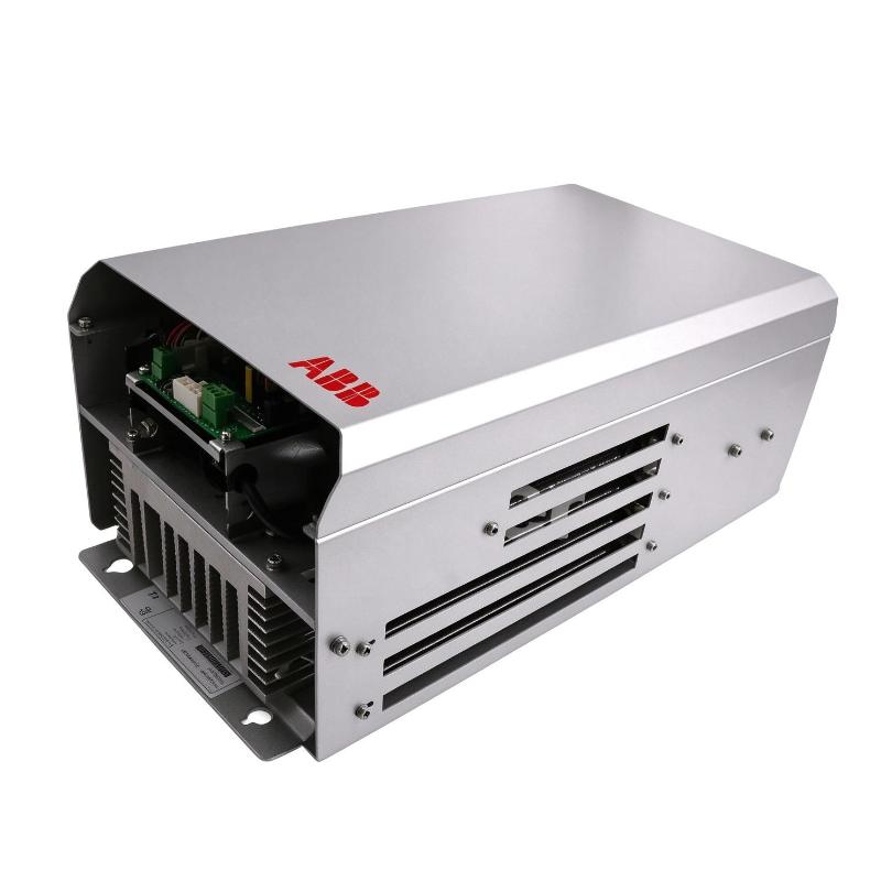
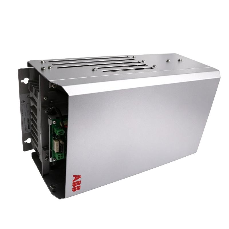
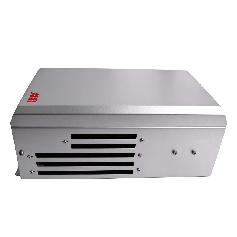
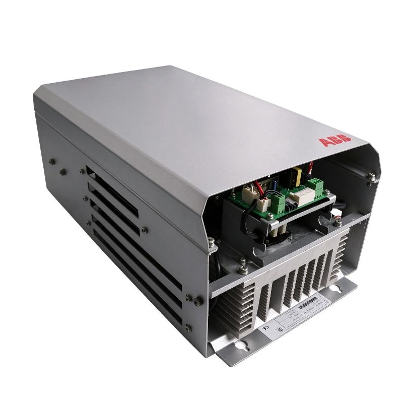
- ABB
- NBRA-669C 3ABD58984124
- Brake Chopper
- Sweden (SE)
- 583 x 240 x 337 mm
- 27.7 kg
- Xiamen, China
- New & In Stock
- T/T, PayPal, Western Union
- 1 Year
- 1-3 Working Days
- DHL, UPS, TNT, FedEx and EMS.
- 24-Hour Service
- COO
- 8
Our advantage

Global Logistics
We have a 10-year logistics and express cooperation agreement, so our products can be shipped to any place in the world.

Brand new and original
Our products are imported in bulk from the place of origin. Because of the cooperative relationship, our products are all original and 100% new.

24-hour service
We provide 7*24 hours service to our customers. We will be there whenever you need us.

Price advantage
All our products are priced very favorably because we have our own warehouse and supply.
| Company Information | |||
| [email protected] | |||
| Mobile | +8615980777398 | ||
| +8615980777398 | |||
| 15980777398 |
Product Overview
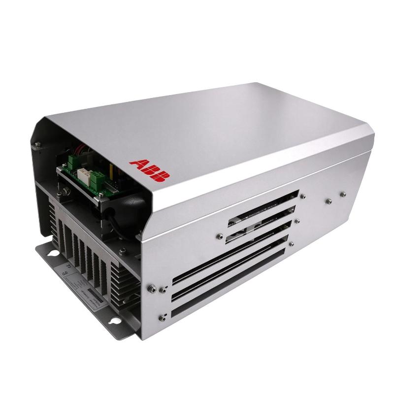
The ABB NBRA-669C 3ABD58984124 Braking Chopper is an external braking chopper module designed for use with compatible ABB industrial drive systems. It manages regenerative energy generated when a motor decelerates or drives an overhauling load. By controlling the connection between the drive’s DC bus and an external braking resistor, the module helps dissipate excess electrical energy and supports controlled braking operation.
In industrial applications, motors do not always consume energy. During deceleration, lowering operations, and certain high-inertia processes, a motor can operate as a generator and return energy to the drive’s DC bus. If that energy cannot be returned to the supply or otherwise managed, the DC bus voltage may rise beyond the permitted operating range. A braking chopper helps address this condition by switching an external braking resistor into the circuit when required.
The NBRA-669C belongs to ABB’s NBRA braking-chopper family and is associated with high-power industrial drive applications. Product documentation identifies the NBRA-669C for compatible 690 V drive configurations, including relevant R8/R9 frame applications. Exact compatibility depends on the drive model, DC bus voltage, braking duty, resistor specification, and installation design.
This component is not a standalone braking resistor and is not a complete frequency converter. It is part of a braking system that normally includes a compatible drive, a braking chopper, an appropriately rated resistor, and suitable electrical protection.
For maintenance and procurement, the complete product designation NBRA-669C and ordering number 3ABD58984124 should be checked before replacement. Similar braking modules may have different voltage classes, power capabilities, connections, or intended drive configurations.
Technical Specifications
| Parameter | Specification |
|---|---|
| Brand | ABB |
| Product Model | NBRA-669C |
| Ordering Number | 3ABD58984124 |
| Product Type | External Braking Chopper / Brake Module |
| Product Family | ABB NBRA Braking Choppers |
| Application | Industrial drive braking and regenerative-energy dissipation |
| Compatible Drive Context | Specified ABB high-voltage drive configurations |
| Published Application Reference | 690 V, compatible R8/R9 drive applications |
| Braking Resistor | External resistor required |
| Main Function | Controls energy dissipation through an external braking resistor |
| Installation Type | External drive accessory |
| Enclosure Protection | Verify the applicable installation documentation; the module is generally intended for installation within a suitable protective enclosure |
| Dimensions Provided | 583 × 240 × 337 mm |
| Weight Provided | 27.7 kg |
| Typical Use | High-inertia motors, controlled deceleration, and regenerative-load applications |
The dimensions and weight above are the supplied listing values. Published references for this model family show dimensions of approximately 583.5 × 334 × 240 mm and weights around 24–26 kg, depending on the source and configuration. Confirm the exact unit and manufacturer’s dimensional drawing before publishing final logistics data.
Function and Working Principle
The ABB NBRA-669C operates as a switching element in a drive braking circuit. Its purpose is to control the flow of regenerative energy from the DC bus to an external braking resistor.
1. Managing Regenerative Energy
During normal motoring operation, the drive supplies electrical energy to the motor. When the motor slows down or a load drives the motor mechanically, the motor may return energy to the drive.
This regenerative energy can increase the voltage of the drive’s DC bus. If the voltage rises beyond the permitted level, the drive may trigger an overvoltage fault or interrupt operation.
The NBRA-669C helps manage this energy by controlling when the external braking resistor is connected to the DC bus.
2. Switching the Braking Resistor
A braking chopper uses power-switching electronics to control current through the braking resistor. When braking conditions require energy dissipation, the chopper switches the resistor into the circuit. The resistor converts the electrical energy into heat.
The chopper’s switching operation is coordinated with the DC bus voltage and the braking system’s design. The external resistor must be selected to match the required braking power, resistance, energy capacity, and duty cycle.
The resistor is a separate component and should not be assumed to be included with the NBRA-669C.
3. Supporting Controlled Deceleration
In applications with high rotational inertia, rapid deceleration can generate substantial regenerative energy. Without an appropriate energy-management arrangement, the drive may be unable to decelerate the motor at the required rate.
A correctly engineered braking chopper and resistor system can support faster or more frequent deceleration within the limits of the drive and braking components.
The achievable stopping time depends on motor characteristics, load inertia, the braking resistor, the chopper, and the drive’s configured limits. The module alone does not determine the complete braking performance.
4. Protecting Drive Operation
By helping control DC bus voltage during regenerative operation, the braking chopper can reduce the likelihood of overvoltage interruptions caused by excessive regenerative energy.
However, it is not a substitute for all drive protection functions. Correct electrical protection, resistor thermal management, grounding, and drive configuration remain essential.
5. Converting Energy into Heat
A braking resistor dissipates the energy handled by the chopper as heat. This creates thermal requirements that must be considered during system design.
The resistor should be mounted in a location with adequate heat dissipation and appropriate separation from temperature-sensitive equipment. Its resistance, power rating, pulse-energy capability, and duty cycle must follow the drive manufacturer’s specifications.
Role in Industrial Drive Systems
The NBRA-669C is part of the braking subsystem in a larger motor-drive installation. It works with the drive’s DC bus and an external braking resistor to manage energy during deceleration or regenerative operation.
Integration with ABB Frequency Converters
The module is intended for compatible ABB drive configurations. Before installation, engineers should confirm the supported drive family, voltage class, frame size, DC bus connections, and braking requirements.
The NBRA-669C should not be assumed to work with every ABB frequency converter. Compatibility must be established from the relevant drive and braking-chopper documentation.
Coordination with Motor Control
A drive controls motor speed, torque, acceleration, and deceleration. The braking chopper complements these functions when regenerative energy needs to be dissipated through a resistor.
For example, a drive may be commanded to stop a motor quickly. As the motor decelerates, the drive manages the motor’s electrical output while the chopper controls energy dissipation through the resistor, subject to the system’s ratings.
Support for High-Inertia Loads
Large fans, centrifuges, material-handling equipment, and other rotating machinery may store considerable kinetic energy. During stopping, this energy must be managed safely.
A properly sized braking system helps the drive handle these operating conditions while reducing unnecessary interruptions caused by DC bus overvoltage.
System-Level Protection
The braking chopper is only one part of the complete electrical design. The drive, resistor, cables, protective devices, enclosure, and cooling arrangements must work together.
For safety-critical machinery, the braking arrangement must also be assessed against the machine’s stopping requirements and applicable safety standards.
Industrial Applications
The ABB NBRA-669C is intended for industrial drive applications where regenerative energy and braking performance require careful management. Its use should be determined by the drive configuration and calculated braking requirements.
1. High-Inertia Industrial Machinery
Rotating machinery can continue moving after the drive reduces motor power. A braking chopper and resistor can help dissipate the energy generated during deceleration.
Examples include large rotating equipment and process machines where stopping time and drive overvoltage need to be controlled.
2. Cranes and Material Handling
Certain lifting and lowering applications can cause a motor to regenerate energy, particularly when a load drives the motor. A suitable braking system helps manage this energy.
The complete crane or hoist design must separately address mechanical brakes, load-holding requirements, control-system safety, and the applicable lifting-equipment standards. An electrical braking chopper does not replace a mechanical holding brake.
3. Industrial Conveying Systems
Long or high-inertia conveyors may require controlled deceleration, especially when carrying substantial material loads. The braking arrangement can help manage regenerative energy during stopping.
The braking resistor and chopper must be selected according to the conveyor’s inertia, stopping frequency, load conditions, and required deceleration profile.
4. Fans and Centrifugal Equipment
Large fans and other rotating equipment can store significant kinetic energy. If the application requires relatively rapid deceleration, the drive may need a braking-energy dissipation solution.
Engineers should assess whether the operating cycle requires a braking chopper, whether natural coast-down is acceptable, and how much braking energy must be dissipated.
5. Industrial Process Lines
Manufacturing and process equipment may require controlled stopping to protect machinery, maintain product quality, or coordinate operations with other equipment.
The NBRA-669C may form part of the braking solution when used with a compatible ABB drive and correctly specified external resistor.
Installation and System Integration
Correct installation is essential for safe operation, thermal performance, and reliable braking.
1. Confirm Drive Compatibility
Before installation, identify the exact ABB drive model and verify that it supports the NBRA-669C. Confirm the DC bus voltage, frame size, terminal arrangement, and applicable braking-chopper documentation.
Do not select a braking chopper based only on physical dimensions or a general drive power rating. Different drive configurations can require different braking components.
2. Verify the External Braking Resistor
The NBRA-669C requires a suitable external braking resistor. Its resistance value and power rating must comply with the manufacturer’s recommendations for the connected drive and the intended braking duty.
The engineering calculation should account for:
- Required braking torque and deceleration time.
- Motor and load inertia.
- Maximum regenerative power.
- Braking frequency and duty cycle.
- Minimum permitted resistance.
- Resistor pulse-energy and thermal ratings.
- Cable, terminal, and protective-device ratings.
Using an incorrect resistor can lead to excessive current, overheating, inadequate braking, or damage to the braking circuit.
3. Plan Mounting and Enclosure Protection
The supplied dimensions are 583 × 240 × 337 mm. Confirm the manufacturer’s dimensional drawing before designing the mounting arrangement.
Published references for the NBRA-669C show a module height of approximately 583.5 mm, width of 334 mm, and depth of 240 mm. These dimensions may be listed in different orders by different suppliers.
Allow the required clearance for cooling airflow, wiring, inspection, and servicing. The module should be installed in a suitable enclosure or protected installation arrangement consistent with the manufacturer’s environmental and electrical requirements.
4. Connect the DC Bus and Braking Circuit
The DC bus and braking connections must be made according to the correct wiring diagram. Verify polarity, terminal identification, conductor sizing, insulation ratings, and grounding requirements.
Because the DC bus can retain hazardous voltage after power is removed, follow the manufacturer’s discharge waiting time and verify the absence of dangerous voltage before servicing.
Only qualified personnel should work on high-voltage drive and braking circuits.
5. Manage Heat Dissipation
The braking resistor converts regenerative electrical energy into heat. Its location, ventilation, and separation from heat-sensitive components are important for safe operation.
Check the resistor’s surface temperature, mounting requirements, airflow, and permissible duty cycle. Do not place combustible materials or temperature-sensitive wiring where they may be exposed to excessive heat.
6. Commission the Braking System
After installation, inspect the wiring and protective arrangements before enabling the drive. Verify the configured braking parameters and confirm that the resistor matches the approved design.
Test the system under controlled conditions and monitor the DC bus behavior, braking response, and temperature. Record the final configuration and maintenance requirements for future servicing.
Compatible System Components
The NBRA-669C is used as part of a complete drive braking arrangement. The following components may form part of the system, subject to the exact drive model and engineering design.
| Component | Function | Compatibility Considerations |
|---|---|---|
| Compatible ABB industrial drive | Controls motor speed and torque | Verify voltage class, frame size, DC bus connections, and approved braking options |
| External braking resistor | Converts regenerative energy into heat | Select resistance, power, and duty cycle according to the drive documentation |
| DC bus connections | Carry the DC energy handled by the braking circuit | Follow the approved connection diagram and polarity requirements |
| Power cables | Connect the chopper and resistor circuit | Verify conductor size, insulation, temperature rating, and routing |
| Protective devices | Provide appropriate electrical protection | Select according to the manufacturer’s instructions and applicable standards |
| Control and monitoring circuits | Support drive operation and fault handling | Follow the drive’s control architecture and approved wiring arrangements |
| Control cabinet | Protects equipment and supports mounting | Provide suitable clearance, ventilation, and environmental protection |
| Temperature monitoring arrangements | Help manage thermal conditions where required | Confirm whether additional monitoring is required by the application |
The presence of a component in this table does not mean it is supplied with the NBRA-669C. Confirm the actual bill of materials before ordering.
Alternative Models and Replacement Considerations
When replacing an NBRA-669C, the replacement should be selected according to the drive’s electrical and braking requirements rather than physical appearance alone.
| Alternative or Related Option | Considerations |
|---|---|
| ABB NBRA-669C with a matching ordering number | Confirm the complete product designation, ordering number, condition, and hardware revision where applicable |
| ABB NBRA-659C | Related braking-chopper family member, but voltage class, drive compatibility, and performance must be checked |
| ABB NBRA-658C | Related braking-chopper model; do not assume direct interchangeability |
| Another ABB-approved braking solution | May be suitable if the drive manufacturer supports it for the specific application |
| Drive-system upgrade | May require a different braking arrangement, resistor, mounting layout, and commissioning procedure |
Before selecting a replacement, verify:
- Drive model and frame size.
- DC bus voltage and voltage class.
- Maximum braking power and current.
- Required resistor resistance.
- Continuous and intermittent braking duty.
- Electrical connections and mounting dimensions.
- Cooling and enclosure requirements.
- Protection and monitoring arrangements.
- Machine stopping and safety requirements.
A replacement with a similar name or physical size is not necessarily compatible. The drive and braking circuit should be assessed as a complete system.
Key Advantages
Regenerative-Energy Management
The NBRA-669C provides a controlled switching function that helps manage regenerative energy during braking in compatible drive systems.
Support for Controlled Deceleration
When paired with a correctly sized external resistor, the module can support deceleration requirements that would otherwise cause excessive DC bus voltage.
Application in High-Power Drive Systems
The NBRA-669C is associated with compatible high-voltage industrial drive configurations, making accurate drive and braking-system matching particularly important.
External Braking Flexibility
Using an external resistor allows the braking system to be engineered around the required energy dissipation and operating duty, within the limits of the drive and chopper.
Support for Industrial Maintenance
Accurate identification of the NBRA-669C helps maintenance teams find the appropriate component for an existing ABB drive installation and avoid unsuitable substitutions.
Technical FAQs
1. What is the ABB NBRA-669C?
The ABB NBRA-669C is an external braking chopper used with compatible industrial drive systems. It controls the connection between the drive’s DC bus and an external braking resistor to help dissipate regenerative energy.
2. What is the ordering number for this product?
The supplied ordering number is 3ABD58984124. Confirm the full product designation and ordering details against the installed unit before purchasing.
3. Does the NBRA-669C include a braking resistor?
No. The NBRA-669C is the braking chopper module. It requires a compatible external braking resistor selected according to the drive’s electrical and thermal requirements.
4. What drive voltage is it designed for?
Published product information associates the NBRA-669C with 690 V drive applications, including compatible R8/R9 configurations. Always verify the exact drive model and manufacturer’s compatibility documentation.
5. How does a braking chopper work?
It uses switching electronics to connect an external braking resistor to the DC bus when regenerative energy needs to be dissipated. The resistor converts electrical energy into heat.
6. Can the NBRA-669C be used with any ABB frequency converter?
No. Compatibility depends on the drive family, voltage class, DC bus connections, frame size, and braking requirements. Confirm the approved configuration before installation.
7. Why is an external resistor necessary?
The chopper controls the switching operation, while the resistor dissipates the energy as heat. The resistor must be rated for the braking power, resistance, pulse energy, and operating duty.
8. What happens if the braking resistor is incorrectly sized?
An unsuitable resistor may cause excessive current, overheating, insufficient braking performance, or damage to the drive’s braking circuit. Resistor selection should follow the manufacturer’s requirements.
9. What should be checked before purchasing a replacement?
Confirm the product designation, ordering number, physical condition, electrical terminals, drive compatibility, and any relevant test records. Also verify dimensions, weight, and whether any separate resistor or accessories are included.
10. Why might supplier dimensions and weights differ?
Supplier listings may use different dimension orders or report product net weight, packaged weight, or data from a related configuration. The supplied listing values are 583 × 240 × 337 mm and 27.7 kg; compare these with the actual unit and its manufacturer documentation before shipping or installation.
Procurement and Maintenance Recommendations
When sourcing the ABB NBRA-669C 3ABD58984124, begin by checking the full model designation and ordering number. Confirm that the unit is appropriate for the existing drive’s voltage class, frame size, and braking arrangement.
For new, used, or refurbished equipment, request clear photographs of the nameplate and electrical terminals. Confirm the product’s condition, availability of functional test records, and applicable warranty or return terms. Verify whether the external braking resistor is included separately, since it is not an integral part of the chopper module.
Before installation, compare the actual dimensions and mounting points with the manufacturer’s drawing. Confirm the weight for transport planning and ensure the cabinet or support structure can accommodate the equipment.
During maintenance, inspect the chopper, wiring, terminals, cooling path, and associated resistor for visible damage, contamination, loose connections, and signs of overheating. Follow the manufacturer’s procedures for isolating the drive and discharging the DC bus before servicing.
Keep records of the drive model, resistor specification, braking parameters, commissioning results, and maintenance history. These details help prevent compatibility errors during future replacement and improve the reliability of the overall drive system.
Conclusion
The ABB NBRA-669C 3ABD58984124 Braking Chopper is an external braking component designed to manage regenerative energy in compatible ABB industrial drive systems. By switching an external braking resistor into the DC bus circuit when required, it helps control voltage rise during motor deceleration and regenerative operation.
The module must be selected and installed as part of a complete braking system. Drive compatibility, resistor sizing, electrical protection, mounting, and heat dissipation are all important considerations. For maintenance and replacement projects, verify the complete ordering number and actual product specifications before purchase or installation.