

ProductPRODUCT
Featured products
Contact Us
- Allen Bradley
- 1420-V2P-ENT
- Powermonitor 500 Ethernet Power Meter
- USA
- 89.5 x 20 x 63 mm
- 0.4 kg
- Xiamen, China
- New & In Stock
- T/T, PayPal, Western Union
- 1 Year
- 1-3 Working Days
- DHL, UPS, TNT, FedEx and EMS.
- 24-Hour Service
- COO
- 6
Our advantage

Global Logistics
We have a 10-year logistics and express cooperation agreement, so our products can be shipped to any place in the world.

Brand new and original
Our products are imported in bulk from the place of origin. Because of the cooperative relationship, our products are all original and 100% new.

24-hour service
We provide 7*24 hours service to our customers. We will be there whenever you need us.

Price advantage
All our products are priced very favorably because we have our own warehouse and supply.
| Company Information | |||
| [email protected] | |||
| Mobile | +8615980777398 | ||
| +8615980777398 | |||
| 15980777398 |
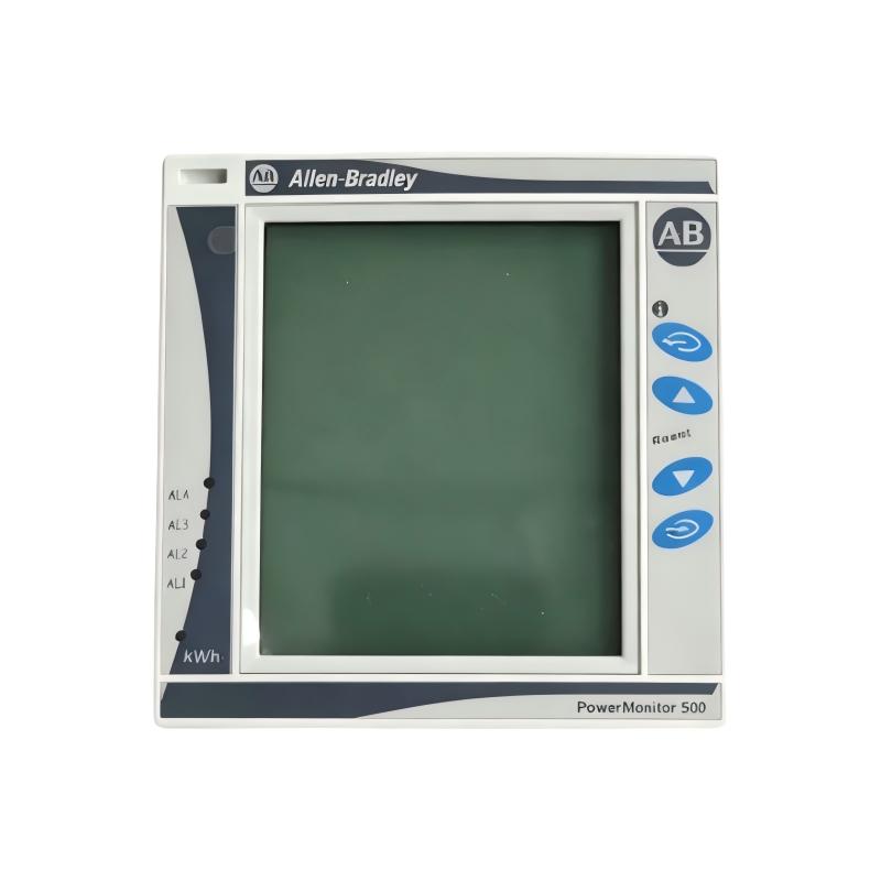
Product Overview
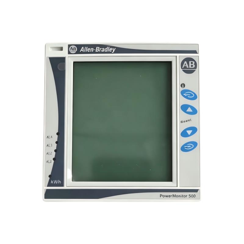
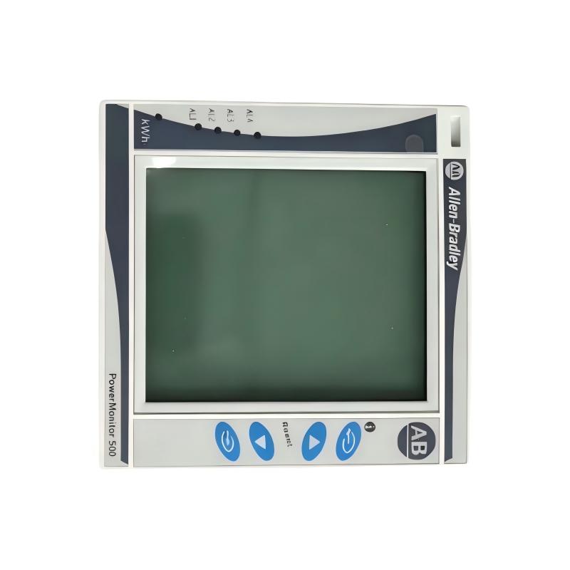
The Allen-Bradley 1420-V2P-ENT PowerMonitor 500 is an industrial power meter manufactured by Rockwell Automation. Designed for electrical distribution monitoring and industrial energy management, it combines electrical measurement capabilities, a built-in LCD display, Ethernet communication, and pulse output functionality in a compact panel-mounted instrument.
Part of the PowerMonitor 500 family, the 1420-V2P-ENT is designed for applications requiring higher-voltage measurement than the V1 product variants. Its catalog specification identifies it as a 600V AC power meter with EtherNet/IP communications and two relay outputs. It is suitable for monitoring compatible single-phase or three-phase electrical systems when correctly configured for the installation.
Electrical measurement data is valuable in manufacturing plants, process facilities, commercial buildings, and industrial utility systems. Monitoring voltage, current, power, power factor, frequency, and accumulated energy helps engineers understand electrical loads and evaluate changes in consumption.
The 1420-V2P-ENT can provide this information locally through its LCD display and communicate data to compatible automation or supervisory systems. This makes it useful for installations where electrical measurements need to be reviewed alongside PLC data, production activity, or facility energy information.
The Ethernet interface supports integration into compatible industrial networks. The documented communication capabilities include EtherNet/IP, with Modbus TCP/IP also supported through the Ethernet interface. The appropriate communication method depends on the controller, software, and network configuration.
When purchasing or replacing this meter, verify the complete catalog number. The V2P-ENT designation is important because voltage measurement ratings and output configurations can differ between PowerMonitor 500 models.
Technical Specifications
| Parameter | Specification |
|---|---|
| Brand | Allen-Bradley |
| Manufacturer | Rockwell Automation |
| Model Number | 1420-V2P-ENT |
| Product Family | PowerMonitor 500 |
| Product Type | Ethernet Power Meter |
| Metering Voltage Class | 600V AC |
| Nominal Voltage Reference | 400V AC line-to-neutral, 600V AC line-to-line |
| Voltage Measurement Range | 160–480V AC line-to-neutral RMS; 277–830V AC line-to-line RMS, subject to the applicable specifications |
| Current Input | 5 A nominal, 6 A maximum |
| Communication Interface | EtherNet/IP |
| Additional Network Protocol | Modbus TCP/IP |
| Display | Built-in LCD |
| Relay/Pulse Outputs | Two relay outputs; confirm configured output function |
| Electrical Measurements | Voltage, current, real power, reactive power, apparent power, power factor, frequency, and energy |
| Energy Measurement | Imported and exported kWh and kVARh |
| Frequency Range | 45–65 Hz |
| Auxiliary Power Supply | 120/240V AC, 50/60 Hz, or 120/240V DC, according to published specifications |
| Front Protection | IP65, NEMA 4X, NEMA 12 |
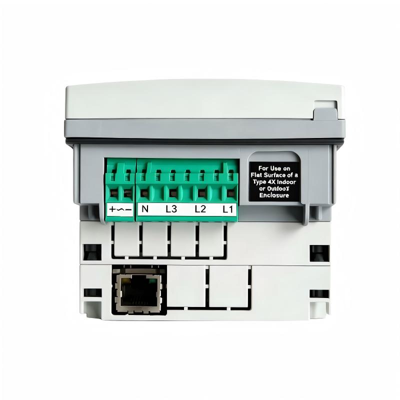
| Mounting | Panel mounting |
| Dimensions | 89.5 × 20 × 63 mm, as supplied; verify the component measured |
| Weight | 0.4 kg, as supplied |
| Typical Applications | Industrial power monitoring, energy management, and electrical distribution analysis |
Dimension clarification: The dimensions supplied appear to describe the serial/Ethernet communication module rather than the complete meter. Rockwell Automation lists the communication module at 89.5 × 63 × 20 mm and the complete module holder at 96 × 96 × 50 mm. Confirm the component and measurement orientation before using these dimensions for panel design or shipping documentation.
Function and Working Principle
1. Electrical Parameter Measurement
The primary function of the 1420-V2P-ENT is to measure electrical quantities in a compatible power distribution system.
Depending on the installation and configuration, the meter can provide information about:
- Line-to-line voltage
- Line-to-neutral voltage
- Phase and system current
- Real power in kW
- Reactive power in kVAR
- Apparent power in kVA
- Power factor
- Electrical frequency
- Imported and exported electrical energy
These measurements help engineers evaluate electrical operating conditions. Voltage and frequency readings provide information about the supply, while current and power measurements help quantify the demand imposed by connected equipment.
Energy values provide a longer-term view of consumption, allowing facilities to compare operating periods and investigate significant changes.
2. Higher-Voltage Measurement Capability
The V2 variant is intended for higher-voltage measurement applications within the PowerMonitor 500 family. Its published nominal voltage reference is 400V AC line-to-neutral and 600V AC line-to-line.
The correct wiring arrangement depends on the electrical system and the meter’s permitted measurement range. Engineers must verify the supply configuration and use suitable measurement connections before energizing the instrument.
The V2P-ENT should not be selected solely because a system is described as three-phase. The actual line-to-line and line-to-neutral voltages must be checked against the meter’s specifications.
3. Power and Energy Calculation
Using voltage and current measurement signals, the meter calculates relevant power parameters and accumulates energy values.
Real power represents the rate at which electrical energy is transferred to perform useful work. Reactive power relates to energy exchanged between the source and reactive elements, while apparent power represents the combined electrical demand expressed in volt-amperes.
Power factor provides additional information about the relationship between real power and apparent power. Together, these measurements can help identify changing load conditions and evaluate the electrical characteristics of connected equipment.
4. EtherNet/IP Communication
The 1420-V2P-ENT includes EtherNet/IP communication capability, allowing measurement data to be integrated into compatible industrial automation systems.
A PLC, industrial computer, or supervisory application can use the supported interface to retrieve electrical information, subject to the correct configuration and data-access method.
The Ethernet interface also supports Modbus TCP/IP according to the product documentation. The chosen protocol should match the intended controller or monitoring application.
5. Relay and Pulse Output Functions
This model includes two relay outputs and supports pulse output functionality. Pulse outputs can be useful for energy-counting applications when configured and connected according to the manufacturer’s instructions.
The exact output behavior, electrical ratings, and configuration should be confirmed against the product manual. Relay outputs should not be treated as substitutes for dedicated safety or electrical protection devices.
Role in Industrial Automation Systems
The Allen-Bradley 1420-V2P-ENT acts as an electrical measurement device within an industrial control and monitoring architecture.
A typical installation includes voltage measurement connections, current transformers, an auxiliary power supply, and an Ethernet connection to the wider automation network. The meter calculates electrical values, displays measurements locally, and provides supported data to connected systems.
PLC Integration
A compatible PLC can collect electrical measurement data for display, logging, or application-specific logic. For example, a plant controller may display the power demand of a production line alongside its operating status.
This allows operators and engineers to compare electrical demand with machine activity. However, the power meter does not replace the PLC or perform the machine’s primary control functions.
HMI and SCADA Integration
An HMI or SCADA application can present electrical measurements in a central interface. Typical displays may include voltage, current, power factor, active power, and accumulated energy.
Where historical logging is available, engineers can compare values across different shifts, production schedules, or operating conditions. The logging and reporting capabilities depend on the connected system rather than on the meter alone.
Energy Management
Electrical measurements can support energy management by identifying consumption patterns and changes in demand. Data from multiple meters may be combined to compare production areas, utility systems, or equipment groups.
For meaningful results, measurement points should be selected carefully, and data should be interpreted alongside production output, equipment duty cycles, and operating schedules.
Industrial Applications
1. Manufacturing Facilities
Manufacturing plants contain motors, drives, heating equipment, production machinery, and other electrical loads. The 1420-V2P-ENT can monitor suitable electrical circuits and provide measurement data for energy reporting and operational analysis.
2. Industrial Electrical Distribution
The meter can be installed in a suitable distribution panel to monitor compatible higher-voltage AC systems. Its measurements can help engineers review current demand, power consumption, power factor, and accumulated energy.
Installation must follow the specified voltage limits, wiring arrangements, and applicable electrical safety requirements.
3. Process Industries
Chemical processing, water treatment, food production, and other process industries use substantial electrical equipment. Power monitoring can help teams compare energy demand and investigate changes in electrical load.
The meter’s data can complement process information, although electrical readings alone do not establish the cause of a process or equipment fault.
4. Commercial and Industrial Buildings
Large buildings may monitor electrical consumption across HVAC systems, pumps, lighting distribution, and other building services. The 1420-V2P-ENT can contribute measurements for a selected circuit where the electrical configuration is suitable.
A broader building energy management system may be needed to consolidate data from multiple meters and produce centralized reports.
5. Energy Audits and Operational Analysis
Energy audits rely on reliable measurements of consumption and demand. The meter’s electrical measurements can help engineers compare operating periods, investigate changes in demand, and evaluate the results of efficiency improvements.
For formal reporting or billing-related applications, verify the required measurement accuracy, certification, and installation method before using the collected data.
6. Equipment Monitoring
Changes in current, power, or power factor can provide useful diagnostic information about connected electrical loads. For example, an unexpected change in power demand may justify inspection of a motor, drive, pump, or production process.
Such measurements should be considered alongside operating history, process data, and other diagnostic evidence.
Installation and System Integration
Installation should be carried out by qualified personnel familiar with industrial electrical measurement equipment.
Step 1: Verify the Model
Confirm the complete catalog number, 1420-V2P-ENT, and check the product label and revision information. Do not confuse this model with V1 variants or other PowerMonitor 500 models that have different voltage ratings or output configurations.
Step 2: Confirm Panel Dimensions
The complete meter uses a front module holder measuring approximately 96 × 96 mm, with a listed depth of 50 mm for the holder. The communication module has separate dimensions.
Verify the required panel cutout, rear clearance, terminal access, and mounting arrangement using the relevant drawing before modifying a control panel.
Step 3: Verify Auxiliary Power
Check the meter’s auxiliary power requirements and terminal assignments against the installation manual and product label. Use a compatible supply and appropriate protective devices.
Do not confuse the auxiliary supply rating with the voltage being measured by the meter.
Step 4: Connect Voltage Measurement Circuits
Verify the system voltage and phase configuration before connecting voltage measurement inputs. Ensure that the measured voltage remains within the specified range.
Use suitable wiring and protective arrangements according to the manufacturer’s instructions and applicable electrical regulations.
Step 5: Install Current Transformers
Select current transformers that match the application and the meter’s current input requirements. The published nominal current input is 5 A, with a maximum of 6 A.
Verify CT ratios, polarity, phase association, and secondary wiring. Incorrect CT configuration can result in misleading current, power, and power factor readings.
Current transformer circuits can be hazardous if handled incorrectly. Follow appropriate safety procedures and never leave a CT secondary open under conditions where this creates a hazard.
Step 6: Configure Ethernet Communication
Connect the meter to the appropriate Ethernet network and configure the required communication settings. Confirm that the PLC, SCADA software, or energy monitoring application supports the selected protocol.
Where EtherNet/IP is used, configure the controller and supported data interface correctly. Where Modbus TCP/IP is used, verify the required data mapping and register definitions.
Step 7: Configure Relay and Pulse Outputs
Review the intended use of the relay outputs and pulse functions. Confirm electrical ratings, wiring, and configuration before connecting external devices.
Test the outputs under controlled conditions and document their intended operation.
Step 8: Validate Measurements
After installation, compare the meter’s readings with expected system conditions or a suitable reference instrument. Verify phase assignments, CT ratios, communication status, and output behavior.
Investigate abnormal readings before relying on the data for energy analysis or operational decisions.
Compatible System Components
The following equipment categories may be used alongside the 1420-V2P-ENT in a suitable monitoring architecture. Compatibility depends on the specific configuration and electrical requirements.
| Component | Function |
|---|---|
| Allen-Bradley PLC | Collects supported measurement data and executes application logic |
| HMI terminal | Displays power measurements and alarms |
| SCADA system | Provides centralized monitoring and historical data collection |
| Industrial Ethernet switch | Connects the meter with compatible network devices |
| Current transformers | Supply current measurement signals |
| Voltage transformers, where required | Adapt measurement circuits to the required range |
| Auxiliary power supply | Supplies the meter’s required control power |
| Electrical distribution panel | Houses the meter and measurement circuits |
| Energy management software | Analyzes and reports electrical consumption |
| Protective devices | Provide electrical protection appropriate to the installation |
Each component should be selected according to its electrical ratings, communication requirements, and intended role. The meter itself is a monitoring instrument, not a replacement for circuit breakers or dedicated protective relays.
Alternative Models and Replacement Considerations
The following related products may be useful when evaluating alternatives. They are not automatically direct replacements for the 1420-V2P-ENT.
| Model | General Description | Selection Consideration |
|---|---|---|
| Allen-Bradley 1420-V2P-ENT | 600V AC PowerMonitor 500 with EtherNet/IP and two relay outputs | Original model; verify the complete configuration |
| Allen-Bradley 1420-V2-ENT | 600V AC PowerMonitor 500 with EtherNet/IP | Compare output configuration; do not assume it has the same pulse/relay functions |
| Allen-Bradley 1420-V2P | 600V AC PowerMonitor 500 with two relay outputs | Does not list the Ethernet communication option |
| Allen-Bradley 1420-V1P-ENT | Lower-voltage PowerMonitor 500 Ethernet meter variant | Voltage measurement rating differs; not an automatic substitute |
| Compatible industrial Ethernet power meter | Third-party electrical monitoring instrument | Verify voltage range, current inputs, communication protocol, accuracy, and mounting |
When choosing a replacement, compare voltage ratings, current inputs, communication capabilities, output functions, auxiliary power, accuracy requirements, and physical dimensions.
A replacement meter may require changes to PLC configuration, network settings, data mapping, or panel wiring. Obtain technical confirmation before substituting a different model in an operating installation.
Key Advantages
Higher-Voltage Measurement Capability
The V2 variant is designed for higher-voltage measurement applications within the PowerMonitor 500 family, making correct model selection particularly important for industrial distribution systems.
Ethernet-Based Monitoring
EtherNet/IP and Modbus TCP/IP support can allow electrical measurements to be incorporated into compatible industrial monitoring and automation systems.
Multiple Electrical Measurements
The meter provides voltage, current, power, power factor, frequency, and energy information, supporting broader electrical analysis than a simple voltage or current indicator.
LCD Display
The built-in LCD allows personnel to inspect measurement values locally during commissioning, routine checks, and troubleshooting.
Relay and Pulse Outputs
Supported output functions provide additional options for external signaling or energy pulse collection, subject to the product’s configuration and ratings.
Energy Management Support
Accumulated energy data can help facilities compare consumption patterns and evaluate operational changes when measurements are collected and analyzed consistently.
Industrial Panel Integration
The panel-mounted design allows the meter to be incorporated into suitable electrical distribution and automation cabinets.
Technical FAQs
1. What is the Allen-Bradley 1420-V2P-ENT?
It is a PowerMonitor 500 Ethernet power meter designed for electrical measurement and monitoring in compatible AC power systems. It includes EtherNet/IP communication and two relay outputs.
2. What is the difference between 1420-V2P-ENT and 1420-V1P-ENT?
The key distinction is the voltage measurement class. The V2P-ENT is specified for a 600V AC class, with a nominal reference of 400V AC line-to-neutral and 600V AC line-to-line. The V1 variant is intended for a lower-voltage range. Always check the complete system voltage before selecting a meter.
3. Does the 1420-V2P-ENT support Modbus TCP/IP?
Yes. The product documentation identifies Modbus TCP/IP support through the Ethernet interface, in addition to EtherNet/IP. The selected protocol must be configured and supported by the connected system.
4. What is the nominal current input?
The published specification lists 5 A nominal and 6 A maximum. Current transformers must be selected and wired according to the meter’s requirements.
5. What auxiliary power supply does it require?
The published specifications list 120/240V AC at 50/60 Hz or 120/240V DC. Verify the exact product label and wiring instructions before applying power.
6. Does it have relay outputs?
Yes. The 1420-V2P-ENT is listed with two relay outputs and supports pulse output functionality. Confirm the exact configuration and contact ratings before connecting external equipment.
7. What are the dimensions and weight?
The supplied dimensions are 89.5 × 20 × 63 mm and the supplied weight is 0.4 kg. The dimensions correspond to the published communication module size when expressed in a different axis order. The complete module holder is approximately 96 × 96 × 50 mm. Confirm which component is being measured.
8. Can it communicate with a PLC?
Yes, it can communicate with compatible systems through its supported Ethernet interface. The PLC or monitoring software must be configured for the selected communication protocol and data-access method.
9. Can the meter monitor three-phase electrical systems?
The PowerMonitor 500 supports three-phase system measurements when configured and connected appropriately. Verify the actual phase arrangement, system voltage, current transformers, and wiring requirements before installation.
10. Is the PowerMonitor 500 a protective relay?
Its primary role is electrical measurement and monitoring. Although it supports alarms and relay outputs, it should not be considered a replacement for dedicated protective devices unless a specific application is explicitly approved for that purpose.
Procurement and Maintenance Recommendations
When sourcing the Allen-Bradley 1420-V2P-ENT, confirm the complete catalog number and ask the supplier to verify the 600V AC version, Ethernet communication capability, and two-relay-output configuration.
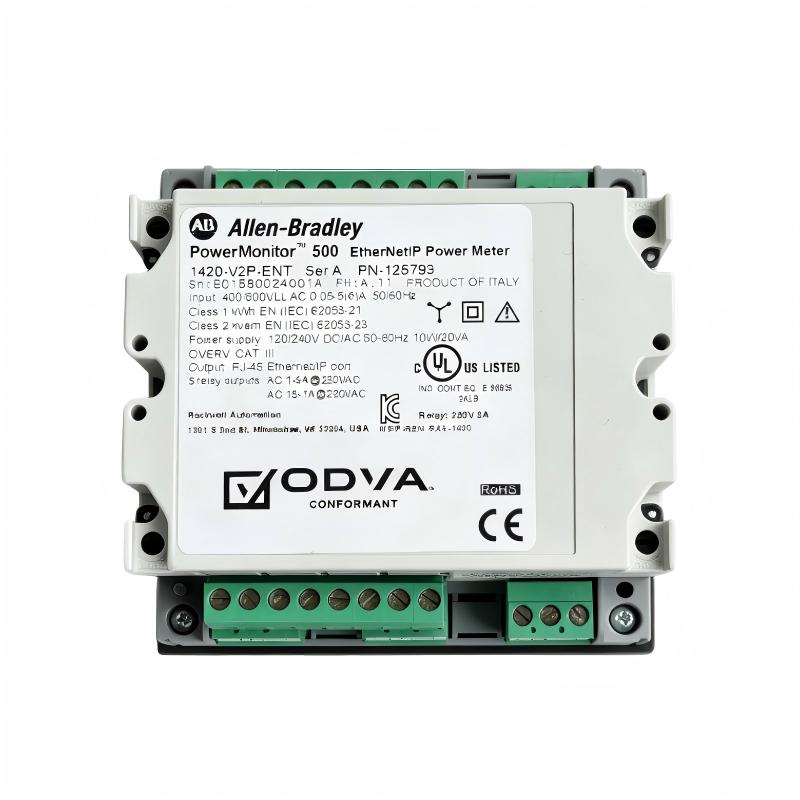
For used or refurbished units, request clear photographs of the product label, front display, terminals, and communication module. Ask about functional testing, warranty coverage, and return conditions.
Before commissioning, verify auxiliary power, voltage measurement connections, current transformer ratios, phase configuration, communication settings, and output behavior. Record the original wiring and configuration when replacing an existing meter.
During operation, review measurements for unexpected changes and compare them with the electrical load and process conditions. Maintain updated wiring diagrams, network settings, and configuration records to support future troubleshooting.
Conclusion
The Allen-Bradley 1420-V2P-ENT PowerMonitor 500 is a 600V AC class industrial power meter designed to measure electrical parameters and provide data through EtherNet/IP and Modbus TCP/IP-compatible communication. Its LCD display, energy measurement functions, configurable alarms, and relay outputs make it suitable for a range of industrial power monitoring applications.
Successful integration depends on selecting the correct voltage variant, installing suitable current transformers, configuring communication correctly, and verifying all electrical connections. Confirm the complete model and physical dimensions before purchasing or replacing the meter.