

ProductPRODUCT
Featured products
Contact Us
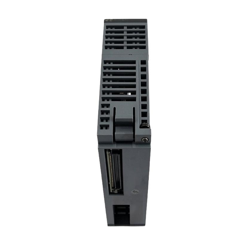
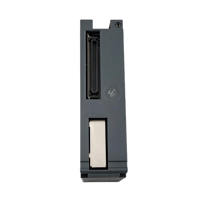
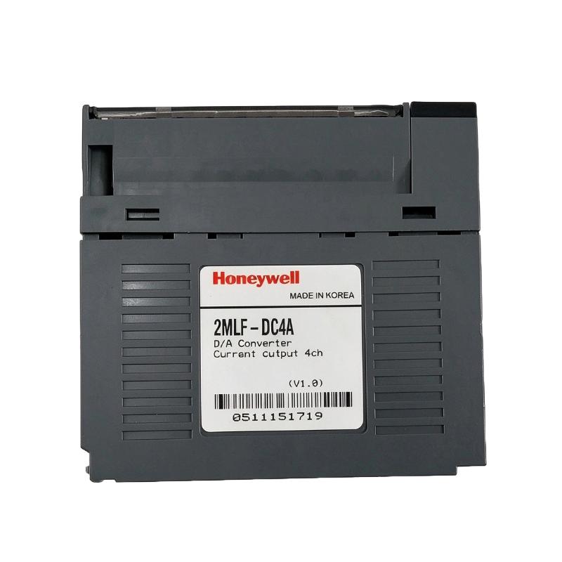
- Honeywell
- 2MLF-DC4A
- D/A Current Output Type
- USA
- 113 × 27 × 98 mm
- 0.15 kg
- Xiamen, China
- New & In Stock
- T/T, PayPal, Western Union
- 1 Year
- 1-3 Working Days
- DHL, UPS, TNT, FedEx and EMS.
- 24-Hour Service
- COO
- 10
Our advantage

Global Logistics
We have a 10-year logistics and express cooperation agreement, so our products can be shipped to any place in the world.

Brand new and original
Our products are imported in bulk from the place of origin. Because of the cooperative relationship, our products are all original and 100% new.

24-hour service
We provide 7*24 hours service to our customers. We will be there whenever you need us.

Price advantage
All our products are priced very favorably because we have our own warehouse and supply.
| Company Information | |||
| [email protected] | |||
| Mobile | +8615980777398 | ||
| +8615980777398 | |||
| 15980777398 |
Product Overview
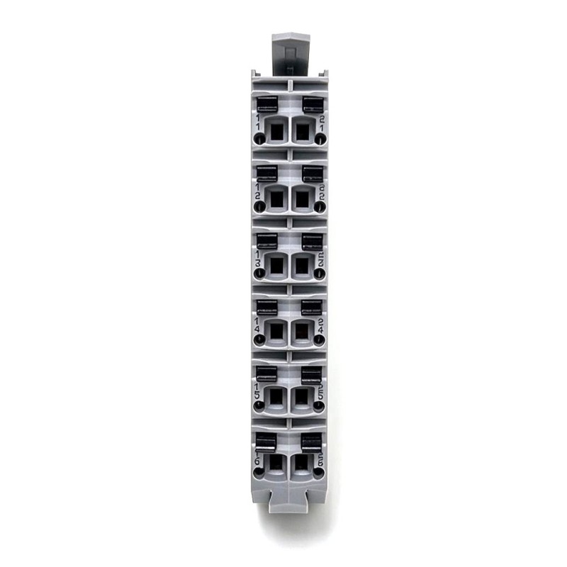
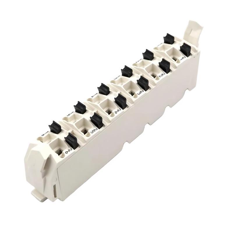
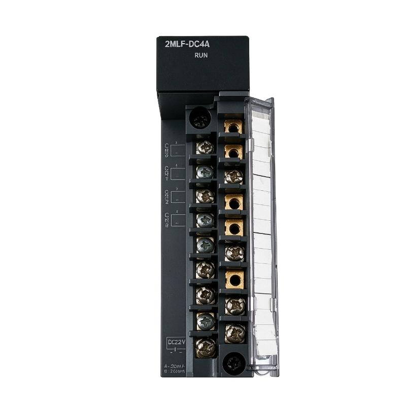
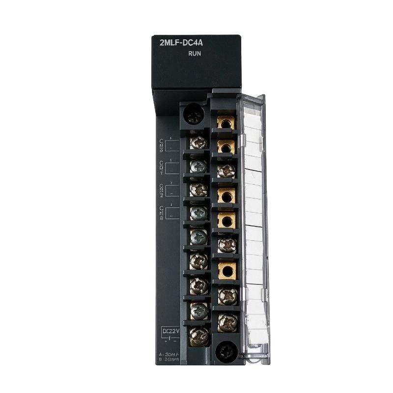
The Honeywell 2MLF-DC4A MasterLogic-200 D/A Current Output Type is a four-channel digital-to-analog output module that converts PLC-generated digital values into industrial current signals. It allows the MasterLogic-200 controller to send continuously adjustable control commands to compatible field devices, including valve positioners, actuator controllers, and other equipment with current-input interfaces.
In a process control cabinet, the module is typically used when the PLC needs to regulate a physical variable rather than simply switch equipment on or off. For example, a PLC controlling a chemical dosing system can calculate the required pump command and send a corresponding 4–20 mA signal through the 2MLF-DC4A to a compatible control interface. Similar arrangements can be used for flow control, pressure regulation, and other processes that rely on analog commands.
The module provides four independently configurable current-output channels. Each channel supports 4–20 mA or 0–20 mA operation, allowing the output range to be selected according to the receiving device and application requirements. The digital values generated by the PLC are converted into corresponding current levels, which the receiving equipment interprets as control commands.
With a specified conversion speed of 250 μs per channel and a resolution of 1/16,000 for the selected output range, the 2MLF-DC4A supports relatively fast analog command updates in conventional PLC applications. Its output accuracy is specified at ±0.2% at 25°C and ±0.3% over the operating temperature range.
The module is particularly useful when several analog-controlled devices must be managed by one controller. Correct selection of the output range, digital data format, and receiving-device load is essential for obtaining the intended control response.
Technical Specifications
| Parameter | Specification |
|---|---|
| Manufacturer | Honeywell |
| Model / Part Number | 2MLF-DC4A |
| Product Family | MasterLogic-200 |
| Product Type | D/A Current Output Module |
| Conversion Function | Digital-to-Analog Conversion |
| Number of Output Channels | 4 |
| Analog Output Signal | DC current |
| Selectable Output Ranges | 4–20 mA, 0–20 mA |
| Maximum Load Resistance | 600 Ω |
| Maximum Resolution | 1/16,000 per output range |
| Resolution at 4–20 mA | 1.0 μA |
| Resolution at 0–20 mA | 1.25 μA |
| Output Accuracy at 25°C | ±0.2% or less |
| Output Accuracy Across Operating Temperature Range | ±0.3% or less |
| Conversion Speed | 250 μs per channel |
| Maximum Absolute Output | ±24 mA |
| Digital Data Representation | Signed 16-bit binary value, with 14-bit data |
| Supported Digital Value Formats | Unsigned, signed, precise, and percentile |
| Output Range Configuration | Individually configurable by channel |
| Output Channel Isolation | No isolation between individual channels |
| Terminal Connection | 18-point terminal |
| Occupied I/O Points | 64 fixed points or 16 variable points |
| Internal Current Consumption | 300 mA at 5 V DC |
| External Supply Requirement | Follow the applicable output-wiring and system power specifications |
| Operating Ambient Temperature | 0–55°C |
| Storage Temperature | −25 to +70°C |
| Dimensions | 113 × 27 × 98 mm |
| Weight | 0.15 kg |
Product Features
- Four analog current outputs: Controls up to four compatible current-command interfaces through a single MasterLogic-200 module.
- Selectable 4–20 mA and 0–20 mA ranges: Supports common industrial current signals used by control valves, actuators, and process equipment.
- 250 μs conversion speed per channel: Supports frequent updates of analog commands, subject to the overall PLC scan cycle and application logic.
- 1/16,000 output resolution: Provides fine digital-to-current conversion increments within the selected output range.
- Specified output accuracy: Offers ±0.2% accuracy at 25°C and ±0.3% across the stated operating temperature range.
- Channel-specific configuration: Allows each channel’s output range and digital representation to be configured for its intended control task.
- Multiple digital value formats: Supports unsigned, signed, precise, and percentile representations for different PLC programming requirements.
- Defined load capability: Supports receiving circuits with a load resistance of up to 600 Ω, subject to the specified operating conditions.
- PLC-integrated operation: Works as part of the MasterLogic-200 I/O architecture, with the CPU calculating and updating the output commands.
Working Principle
The 2MLF-DC4A converts digital values from the PLC program into proportional current signals. The CPU calculates the required output value, and the module generates the corresponding analog current for the connected field device.
A typical control path is:
PLC Control Program → Digital Output Value → 2MLF-DC4A → 4–20 mA Current Loop → Field Control Device
Consider a control valve used to regulate liquid flow. The PLC compares the measured flow with the target value and calculates a new valve command. The 2MLF-DC4A converts the digital command into a current signal, which the valve’s compatible positioner interprets as the requested operating position.
For a 4–20 mA output, the receiving device commonly interprets 4 mA as the lower end of the configured operating range and 20 mA as the upper end. The relationship between current and the physical command depends on the instrument configuration. A 0–20 mA arrangement uses a different scaling convention and must be configured accordingly.
The module supports multiple digital representations. In precise-value mode, for example, the 4–20 mA range corresponds to digital values from 4,000 to 20,000, while the 0–20 mA range corresponds to 0 to 20,000. Other supported formats include unsigned, signed, and percentile values. The PLC program must use the selected format correctly when calculating output commands.
Each channel has a specified conversion speed of 250 μs. This describes the module’s conversion performance per channel; the actual interval between output updates also depends on the PLC scan cycle, program execution, and the control strategy.
The receiving circuit must remain within the module’s specified load capability. For the 2MLF-DC4A, the maximum load resistance is 600 Ω. Excessive loop resistance or incorrect wiring can prevent the output from reaching the commanded current.
The module generates analog commands but does not independently determine the process target or execute the control algorithm. Those tasks belong to the PLC program and the surrounding instrumentation.
Role in the MasterLogic-200 PLC Control Architecture
The 2MLF-DC4A occupies the analog output stage of the PLC system. It converts control values calculated by the CPU into current signals for compatible field equipment, allowing the controller to adjust process variables continuously.
Field Sensors → Analog Input Modules → MasterLogic-200 CPU → 2MLF-DC4A → Current-Controlled Devices
| System Component | Function |
|---|---|
| Honeywell 2MLF-DC4A | Converts four digital commands into analog current outputs |
| MasterLogic-200 CPU | Executes control logic and calculates output commands |
| Analog Input Modules | Acquire process measurements used by the control program |
| PLC Engineering Software | Supports module configuration and application programming |
| Control Valve Positioner | Converts the current command into a corresponding valve-position request |
| Variable-Speed Drive with Analog Input | Receives a compatible current reference when supported by its configuration |
| Actuator Controller | Uses the current signal as a control reference |
| Process Instrumentation | Supplies feedback for closed-loop control |
| Operator Interface | Displays process values and control commands when configured |
| Field Wiring | Connects each output channel to its designated receiving circuit |
The module’s four channels can serve separate control functions within the same PLC application. For example, one channel may command a flow-control valve, another may provide a pressure-control reference, and the remaining channels may serve other compatible devices. Each receiving circuit must be matched to the selected current range and output wiring arrangement.
Industrial Applications
| Application | Typical Use |
|---|---|
| Chemical Processing | Sending current commands to compatible dosing and flow-control equipment |
| Water and Wastewater Treatment | Regulating control valves and other current-controlled process devices |
| Pumping Systems | Supplying analog references to compatible drive or actuator interfaces |
| Pressure Regulation | Sending control commands to pressure-regulating equipment |
| Flow-Control Systems | Adjusting valve position or another compatible flow-control interface |
| Tank-Level Control | Providing analog commands to equipment used in level-control loops |
| Food and Beverage Processing | Controlling compatible process actuators through current signals |
| Packaging Machinery | Sending adjustable analog references to supported machine devices |
| Process Skids | Managing several analog-controlled devices through one PLC module |
| General Manufacturing | Providing current commands for equipment requiring continuous rather than discrete control |
Installation and Maintenance
- Verify the module reference: Confirm that the installed module is 2MLF-DC4A and that the application requires four current-output channels.
- Check the PLC hardware arrangement: Verify that the MasterLogic-200 CPU, base, and module configuration support the intended installation.
- Identify each receiving device: Record the connected valve positioner, actuator controller, drive interface, or other equipment for every output channel.
- Select the current range: Configure each channel for 4–20 mA or 0–20 mA according to the receiving device’s requirements.
- Check the load resistance: Ensure that the complete output circuit remains within the specified maximum load resistance of 600 Ω.
- Inspect the output wiring: Verify terminal assignments, polarity, conductor condition, and the intended current-loop arrangement before energizing the system.
- Configure the digital value format: Select the required unsigned, signed, precise, or percentile representation and confirm that the PLC program uses the same format.
- Review the control scaling: Check that the minimum and maximum digital commands correspond to the intended current range and engineering-unit limits.
- Check the power budget: Account for the module’s specified 5 V DC current consumption when calculating the load on the PLC backplane supply.
- Test each output channel: Use an approved commissioning procedure to verify that commanded digital values produce the expected output currents.
- Investigate incorrect output behavior: Check the selected range, digital scaling, field wiring, load resistance, receiving-device configuration, and module diagnostics before replacing the module.
- Record the commissioning results: Document channel assignments, current ranges, data formats, load conditions, test measurements, and any changes made during maintenance.
Compatible System Components
| Component | Function |
|---|---|
| Honeywell MasterLogic-200 CPU | Calculates control commands and executes the PLC application |
| Compatible MasterLogic-200 Base | Provides the mounting and electrical interface for the output module |
| Honeywell 2MLF-DC4A | Generates four analog current output signals |
| Honeywell 2MLF-DC8A | Provides eight current-output channels for applications requiring additional outputs |
| Honeywell 2MLF-DV4A | Supplies four voltage-output channels for compatible receiving devices |
| Honeywell 2MLF-DC4S | Provides four current-output channels with inter-channel isolation |
| Analog-Controlled Valve Positioner | Converts a compatible current command into a valve-position request |
| Actuator Controller | Receives a configured analog current reference |
| Drive with Compatible Current Input | Accepts a current reference when supported by the drive’s interface |
| Field Wiring and Terminal Assemblies | Connect output channels to their receiving circuits |
| PLC Engineering Software | Configures output ranges, digital formats, and application scaling |
Recommended Related Models
| Model | Product Type | Main Difference |
|---|---|---|
| Honeywell 2MLF-DC4A | D/A Current Output Module | Four current-output channels |
| Honeywell 2MLF-DC8A | D/A Current Output Module | Eight current-output channels |
| Honeywell 2MLF-DC4S | Isolated Current Output Module | Four current-output channels with inter-channel isolation |
| Honeywell 2MLF-DC4H | HART Current Output Module | Four current-output channels with HART support |
| Honeywell 2MLF-DV4A | D/A Voltage Output Module | Four voltage-output channels |
| Honeywell 2MLF-DV8A | D/A Voltage Output Module | Eight voltage-output channels |
Key Advantages
- Provides four current-output channels in one MasterLogic-200 module.
- Supports both 4–20 mA and 0–20 mA output ranges.
- Offers a specified conversion speed of 250 μs per channel.
- Provides 1/16,000 resolution for the selected output range.
- Supports multiple digital value formats for different PLC programming requirements.
- Allows analog control commands to be integrated into the MasterLogic-200 automation architecture.
Technical FAQs
How should the output range be selected for a 4–20 mA control valve positioner?
Set the corresponding channel to 4–20 mA and ensure that the PLC’s digital-value scaling matches the positioner’s configured operating range. Confirm the expected relationship between current and valve command during commissioning.
What limits the number of devices that can be connected to one 2MLF-DC4A channel?
The module provides four output channels, each intended for its designated receiving circuit. The load resistance must remain within the specified 600 Ω maximum, and the wiring arrangement must match the receiving device’s current-input requirements. A single output should not be assumed to support multiple devices without checking the circuit design.
Why can a digital output command be correct while the measured current is incorrect?
The digital value may be valid while the output range, data format, terminal wiring, or load resistance is incorrect. Check the configured current range and the actual output current under the connected load before investigating the PLC control calculation.
When is the 2MLF-DC4S a more suitable alternative?
The 2MLF-DC4S is worth evaluating when the installation requires isolation between output channels. The standard 2MLF-DC4A does not provide inter-channel isolation, so the choice should account for the electrical conditions of the connected circuits and the system’s isolation requirements.