

ProductPRODUCT
Featured products
Contact Us
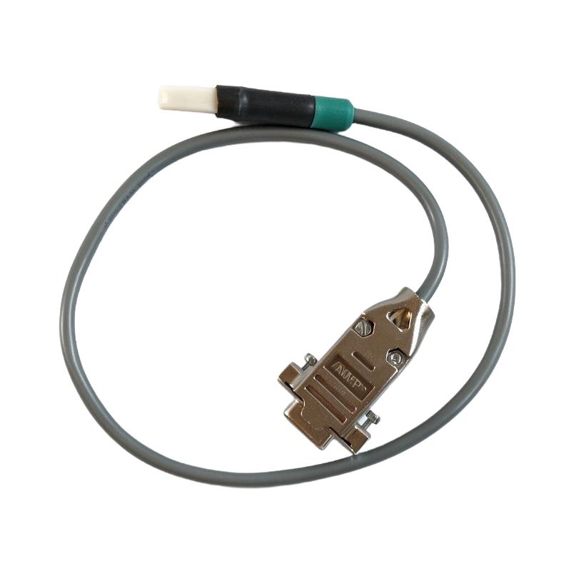
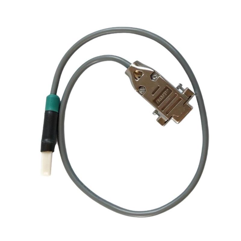
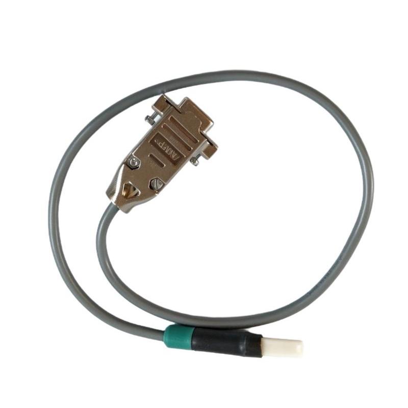
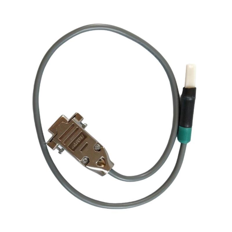
- Honeywell
- 2MLC-F201
- Sync Cable
- USA
- 2 meters
- 3 kg
- Xiamen, China
- New & In Stock
- T/T, PayPal, Western Union
- 1 Year
- 1-3 Working Days
- DHL, UPS, TNT, FedEx and EMS.
- 24-Hour Service
- COO
- 8
Our advantage

Global Logistics
We have a 10-year logistics and express cooperation agreement, so our products can be shipped to any place in the world.

Brand new and original
Our products are imported in bulk from the place of origin. Because of the cooperative relationship, our products are all original and 100% new.

24-hour service
We provide 7*24 hours service to our customers. We will be there whenever you need us.

Price advantage
All our products are priced very favorably because we have our own warehouse and supply.
| Company Information | |||
| [email protected] | |||
| Mobile | +8615980777398 | ||
| +8615980777398 | |||
| 15980777398 |
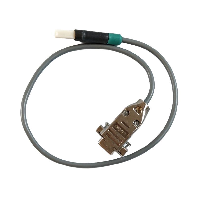
Product Overview
The Honeywell 2MLC-F201 MasterLogic-200 Sync Cable is a multimode fiber optic synchronization cable used in redundant MasterLogic-200R programmable logic controller (PLC) systems. It connects the two CPU modules in a redundant controller arrangement, supporting synchronization between the active control system and its standby counterpart.
In a redundant PLC installation, two CPU systems are configured so that one controls the process while the other remains available to take over if the active system encounters a failure. The synchronization connection is essential to this arrangement because the two systems must coordinate their operating roles and support the intended redundancy behavior.
The 2MLC-F201 uses multimode fiber optic cable with LC connectors and has a specified cable length of 2 meters. The optical connection is suited to the designated MasterLogic-200R synchronization arrangement, where the two CPU modules are connected through the dedicated fiber link.
For example, a process control system may use redundant PLC hardware to supervise pumps, valves, and other equipment whose operation should continue through a controller fault. The 2MLC-F201 provides the synchronization connection between the redundant CPU modules, while the CPUs, power supplies, communication modules, and PLC application implement the broader redundancy scheme.
This cable is different from the 2MLC-E-series expansion I/O cables. The E-series cables connect expansion bases in a supported non-redundant configuration, whereas the 2MLC-F201 is identified as a synchronization cable for the redundant ML200R system.
Technical Specifications
| Parameter | Specification |
|---|---|
| Manufacturer | Honeywell |
| Model / Part Number | 2MLC-F201 |
| Product Family | MasterLogic-200R |
| Product Type | Sync Cable |
| Cable Technology | Multimode Fiber Optic Cable |
| Connector Type | LC |
| Cable Length | 2.0 meters |
| Fiber Core / Cladding Diameter | 50/125 μm |
| Bandwidth | 2000 MHz·km at 850 nm |
| Attenuation | ≤ 3.0 dB/km at 850 nm |
| Numerical Aperture | 0.20 ± 0.015 |
| Compatible System | MasterLogic-200R redundant PLC |
| Maximum Optical Link Distance | 2 km, subject to the applicable system requirements |
| Shipping Weight | 3 kg |
Product Features
- Multimode fiber optic connection: Uses an optical transmission medium for the designated redundant-controller synchronization link.
- LC connectors: Provides the connector interface specified for the 2MLC-F201 cable.
- 2-meter cable length: Suits the intended short-distance connection between redundant CPU modules.
- 50/125 μm fiber: Uses the specified multimode core and cladding dimensions.
- 850 nm optical characteristics: Has a specified bandwidth of 2000 MHz·km and attenuation of no more than 3.0 dB/km at the stated wavelength.
- Redundant-system application: Supports the synchronization arrangement used by compatible MasterLogic-200R hardware.
- Dedicated model identification: Distinguishes the synchronization cable from expansion I/O cables and other optical connection options.
Working Principle
The 2MLC-F201 carries optical signals between the two CPU modules in a supported MasterLogic-200R redundant configuration. The fiber link provides the physical communication path required by the synchronization arrangement.
A simplified system arrangement is:
Active CPU ↔ 2MLC-F201 Fiber Optic Sync Cable ↔ Standby CPU
The redundant system uses two CPU assemblies with their associated power and communication hardware. One CPU operates as the active controller, while the other serves as the standby system. If the active controller fails, the system’s redundancy logic manages the transition to the standby CPU according to the configured operating conditions.
The synchronization cable supports this arrangement by connecting the designated CPU interfaces through a multimode optical link. The cable itself does not decide when a switchover occurs or independently maintain process control; those functions depend on the redundant CPUs, system configuration, and supported control logic.
The fiber connection must be installed between the correct interfaces. An expansion cable or an ordinary Ethernet cable is not a substitute for this dedicated synchronization cable, because the physical interface and intended system function differ.
During commissioning, engineers should confirm the correct redundant CPU arrangement, inspect the LC connectors, and verify that the controller reports the expected synchronization status. A correctly connected cable is one part of the redundancy system, not a replacement for the required CPU configuration and system checks.
Role in the MasterLogic-200R Redundant Control Architecture
The 2MLC-F201 forms the optical synchronization link between the two CPU modules in the redundant PLC arrangement. It works with the redundant CPUs and their associated hardware to support the intended active/standby control structure.
Active CPU ↔ Fiber Optic Synchronization Link ↔ Standby CPU
| System Component | Function |
|---|---|
| Honeywell 2MLC-F201 | Provides the multimode fiber optic synchronization connection |
| 2MLR-CPUH/T | Redundant CPU option using the TP communication configuration |
| 2MLR-CPUH/F | Redundant CPU option using the fiber optic communication configuration |
| Main CPU Bases | House the redundant CPUs and associated modules |
| Redundant Power Supplies | Supply the corresponding redundant controller assemblies |
| Communication Modules | Support the system’s configured communication interfaces |
| Active CPU | Executes the active control application |
| Standby CPU | Provides the backup control role within the configured redundancy scheme |
| PLC Application | Defines process control behavior and supported redundancy operation |
| Engineering and Diagnostic Tools | Support configuration, commissioning, and fault investigation |
Industrial Applications
| Application | Typical Use |
|---|---|
| Power Generation | Connecting redundant PLC CPUs used in plant control systems |
| Water and Wastewater Treatment | Supporting redundant control arrangements for critical pumping and treatment processes |
| Oil and Gas Facilities | Connecting redundant controllers used in process supervision |
| Petrochemical Plants | Supporting controller synchronization in critical automation systems |
| Industrial Utilities | Connecting redundant PLC hardware for essential plant services |
| Continuous Manufacturing | Supporting redundant control arrangements where controller availability is important |
| Process Skids | Connecting redundant CPU assemblies in packaged process equipment |
| Large Pumping Stations | Supporting redundant controller architectures for pump operation |
| Chemical Processing | Connecting the synchronization interfaces of a compatible redundant PLC system |
| Critical Infrastructure Automation | Supporting the physical synchronization link within a configured redundant control system |
Installation and Maintenance
- Verify the model reference: Confirm that the cable is Honeywell 2MLC-F201 and that the installation requires the MasterLogic-200R synchronization cable.
- Check the redundant CPU configuration: Identify the installed CPU models and verify that the system uses a supported redundant arrangement.
- Confirm the connection purpose: Distinguish the synchronization link from the separate expansion I/O and Ethernet connections in the controller system.
- Isolate the equipment as required: Follow the approved maintenance procedure before disconnecting the synchronization cable or accessing the controller interfaces.
- Inspect the LC connectors: Check for damaged connector housings, contaminated end faces, or mechanical defects.
- Protect the fiber: Avoid tight bends, crushing, pulling, or twisting that could damage the optical cable or increase signal loss.
- Connect the correct interfaces: Install the cable between the designated synchronization ports according to the system configuration.
- Secure the cable route: Keep the fiber clear of sharp edges, moving parts, and areas where cabinet doors or other equipment could pinch it.
- Restore the redundant system: Follow the prescribed startup procedure and confirm that both CPU assemblies reach their expected operating states.
- Check synchronization status: Use the supported diagnostic interface to verify that the redundant CPUs report the expected synchronization condition.
- Investigate communication faults: If synchronization fails, inspect the connectors and cable route, then check the CPU configuration and relevant system diagnostics before replacing components.
- Record the installation: Document the cable model, connected CPU interfaces, redundancy configuration, and commissioning results.
Compatible System Components
| Component | Function |
|---|---|
| Honeywell 2MLR-CPUH/T | Redundant CPU with TP communication configuration |
| Honeywell 2MLR-CPUH/F | Redundant CPU with fiber optic communication configuration |
| Honeywell 2MLR-M02P | Main base for supported redundant CPU installations |
| Honeywell 2MLR-M06P | Main base for supported redundant CPU installations |
| Honeywell 2MLR-AC12 / 2MLR-AC22 | Redundant power supply options |
| Honeywell 2MLR-AC13 / 2MLR-AC23 | Higher-current redundant AC power supply options |
| Honeywell 2MLR-DC42 | Redundant DC power supply option |
| Honeywell 2MLC-F201 | Multimode fiber optic synchronization cable |
| Honeywell 2MLR-DBSF | Fiber optic expansion driver for supported redundant configurations |
| Honeywell 2MLR-DBDF | Fiber optic redundant expansion driver for supported configurations |
Recommended Related Models
| Model | Product Type | Main Difference |
|---|---|---|
| Honeywell 2MLC-F201 | MasterLogic-200R Sync Cable | Multimode fiber optic cable with LC connectors, 2.0 m |
| Honeywell 2MLC-F301 | MasterLogic-200R Fiber Optic Cable | Multimode fiber optic cable, 3.0 m |
| Honeywell 2MLC-F501 | MasterLogic-200R Fiber Optic Cable | Multimode fiber optic cable, 5.0 m |
| Honeywell 2MLR-CPUH/F | Redundant CPU | Redundant CPU with fiber optic communication configuration |
| Honeywell 2MLR-CPUH/T | Redundant CPU | Redundant CPU with TP communication configuration |
| Honeywell 2MLR-DBSF | Expansion Driver | Fiber optic expansion driver |
| Honeywell 2MLR-DBDF | Redundant Expansion Driver | Fiber optic redundant expansion driver |
Key Advantages
- Provides the dedicated optical synchronization connection for compatible MasterLogic-200R systems.
- Uses multimode fiber with LC connectors.
- Has a specified 2-meter length for the intended CPU synchronization arrangement.
- Supports the physical connection required by an active/standby redundant-controller architecture.
- Offers defined optical characteristics for cable identification and system selection.
Technical FAQs
What is the purpose of the 2MLC-F201 in a redundant PLC system?
It provides the multimode fiber optic synchronization link between the two CPU modules in a supported MasterLogic-200R redundant arrangement. The redundant CPUs and their configuration manage active/standby operation.
What do the 50/125 μm and 850 nm specifications indicate?
The 50/125 μm figure identifies the fiber core and cladding dimensions. The 850 nm value is the wavelength at which the specified bandwidth and attenuation characteristics are stated.
Can the 2MLC-F201 replace a MasterLogic-200 expansion I/O cable?
No. The 2MLC-F201 is a fiber optic synchronization cable for the redundant ML200R architecture. The 2MLC-E series is used for expansion I/O connections in the designated non-redundant CPU configuration.
What should be checked if the redundant CPUs fail to synchronize?
Inspect the LC connectors and fiber route, confirm that the cable is connected to the correct synchronization interfaces, and review the CPU models and redundancy configuration. The controller diagnostics should be used to identify whether the fault is associated with the optical link or another part of the redundant system.