
NewsNEWCENTER
Featured products
Contact Us
Schneider XCC-1510PS05Y Incremental Encoder Installation and Commissioning Guide
2026-10-20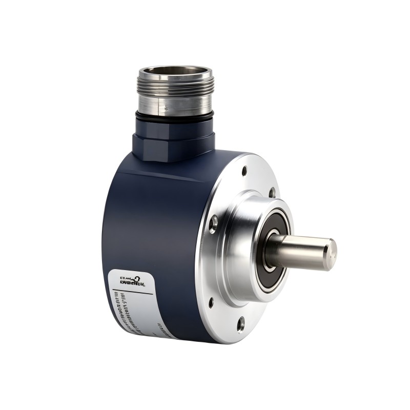
The Schneider Electric XCC-1510PS05Y Incremental Encoder is a rotary position and speed feedback device designed for industrial automation and motion monitoring applications. As part of the OsiSense XCC encoder family, the XCC-1510PS05Y converts mechanical rotation into electrical pulse signals that can be processed by compatible counters, PLC high-speed inputs, motion controllers, and automation equipment.
The Schneider XCC-1510PS05Y features a 58 mm body, a 10 mm solid shaft, 500 points per revolution, a push-pull output stage, and a radial M23 12-pin male connector. Its specified supply voltage range is 5–30 V DC. Correct installation requires attention to mechanical alignment, shaft coupling, electrical compatibility, signal wiring, shielding, and commissioning checks.
Table of Contents
- Product Overview
- Technical Specifications
- Installation Preparation
- Mechanical Installation
- Electrical Connection
- PLC and Controller Integration
- Commissioning and Testing
- Maintenance and Inspection
- Frequently Asked Questions
- Technical Summary
1. Product Overview
The XCC-1510PS05Y is an incremental rotary encoder intended to measure rotational movement. As the shaft turns, the encoder generates electrical pulses that a compatible control system can count to determine relative position, rotational speed, and direction when the required phase-related signals are available and correctly configured.
Incremental encoders are commonly used in conveyor systems, packaging machinery, automated assembly equipment, indexing tables, winding systems, and other machines requiring rotational feedback. The encoder itself does not replace the controller’s counting function. Accurate measurement depends on suitable input hardware, correct configuration, appropriate signal wiring, and reliable mechanical coupling.
2. Technical Specifications
| Parameter | Specification |
|---|---|
| Manufacturer | Schneider Electric |
| Product family | OsiSense XCC |
| Model | XCC-1510PS05Y |
| Product type | Incremental rotary encoder |
| Housing diameter | 58 mm |
| Shaft type | Solid shaft |
| Shaft diameter | 10 mm |
| Resolution | 500 points per revolution |
| Output stage | Type Y, push-pull |
| Supply voltage | 5–30 V DC |
| Electrical connection | Radial M23, 12-pin male connector |
| Maximum rotational speed | 9,000 rpm |
| Maximum output frequency | 300 kHz |
| Number of channels | 3 |
| No-load current consumption | 0–75 mA |
| Maximum output current | 40 mA |
| Protection features | Reverse-polarity and short-circuit protection |
| Housing material | Zamak |
| Approximate weight | 0.465 kg |
These specifications describe the XCC-1510PS05Y variant. Confirm the exact model marking and the applicable connection diagram before selecting a mating connector, configuring a controller, or connecting power. Do not assume that other XCC variants have the same resolution, output stage, or electrical requirements.
3. Installation Preparation
3.1 Verify the Encoder and Application
Before installation, confirm that the encoder resolution, supply voltage, output type, shaft size, and connector arrangement match the application. The XCC-1510PS05Y uses a push-pull output stage. The receiving controller must be compatible with the encoder’s signal levels and electrical characteristics.
Check whether the application requires speed feedback, relative position measurement, direction detection, or reference-position information. Confirm that the selected controller supports the required counting frequency and signal interpretation.
3.2 Prepare the Mechanical Mounting Arrangement
- Inspect the mounting bracket, shaft coupling, driven shaft, and encoder shaft for damage.
- Confirm that the mounting arrangement accommodates the encoder’s 58 mm body and 10 mm solid shaft.
- Select a suitable coupling compatible with the shaft diameters and operating speed.
- Check the alignment between the machine shaft and encoder shaft.
- Ensure that the installation does not impose excessive radial or axial force on the encoder bearings.
3.3 Prepare the Electrical Installation
Verify the DC supply voltage, connector compatibility, cable condition, shielding arrangement, and input specifications of the receiving device. Use a cable and mating connector suitable for the machine environment, cable routing, vibration, and required signal frequency.
3.4 Apply Safety Precautions
Stop the machine and isolate hazardous energy before mounting the encoder, adjusting the coupling, or handling the connector. Follow the site’s lockout/tagout procedure where applicable. Secure rotating machinery against unexpected movement and confirm that all guards are restored before operation.
4. Mechanical Installation
4.1 Secure the Mounting Bracket
Mount the encoder on a rigid bracket designed to support the device without transmitting excessive vibration. The mounting surface should be clean, flat, and correctly positioned relative to the driven shaft.
Check the mounting-hole arrangement against the drawing for the exact XCC variant. Do not drill mounting holes or select fasteners based only on the overall body diameter. Use the appropriate fastener dimensions and engagement depth specified for the mounting arrangement.
4.2 Align the Encoder Shaft
Accurate alignment is important for bearing life and signal stability. Misalignment between the machine shaft and encoder shaft can introduce vibration, excessive bearing load, and premature mechanical wear.
- Position the encoder so that its shaft is aligned with the driven shaft.
- Check angular and parallel alignment before fitting the coupling.
- Install a suitable flexible coupling where appropriate.
- Verify that the coupling can accommodate the expected operating speed and alignment tolerance.
- Secure the encoder mounting hardware according to the applicable mechanical instructions.
- Rotate the mechanism manually, where safe and permitted, to check for interference or binding.
Do not use the encoder shaft to force the machine shaft into alignment. Avoid hammering the shaft, applying excessive axial pressure, or using a coupling that transfers unacceptable radial or axial loads.
4.3 Verify Operating Speed and Load
The published maximum rotational speed for the XCC-1510PS05Y is 9,000 rpm. This is a product limit, not a target operating speed. The actual permitted speed must also account for the coupling, machine design, vibration, installation conditions, and other applicable limits.
Keep the encoder within its specified mechanical load limits. The published reference values are up to 10 daN radial load and 5 daN axial load; confirm the conditions and duration associated with those limits in the applicable product documentation.
5. Electrical Connection
5.1 Confirm the Supply Voltage
The XCC-1510PS05Y has a specified supply range of 5–30 V DC. Select a supply voltage compatible with both the encoder and the receiving controller. Ensure that the voltage measured at the encoder remains within the permitted range after accounting for cable voltage drop and load conditions.
Disconnect power before inserting or removing the encoder connector. Verify the supply polarity and the designated power terminals against the model-specific connector diagram.
5.2 Use the Correct M23 Connector
The encoder uses a radial M23 12-pin male connector. Select a compatible mating connector or prewired cable with the correct pin arrangement and environmental rating. Connector shape alone is not sufficient to establish electrical compatibility.
Do not assume a pin assignment based on a different XCC model or another manufacturer’s encoder. Confirm each connection from the exact product’s wiring diagram before applying power.
5.3 Connect Signal Outputs
The encoder’s push-pull output stage provides electronic switching signals to a compatible receiver. The output circuit, supply voltage, and controller input characteristics must be considered together.
- Verify the function of each required signal channel using the product connection diagram.
- Check that the controller supports the output voltage and signal format.
- Keep signal cables away from high-current motor wiring where practical.
- Use the recommended shield termination and grounding arrangement.
- Check that the controller input current and electrical thresholds are compatible with the encoder outputs.
The maximum specified output current is 40 mA. This value should not be treated as a recommended continuous load for every channel. Follow the manufacturer’s electrical specifications and the receiving device’s requirements.
5.4 Protect Signal Integrity
Encoder signals can be affected by electromagnetic interference, poor shielding, long cable runs, and unsuitable routing. Separate encoder wiring from switching power circuits and motor leads when practical. Where crossings are unavoidable, follow established industrial wiring practices.
Ground the cable shield according to the system design and applicable instructions. Do not use the signal return conductor as a substitute for protective earth. Ensure that the cable and connector provide the required protection for dust, moisture, and mechanical exposure in the application.
6. PLC and Controller Integration
6.1 Configure the Correct Input Type
Connect the encoder to a compatible high-speed counter, encoder interface, or PLC input module. Ordinary digital inputs may not count pulses accurately at the frequencies produced by a rotating encoder. Check the controller’s maximum input frequency and the signal type it supports.
Configure the input channel according to the controller manufacturer’s instructions. Confirm the required signal channels and counting mode before enabling machine operation.
6.2 Understand the Encoder Resolution
The XCC-1510PS05Y has a resolution of 500 points per revolution. This value describes the encoder’s specified resolution; the final count reported by the controller can depend on its counting mode and how it interprets the signals.
For example, if the controller is configured to count 500 events per revolution, a shaft rotating at 600 rpm produces:
Pulse rate = 500 × 600 ÷ 60 = 5,000 events per second.
If the controller uses a multiplication mode that counts multiple signal edges, the reported count rate may be higher. Confirm whether the application uses single-edge, dual-edge, or quadrature counting before calculating the effective counts per revolution.
6.3 Verify Direction and Reference Behavior
If the application requires direction detection, confirm that the controller can interpret the relevant phase-related signals and that the channels are connected correctly. If the application uses a reference or index function, verify the channel assignment and controller configuration from the exact product documentation.
Do not assign connector pins based on generic encoder conventions. The model-specific diagram is the authoritative guide for signal wiring.
7. Commissioning and Testing
7.1 Pre-Power Inspection
- Confirm the encoder model and electrical ratings.
- Check mechanical alignment and coupling security.
- Inspect the M23 connector and cable for damage.
- Verify supply polarity and signal wiring against the correct diagram.
- Confirm that the controller input type and counting frequency are suitable.
- Ensure machine guards and protective devices are in place.
7.2 Apply Power and Check the Signal
Apply power according to the approved commissioning procedure. Check the supply voltage at the encoder using a suitable instrument and verify that the controller recognizes input transitions when the shaft rotates.
If a suitable diagnostic display or monitoring function is available, observe the input count at a low, controlled rotational speed. Compare the count change with the expected mechanical movement and configured counting mode.
7.3 Verify Speed Measurement
Operate the machine at a safe, controlled speed and compare the controller’s speed value with an independent reference where appropriate. Check whether the measured value changes consistently with the machine’s actual speed.
If the measured speed is incorrect by a consistent factor, review the configured resolution, counting mode, scaling calculation, and engineering units. If the reading fluctuates irregularly, investigate signal quality, mechanical vibration, coupling alignment, and electrical interference.
7.4 Complete the Commissioning Record
Record the model number, supply voltage, controller input configuration, configured resolution, cable and connector details, initial count test, speed test, and any application-specific settings. This baseline helps maintenance personnel identify later changes in encoder performance.
8. Maintenance and Inspection
Although an incremental encoder is designed for industrial use, mechanical installation and environmental conditions affect its service life. Inspect the unit at intervals appropriate to the machine’s operating conditions.
- Inspect the mounting bracket for looseness or vibration damage.
- Check the shaft coupling for wear, misalignment, or mechanical play.
- Inspect the M23 connector and cable for damage or contamination.
- Review the cable shield and grounding arrangement.
- Compare encoder readings with established operating values.
- Investigate intermittent counts or unexpected speed changes promptly.
Do not open the encoder housing or attempt unauthorized internal repair. If the shaft, bearings, electronics, or connector are damaged, arrange an appropriate replacement or qualified service evaluation.
9. Frequently Asked Questions
What is the resolution of the Schneider XCC-1510PS05Y?
The specified resolution is 500 points per revolution. The effective controller count depends on the configured counting mode and signal interpretation.
What supply voltage does the encoder require?
The specified supply range is 5–30 V DC. The selected voltage must also be compatible with the receiving controller and must remain within range at the encoder terminals.
Can the encoder connect directly to any PLC input?
No. The receiving input must support the encoder’s push-pull signal characteristics, voltage levels, and required pulse frequency. A suitable high-speed counter or encoder interface may be necessary.
Why does the encoder report an incorrect speed?
Possible causes include an incorrect resolution setting, an unsuitable counting mode, incorrect scaling, signal interference, or mechanical coupling problems. Check the controller configuration and physical installation before replacing the encoder.
Why is the encoder signal missing?
Check the supply voltage, connector engagement, wiring, controller input configuration, and mechanical rotation. Confirm the correct pin assignment from the model-specific wiring diagram before further testing.
Does the XCC-1510PS05Y use a solid shaft?
Yes. This variant has a 10 mm solid shaft. Select a suitable coupling and mounting arrangement that prevent excessive radial or axial loading.
10. Technical Summary
The Schneider Electric XCC-1510PS05Y Incremental Encoder provides rotational feedback for industrial automation systems. Its key characteristics include a 58 mm housing, a 10 mm solid shaft, 500 points per revolution, a push-pull output stage, a radial M23 12-pin male connector, and a 5–30 V DC supply range.
Reliable installation depends on correct mechanical alignment, suitable shaft coupling, compatible controller inputs, verified connector wiring, and proper signal cable routing. During commissioning, check the supply voltage, pulse detection, counting configuration, and speed measurement under controlled operating conditions.
Following these installation and verification practices helps improve encoder signal reliability, reduce mechanical wear, and maintain consistent position and speed feedback in industrial machinery.