

ProductPRODUCT
Featured products
Contact Us
- Allen Bradley
- 20-750-S
- Safe Torque-Off Option Module
- USA
- 120 × 90 × 25 mm
- 0.05 kg
- Xiamen, China
- New & In Stock
- T/T, PayPal, Western Union
- 1 Year
- 1-3 Working Days
- DHL, UPS, TNT, FedEx and EMS.
- 24-Hour Service
- COO
- 5
Our advantage

Global Logistics
We have a 10-year logistics and express cooperation agreement, so our products can be shipped to any place in the world.

Brand new and original
Our products are imported in bulk from the place of origin. Because of the cooperative relationship, our products are all original and 100% new.

24-hour service
We provide 7*24 hours service to our customers. We will be there whenever you need us.

Price advantage
All our products are priced very favorably because we have our own warehouse and supply.
| Company Information | |||
| [email protected] | |||
| Mobile | +8615980777398 | ||
| +8615980777398 | |||
| 15980777398 |
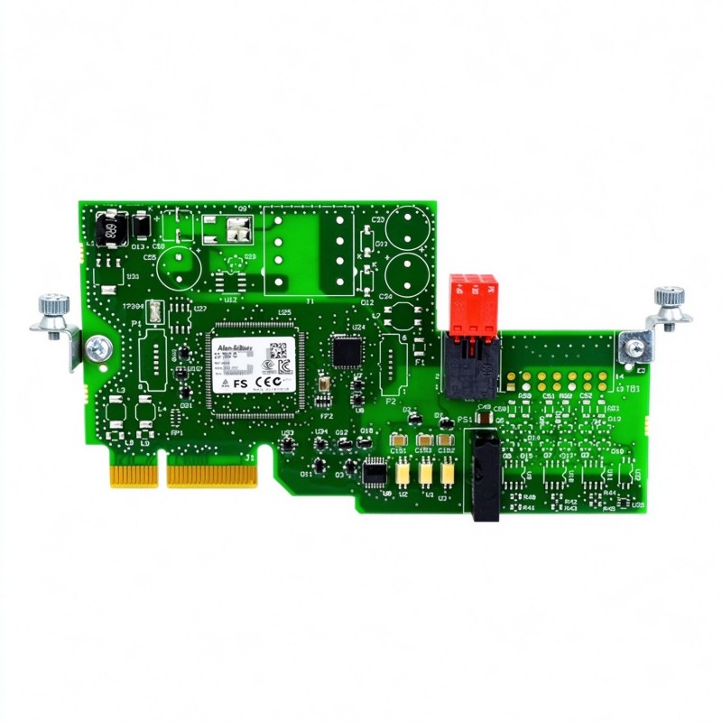
Product Overview
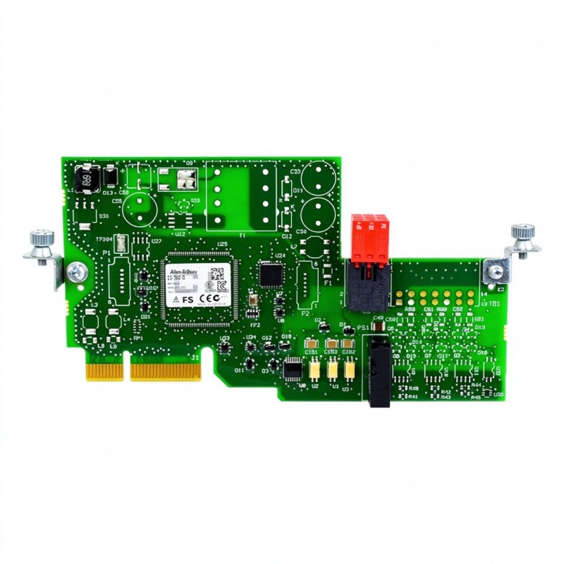
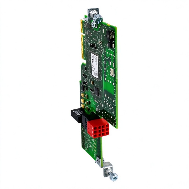
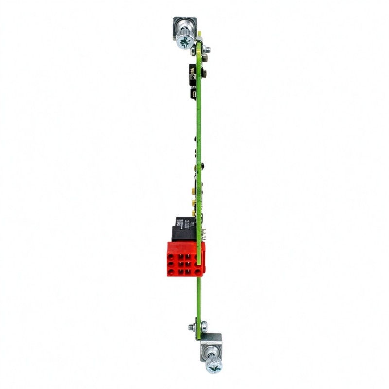
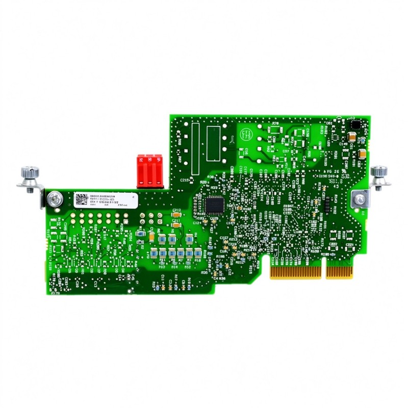
The Allen Bradley 20-750-S PowerFlex 750 Safe Torque-Off Option Module is a safety option for compatible PowerFlex 750-Series AC drives. Its purpose is to prevent the drive from producing motor torque when the Safe Torque Off (STO) function is activated. This allows machine designers to implement safety-related stop functions without relying solely on the drive’s ordinary operational stop command.
In conventional drive control, a stop command instructs the drive to change its operating state according to its configured control logic. STO serves a different purpose: it disables the drive’s ability to generate torque through its motor-control output stage. This distinction matters when machinery must enter a defined safe state during access, maintenance, or a safety-system intervention.
The 20-750-S connects to a supported option port on the host drive and uses dedicated safety input wiring. The module receives signals from an external safety circuit, such as a suitable safety relay or safety controller, and controls the STO function according to its safety architecture. The connected safety circuit must be designed to meet the required performance level and applicable machinery safety standards.
The module supports safety applications up to Category 3, Performance Level e (PL e) under EN ISO 13849-1, and SIL CL3 under applicable functional safety standards. These ratings describe the capability of the safety function under the required conditions; they do not automatically establish the safety rating of the complete machine. The external safety circuit, drive configuration, wiring, validation, and maintenance procedures must all be appropriate for the intended application.
The 20-750-S uses separate safety power and safety-enable connections. The documented interface uses 24V DC signals, with the safety input circuits supplied by a suitable protected extra-low-voltage source. Correct separation of the safety channels, wiring integrity, and appropriate fault monitoring are important to the overall design. A basic PLC output should not be substituted for the required safety-rated control architecture.
The module is intended for use with compatible PowerFlex 750-Series drives, including supported PowerFlex 753 and PowerFlex 755 installations and applicable PowerFlex 755T drive configurations. The host drive’s model, firmware, option-port availability, and application requirements must be checked before selecting the module. Although the 20-750-S can be installed in supported option ports, integrated-motion applications may have specific port-placement requirements.
When STO is activated, the drive prevents the production of motor torque through the safety function. It does not provide electrical isolation from the incoming supply, discharge the DC bus immediately, or guarantee that a rotating load stops instantaneously. A motor may continue to coast, and external mechanical forces can still move the equipment. Applications involving suspended loads, stored mechanical energy, or hazardous motion may require additional braking, isolation, or safety measures.
The 20-750-S is a dedicated safety option rather than a general-purpose communication module. It does not provide the networked safety architecture associated with newer integrated safety options such as the 20-750-S3. Its safety function is implemented through the dedicated safety interface and the compatible drive’s STO capability.
During installation, the drive must be de-energized and the prescribed electrical safety procedures followed. The option module must be seated in a supported port, secured correctly, and wired according to the applicable terminal designations. Safety commissioning must include verification of both the intended stop response and the restoration behavior after the safety circuit is reset.
Typical applications include conveyor systems, packaging machinery, automated assembly equipment, material-handling installations, and other machines where a drive-controlled axis must be brought into a defined torque-disabled state during a safety intervention. The required safety architecture depends on the machine’s hazards, stopping characteristics, and risk assessment.
The Allen Bradley 20-750-S PowerFlex 750 Safe Torque-Off Option Module adds a dedicated drive-based safety function to compatible PowerFlex 750-Series systems, helping engineers implement safety-related torque inhibition while retaining the host drive’s normal motor-control capabilities.
Technical Specifications
| Parameter | Specification |
|---|---|
| Manufacturer | Allen Bradley |
| Model | 20-750-S |
| Product Family | PowerFlex 750-Series |
| Product Type | Safe Torque-Off Option Module |
| Primary Function | Safe Torque Off (STO) |
| Safety Category | Category 3 |
| Performance Level | PL e |
| Safety Integrity Level | SIL CL3 |
| Applicable Standards | EN ISO 13849-1, IEC 61508, IEC 61800-5-2 |
| User Safety Power Supply | 24V DC ±10% |
| Safety Enable Input | 24V DC, 22 mA, short-circuit protected |
| Safety Power Input | 24V DC, 35 mA, short-circuit protected |
| Power Consumption | 4.4 W |
| Safety Interface | Dedicated safety input terminal block |
| Host Interface | PowerFlex 750-Series drive option interface |
| Supported Drive Family | Compatible PowerFlex 753, 755 and applicable 755T drives |
| Installation Ports | Supported drive option ports; Port 6 required for applicable integrated-motion installations |
| STO Function | Disables torque production through the drive safety function |
| Networked Safety | Not a networked STO option |
| Dimensions | 120 × 90 × 25 mm |
| Weight | 0.05 kg |
Product Features
- Drive-based Safe Torque Off: Disables torque production when the configured safety function is activated.
- Category 3 capability: Supports safety applications designed to the applicable Category 3 requirements.
- PL e and SIL CL3 capability: Supports appropriately engineered safety functions at these performance and integrity levels.
- Dedicated safety inputs: Separates safety-enable and safety-power connections from ordinary drive-control commands.
- 24V DC safety interface: Uses a compatible external safety supply for the documented safety input circuits.
- PowerFlex 750-Series integration: Adds STO functionality to supported host drives without replacing the drive’s motor-control functions.
- Supported option-port installation: Fits compatible drive option ports, subject to the host-drive configuration.
- No network dependency for STO activation: Uses its dedicated safety interface rather than requiring a networked safety command.
- Safety-system integration: Can be incorporated into an appropriately designed safety relay or safety-controller architecture.
- Defined commissioning requirements: Allows the safety response and reset behavior to be verified as part of machine validation.
Working Principle
The 20-750-S operates by controlling the Safe Torque Off function of the compatible PowerFlex drive. It receives safety-related signals through its dedicated terminal interface and, when the STO condition is activated, causes the drive to inhibit torque production.
Safety Device → 20-750-S Safety Inputs → Drive STO Function → Torque Production Inhibited
During normal operation, the external safety circuit supplies the required signals to the module’s safety inputs. The module and host drive operate according to their configured safety conditions, allowing the drive to perform its normal motor-control duties while the safety function remains available.
When a safety device detects a hazardous condition or an operator activates an emergency stop, the external safety circuit changes the relevant safety signals. Depending on the system design, this may result from an emergency-stop device, guard interlock, or safety controller. The 20-750-S responds to the safety input condition and activates the drive’s STO function.
Once STO is active, the drive’s power output is controlled so that it cannot produce motor torque through the normal drive-control process. The motor may coast to a stop because the STO function does not itself apply a mechanical brake. The stopping time therefore depends on factors such as motor inertia, load characteristics, friction, and any additional braking equipment.
The safety-power and safety-enable circuits serve distinct roles in the option’s safety interface. The safety-power input supplies the designated 24V DC circuit, while the safety-enable input participates in the control of the STO function. Their wiring must follow the prescribed terminal assignments and safety architecture. The two circuits should not be treated as interchangeable ordinary digital inputs.
The module works in conjunction with the host drive’s internal safety-related functions. It does not independently measure every machine hazard or determine whether an area is safe for personnel. Those responsibilities belong to the overall machine safety system, including sensors, logic, wiring, and any additional devices required by the risk assessment.
After the hazardous condition has been addressed, the safety circuit may permit the STO function to be reset according to the designed procedure. Resetting STO should not automatically cause unexpected machine movement. The application must account for the drive’s start-command behavior, restart interlocks, and any required manual reset or deliberate restart action.
Commissioning verifies that the safety input transitions produce the intended drive response. Tests should include activation, channel behavior where applicable, fault handling, reset behavior, and confirmation that the drive does not restart unexpectedly. The safety function must be validated as part of the complete machine rather than judged solely by whether the option module appears to operate.
Through this dedicated safety interface, the 20-750-S provides a defined method for inhibiting drive-generated torque while allowing the PowerFlex drive to retain its normal control functions when the safety conditions permit operation.
Role in the Industrial Control Architecture
The 20-750-S occupies the drive-safety layer of an industrial control system. It receives signals from the safety architecture and controls the host drive’s STO function independently of ordinary process-control commands.
Emergency-Stop Devices / Guard Interlocks → Safety Relay or Safety Controller → 20-750-S → PowerFlex Drive → Motor
| System Component | Function |
|---|---|
| Allen Bradley 20-750-S | Implements the dedicated STO option function on a compatible drive |
| Safety Relay or Safety Controller | Evaluates safety-device signals and provides the required safety outputs |
| Emergency-Stop Device | Initiates a safety response when activated |
| Guard Interlock | Monitors the state of a machine guard or access point |
| PowerFlex 750-Series Drive | Controls motor operation and inhibits torque when STO is active |
| Industrial Motor | Converts drive output power into mechanical movement |
| Mechanical Brake, Where Required | Provides additional holding or stopping capability when specified by the machine design |
| Standard PLC | Coordinates normal machine sequencing and process control |
| Electrical Isolation Device | Provides the required energy isolation for maintenance where applicable |
| Engineering and Test Equipment | Supports configuration, commissioning, and safety-function validation |
The safety system and standard PLC have different responsibilities. Ordinary control logic must not replace the required safety-rated architecture, and STO must not be treated as a substitute for electrical isolation during servicing.
Industrial Applications
| Application | Typical Use |
|---|---|
| Conveyor Systems | Inhibits drive-generated torque when a safety intervention is required |
| Packaging Machinery | Supports safety-related stopping functions around machine access points |
| Automated Assembly | Provides STO functionality for compatible drive-controlled equipment |
| Material-Handling Equipment | Helps prevent motor torque during defined safety conditions |
| Industrial Processing Lines | Integrates drive torque inhibition into a machine safety architecture |
| Palletizing Systems | Supports safety functions associated with access to hazardous motion |
| Machine Guarding | Works with suitable guard interlocks and safety logic |
| Production Machinery | Provides a drive-based STO function as part of a validated safety system |
| PowerFlex Drive Retrofits | Adds the specified safety option to a compatible existing drive |
| Industrial Automation Cells | Coordinates safety-related torque inhibition with machine-level protective devices |
Installation and Maintenance
- Verify the exact drive model: Confirm that the host drive supports the 20-750-S and that the selected option port is permitted for the application.
- Isolate electrical energy: De-energize the drive and follow the prescribed lockout and verification procedures before installing or removing the module.
- Check the option-port requirements: Confirm the permitted installation position and observe any port restrictions associated with integrated-motion applications.
- Inspect the module connector: Check the module interface and mounting points for damage before installation.
- Secure the option module: Seat the connector fully and tighten the retaining screws to the specified torque using the appropriate tool.
- Use the correct safety supply: Provide the required 24V DC safety power within the documented voltage tolerance and use a suitable protected extra-low-voltage source.
- Follow the terminal assignments: Wire the safety-power, safety-enable, common, and shield connections according to the applicable installation instructions.
- Separate safety and power wiring: Maintain the required separation between control wiring and drive power conductors, and follow the prescribed shielding and grounding practices.
- Verify the safety architecture: Confirm that the external safety relay or controller, input devices, output circuits, and wiring meet the required safety design.
- Test the STO response: Verify that activation of the safety function inhibits torque as intended and that the resulting machine behavior meets the risk assessment.
- Check reset and restart behavior: Confirm that restoring the safety inputs does not cause unexpected motion and that the intended restart procedure operates correctly.
- Document validation results: Record the installed option, wiring configuration, safety test results, drive parameters, and maintenance requirements for future inspections.
If the drive does not respond as expected, check the safety input wiring, external safety supply, module installation, and host-drive compatibility. Do not bypass the safety circuit to restore production. Investigate faults using the prescribed troubleshooting procedure and repeat the required validation after corrective work.
Related Components
| Component | Function |
|---|---|
| Allen Bradley 20-750-S PowerFlex 750 Safe Torque-Off Option Module | Implements the dedicated STO function for compatible PowerFlex 750-Series drives |
| Allen Bradley PowerFlex 753 AC Drive | Provides motor control and supports compatible safety-option integration |
| Allen Bradley PowerFlex 755 AC Drive | Controls motor operation and supports the applicable STO option |
| Allen Bradley 20-750-S-XT | Related STO option variant with additional protection for specified corrosive-gas environments |
| Allen Bradley 20-750-S1 Safe Speed Monitor | Provides additional safety monitoring functions for compatible drive applications |
| Allen Bradley 20-750-S3 Integrated Safety STO Option | Provides an alternative integrated safety architecture for supported PowerFlex 755/755T drives |
| Safety Relay | Evaluates safety inputs and provides the required safety output signals |
| Safety Controller | Executes safety logic for a suitably engineered machine safety system |
| Emergency-Stop Switch | Initiates a safety response when activated |
| Guard Interlock Switch | Monitors access guards and protective doors |
| 24V DC Safety Power Supply | Supplies the required safety-interface power |
| Mechanical Brake | Provides holding or braking functionality when required by the application |
Recommended Related Models
| Model | Product Type | Typical Application |
|---|---|---|
| Allen Bradley 20-750-S | PowerFlex 750 Safe Torque-Off Option Module | Dedicated STO function for compatible PowerFlex 750-Series drives |
| Allen Bradley 20-750-S-XT | PowerFlex 750 Safe Torque-Off Option Module, XT | STO option for supported installations requiring additional environmental protection |
| Allen Bradley 20-750-S1 | PowerFlex 750 Safe Speed Monitor Option Module | Applications requiring supported safe-speed monitoring functions |
| Allen Bradley 20-750-S3 | PowerFlex 755/755T Integrated Safety – Safe Torque-Off Option Module | Integrated safety STO for supported PowerFlex 755/755T drives |
| Allen Bradley 20-750-S4 | PowerFlex 755/755T Integrated Safety Functions Option Module | Supported applications requiring additional integrated drive safety functions |
Key Advantages
- Provides a dedicated Safe Torque Off function for compatible PowerFlex 750-Series drives.
- Supports appropriately engineered Category 3, PL e, and SIL CL3 safety applications.
- Uses dedicated 24V DC safety inputs rather than relying on ordinary process-control commands.
- Integrates with suitable external safety relays and safety controllers.
- Allows drive torque inhibition without replacing the host drive’s normal motor-control functions.
- Supports safety-related machine stopping architectures when correctly installed and validated.
Technical FAQs
Does the 20-750-S stop the motor immediately when STO is activated?
No. STO inhibits drive-generated torque, but the motor may continue to coast under its existing momentum or external mechanical forces. If a defined stopping time or holding function is required, the machine may need an additional braking or safety arrangement.
Can the 20-750-S replace an emergency-stop switch or safety relay?
No. The module implements the drive-side STO function. Emergency-stop devices, guard interlocks, and the required safety logic must still be selected and configured as part of the complete safety architecture. The overall system must be validated against the applicable risk assessment and standards.
What is the difference between the 20-750-S and the 20-750-S3?
The 20-750-S uses a dedicated safety input interface for the STO function. The 20-750-S3 is an integrated safety option for supported PowerFlex 755/755T drives and uses a different safety architecture and terminal arrangement. They are not interchangeable without checking drive compatibility, wiring, configuration, and safety requirements.
What must be verified after replacing a 20-750-S module?
Confirm the module’s compatibility and installation, inspect the safety wiring, and verify the external safety supply. Then test the STO activation response, fault handling, reset behavior, and prevention of unexpected restart. The safety function must be revalidated after replacement before the machine returns to normal operation.