

ProductPRODUCT
Featured products
Contact Us
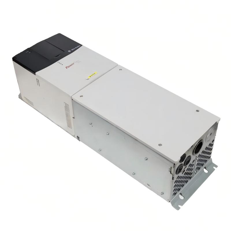
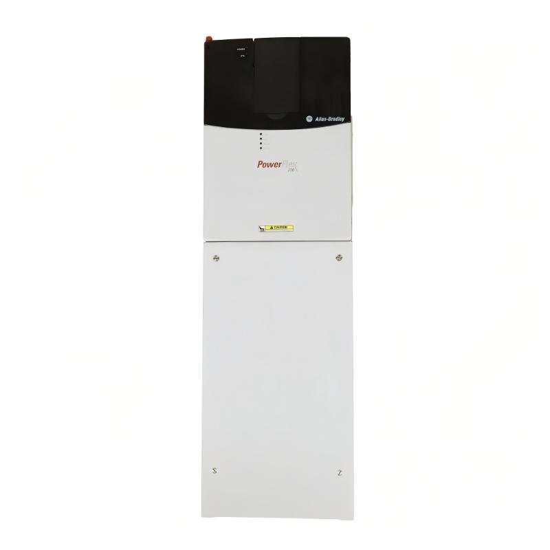
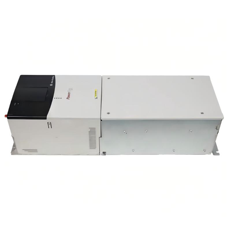
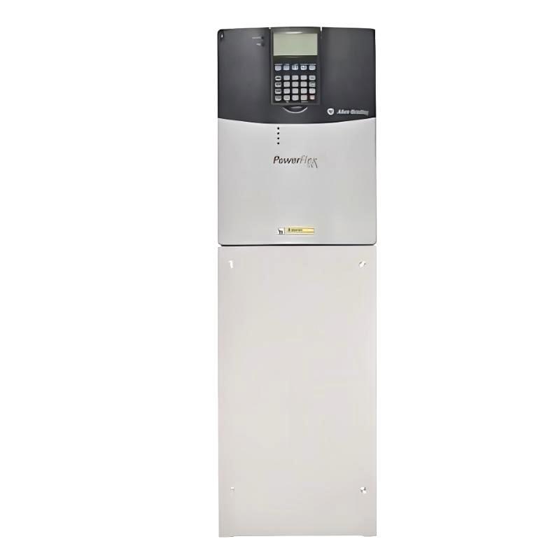
- Allen Bradley
- 20BB080A0ANNANC0
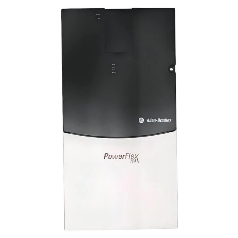
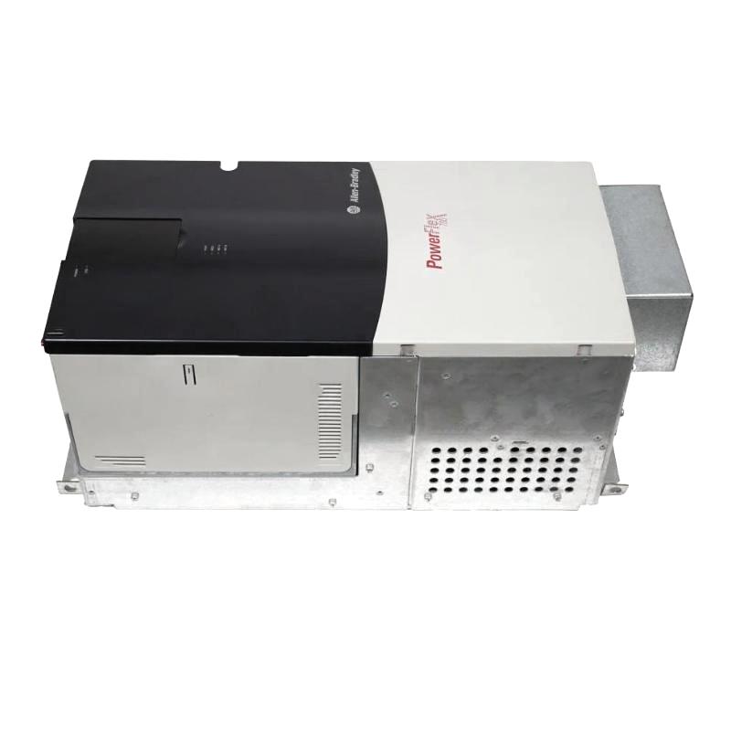
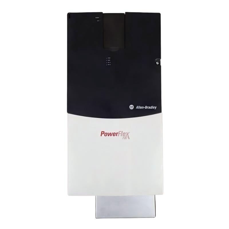
- PowerFlex 700 AC Drive
- USA
- 758.8 × 220 × 201.7 mm
- 24.49 kg
- Xiamen, China
- New & In Stock
- T/T, PayPal, Western Union
- 1 Year
- 1-3 Working Days
- DHL, UPS, TNT, FedEx and EMS.
- 24-Hour Service
- COO
- 4
Our advantage

Global Logistics
We have a 10-year logistics and express cooperation agreement, so our products can be shipped to any place in the world.

Brand new and original
Our products are imported in bulk from the place of origin. Because of the cooperative relationship, our products are all original and 100% new.

24-hour service
We provide 7*24 hours service to our customers. We will be there whenever you need us.

Price advantage
All our products are priced very favorably because we have our own warehouse and supply.
| Company Information | |||
| [email protected] | |||
| Mobile | +8615980777398 | ||
| +8615980777398 | |||
| 15980777398 |
Product Overview
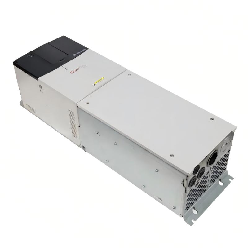
The Allen Bradley 20BB080A0ANNANC0 PowerFlex 700 AC Drive is an adjustable-frequency drive for industrial three-phase AC motor applications. It belongs to the PowerFlex 700 20B family and is configured for the 240 V class, with an 80 A rated output current. Its power ratings are 30 HP for normal-duty operation and 25 HP for heavy-duty operation, making it suitable for compatible motor loads that require variable-speed control and coordinated operation within an industrial process.
This catalog configuration combines vector control with standard 24V I/O, an IP20 / NEMA Type 1 enclosure arrangement, conformally coated electronics, and a second-environment EMC filter configuration. It is supplied without a Human Interface Module (HIM), brake IGBT, internal drive-mounted braking resistor, communication module, or feedback option. These details distinguish this model from other PowerFlex 700 drives with similar current ratings but different control and hardware arrangements.
The PowerFlex 700 regulates motor operation by adjusting the electrical output supplied to the motor. Instead of operating continuously at the frequency of the incoming power supply, the drive can change the output frequency and voltage according to the selected control method and configured reference. This allows a machine to adjust motor speed to suit production requirements, material flow, or changing process conditions.
The vector-control configuration is relevant where motor response and load variation must be considered alongside the requested speed. Appropriate motor data and drive parameters are necessary for the control system to respond correctly as operating conditions change. The actual performance depends on the motor, selected control mode, parameter setup, and mechanical characteristics of the application.
With an 80 A output rating, the 20BB080A0ANNANC0 occupies a higher-current position than the 70 A 20BB070A0ANNANC0 configuration. The distinction is important when replacing a drive in an existing machine. A higher current rating alone does not establish that a replacement is suitable: incoming voltage, motor requirements, duty rating, protective devices, braking needs, and control configuration must also be checked.
The drive’s 24V I/O provides a practical interface for external control circuits. A PLC or relay-based control system can use the assigned inputs to initiate operation, select commands, or coordinate drive behavior with other equipment. The available input and output functions depend on the configured terminal assignments and drive parameters. Because this catalog number has no communication module installed, a network connection should not be assumed to be available without a separate compatibility assessment.
The blank-plate configuration means that a drive-mounted HIM is not supplied. The commissioning plan must therefore include a suitable supported method for configuring parameters, monitoring drive status, and investigating faults. The absence of the HIM does not remove the drive’s programmable functions, but it changes the hardware supplied with the unit and should be considered when planning installation and maintenance.
This model also lacks a brake IGBT and an internal drive-mounted braking resistor. That distinction matters in applications involving frequent deceleration, high-inertia loads, or mechanical systems that return energy to the drive during slowing. If the process requires dynamic braking, engineers must determine whether a compatible external braking arrangement is needed and verify that the complete configuration meets the drive’s installation requirements.
The conformally coated electronic assemblies provide additional protection against certain environmental contaminants. However, the coating does not eliminate the need for appropriate environmental protection. The IP20 / NEMA Type 1 arrangement must be installed in an environment consistent with the drive’s ratings, with adequate ventilation and protection from unsuitable moisture, dust, and other contaminants.
The 20BB080A0ANNANC0 can serve as the motor-control element in a machine architecture where the PLC handles process logic and the drive executes motor commands. Standard I/O can coordinate basic operating functions, while additional communication capabilities must be assessed separately if the machine requires network-based diagnostics or control. The appropriate configuration depends on the installed hardware and the wider automation system.
For replacement and new-installation projects, the complete catalog number should be used when comparing equipment. The 80 A rating, 30 HP normal-duty rating, 25 HP heavy-duty rating, vector-control arrangement, missing braking hardware, and absence of an installed communication module all affect system compatibility. Checking these points before installation helps avoid configuration mismatches and unnecessary commissioning work.
Technical Specifications
| Parameter | Specification |
|---|---|
| Manufacturer | Allen Bradley |
| Model | 20BB080A0ANNANC0 |
| Product Family | PowerFlex 700 |
| Product Type | Adjustable Frequency AC Drive |
| Drive Series | 20B |
| Input Voltage Class | 240 V |
| Input Voltage Range | 208–240 V AC |
| Input Phase | 3-phase |
| Rated Output Current | 80 A |
| Normal-Duty Power Rating | 30 HP |
| Heavy-Duty Power Rating | 25 HP |
| Control Method | Vector Control |
| Standard I/O | 24V I/O |
| Enclosure Rating | IP20 / NEMA Type 1 |
| Conformal Coating | Yes |
| EMC Filter Configuration | Second-environment filter |
| Human Interface Module (HIM) | Not included; blank plate configuration |
| Brake IGBT | Not included |
| Internal Drive-Mounted Brake Resistor | Not included |
| Communication Module | Not installed |
| Feedback Option | Not included |
| Analog Inputs | 2 |
| Analog Outputs | 2 |
| Digital Inputs | 6 |
| Digital Outputs | 3 |
| Maximum Output Frequency | Up to 400 Hz, subject to drive configuration |
| Mounting | Industrial panel installation |
| Dimensions | 758.8 × 220 × 201.7 mm |
| Weight | 24.49 kg |
Product Features
- 80 A rated output current: Supports compatible motor applications within the drive’s specified current and duty limits.
- 30 HP normal-duty rating: Provides the specified power rating for applications operating under normal-duty conditions.
- 25 HP heavy-duty rating: Supports the lower heavy-duty rating for applications with more demanding load characteristics.
- Vector-control operation: Regulates motor behavior according to the selected control mode and configured motor parameters.
- 240 V-class three-phase input: Suits compatible industrial power systems within the specified voltage range.
- 24V I/O interface: Supports external run commands, control signals, and configured status functions.
- Conformally coated electronics: Adds protection against certain environmental contaminants.
- Second-environment EMC filter configuration: Supports the specified electromagnetic compatibility arrangement when installed according to the applicable requirements.
- No installed communication module: Requires separate evaluation of network-control requirements.
- No internal braking hardware: Allows braking needs to be assessed against the load’s deceleration and regenerative-energy characteristics.
Working Principle
The 20BB080A0ANNANC0 converts incoming three-phase AC power into a controlled electrical output for the connected motor. Its internal power-conversion stages and vector-control functions work together to regulate motor operation according to the configured reference, operating mode, and protection limits.
Three-Phase AC Input → Rectifier → DC Bus → Inverter → AC Motor
The incoming supply enters the drive’s rectifier stage, where AC power is converted into DC power. The DC bus provides the intermediate electrical link for the inverter stage. The inverter then generates a controlled AC output whose voltage and frequency are adjusted to meet the motor’s operating requirements.
In vector-control operation, the drive uses its configured motor data and control calculations to manage the relationship between motor flux, torque, and speed. This allows the drive to respond to changing commands and load conditions according to its selected control mode. Correct motor identification data and parameter settings are essential; an unsuitable configuration can lead to poor response, excessive current, or unexpected operating behavior.
When a PLC or external control circuit issues a speed reference or run command, the drive processes the signal according to the configured command source. The requested operating point is constrained by the programmed acceleration and deceleration ramps, current limits, frequency limits, and other applicable parameters. The inverter adjusts its output as the motor approaches the requested speed.
The standard 24V I/O provides a connection between the drive and external machine-control devices. Assigned inputs may be used for run commands, direction selection, or other supported functions. Configured outputs can provide selected status information to the surrounding control system. The exact behavior depends on the wiring arrangement and the parameter assignments used during commissioning.
The drive’s 80 A rating must be considered in conjunction with its duty-specific horsepower ratings. Motor selection cannot be based on horsepower alone because motor current, operating conditions, overload requirements, and the drive’s permitted operating range also affect suitability. Engineers should verify the motor nameplate and applicable drive ratings before connecting the load.
The lack of an installed communication module means that network-based control is not automatically available in this configuration. The drive can still use its standard I/O, but any requirement for a fieldbus or industrial Ethernet connection must be assessed separately. A suitable option, compatible controller configuration, and appropriate commissioning procedure may be needed.
During deceleration, the motor may return energy to the drive’s DC bus. Because the 20BB080A0ANNANC0 does not include a brake IGBT or internal drive-mounted braking resistor, applications that generate significant regenerative energy require particular attention. Depending on the load and stopping profile, the system may need compatible external braking equipment or revised deceleration settings.
The drive’s internal control and protection functions monitor operating conditions and respond according to the configured limits. If a fault occurs, diagnosis should include the incoming supply, motor wiring, external command signals, motor parameters, and mechanical load. A fault should not automatically be attributed to the power stage without checking the surrounding control and installation conditions.
The HIM-free configuration also affects how commissioning information is entered and how operating status is accessed. A suitable supported interface must be available to configure the control source, motor data, ramps, and I/O assignments. These settings should be verified before the motor is operated under production load.
Through this combination of power conversion, vector control, and configurable I/O, the 20BB080A0ANNANC0 provides adjustable-speed operation for compatible industrial motors while allowing the surrounding control system to coordinate machine behavior.
Role in the Industrial Control Architecture
The 20BB080A0ANNANC0 occupies the motor-control layer of an industrial automation system. It converts the electrical supply into controlled motor power and responds to commands from external control devices through its configured I/O.
Three-Phase AC Supply → PowerFlex 700 Drive → AC Motor
PLC / Relay Control → 24V I/O → PowerFlex 700 → Motor Operation
| System Component | Function |
|---|---|
| Allen Bradley 20BB080A0ANNANC0 | Regulates motor operation according to the configured control mode and commands |
| Three-Phase AC Supply | Provides the input power required by the drive |
| Industrial PLC | Executes process logic and coordinates equipment operation |
| 24V Control Circuit | Supplies compatible external commands to assigned drive inputs |
| AC Motor | Converts the drive’s controlled electrical output into mechanical movement |
| Process Sensors | Supply machine-state or process measurements to the controller |
| Protective Devices | Provide the required upstream electrical protection |
| External Braking Equipment, Where Required | Addresses braking energy or stopping requirements when correctly engineered |
| Supported Programming Interface | Provides access to drive parameters, diagnostics, and commissioning functions |
| Electrical Cabinet | Provides the required installation environment and organizes power and control wiring |
The PLC manages the machine sequence, while the PowerFlex 700 performs the motor-control functions. Communication and braking requirements must be evaluated separately because this particular catalog configuration does not include those additional drive options.
Industrial Applications
| Application | Typical Use |
|---|---|
| Conveyor Systems | Adjusts motor speed to match material throughput and production sequencing |
| Industrial Pumps | Regulates pump operation according to process demand |
| Fans and Blowers | Varies motor speed to control airflow |
| Mixers and Agitators | Controls motor operation as material resistance changes |
| Material-Handling Equipment | Coordinates drive operation with external control signals |
| Packaging Machinery | Regulates compatible motors used in product transport and machine cycles |
| Manufacturing Lines | Matches motor operation to production requirements and machine interlocks |
| Process Equipment | Provides variable-speed operation for compatible industrial loads |
| Machine Retrofit Projects | Replaces a compatible drive when electrical and configuration requirements match |
| General Industrial Motor Control | Provides adjustable-frequency operation for compatible three-phase AC motors |
Installation and Maintenance
- Verify the complete catalog number: Confirm that the installed or replacement unit is 20BB080A0ANNANC0, including its voltage, current, duty rating, and option configuration.
- Check the incoming power supply: Verify compatibility with the drive’s 208–240 V-class three-phase input requirements and applicable electrical installation rules.
- Confirm motor ratings: Compare the motor nameplate voltage, rated current, power, and frequency with the drive’s specifications before connecting the motor.
- Isolate electrical energy: Disconnect the supply and follow the prescribed lockout and DC-bus discharge verification procedures before servicing the drive.
- Inspect the enclosure environment: Confirm that the IP20 / NEMA Type 1 arrangement has appropriate environmental protection and sufficient cooling for the installation.
- Check grounding and wiring: Verify protective grounding, incoming power connections, motor terminals, control wiring, and terminal tightness.
- Enter the correct motor parameters: Configure the drive using the connected motor’s nameplate information and the control mode required by the application.
- Verify I/O assignments: Check the configured command source and confirm that the external 24V control signals match the intended terminal assignments.
- Arrange parameter access: Because no HIM is included, confirm that a supported programming or diagnostic method is available before commissioning.
- Assess the braking arrangement: Evaluate the motor’s inertia, deceleration profile, and regenerative-energy behavior to determine whether additional braking hardware is required.
- Test under controlled conditions: Verify starting, speed changes, acceleration, deceleration, stop commands, interlocks, and fault responses before returning the machine to production.
- Maintain configuration records: Record the drive identification, parameter settings, motor data, I/O assignments, wiring diagrams, and service history for future maintenance.
If the drive does not start, check the supply, control source, input assignments, and drive status. If overcurrent or DC-bus faults occur during deceleration, examine the load characteristics, ramp settings, and braking requirements. Any corrective changes should remain within the drive’s documented operating limits.
Related Components
| Component | Function |
|---|---|
| Allen Bradley 20BB080A0ANNANC0 PowerFlex 700 AC Drive | Provides adjustable-speed control for compatible industrial AC motors |
| Compatible Three-Phase AC Motor | Converts controlled electrical power into mechanical motion |
| Industrial PLC | Coordinates drive commands with machine sequences and interlocks |
| 24V DC Control Supply | Supplies compatible external control circuits |
| Control Relays | Provide switching functions within the designed control circuit |
| Input Circuit Breaker or Fuses | Provide upstream electrical protection selected for the installation |
| Supported Programming Interface | Enables drive configuration and diagnostic access |
| Compatible Communication Option | Adds supported network connectivity when required |
| External Braking Equipment | Addresses braking requirements where the application needs additional energy dissipation |
| Motor Power Cable | Connects the drive output to the motor |
| Control Wiring | Carries external commands and configured status signals |
| Industrial Control Cabinet | Provides the required mounting and environmental protection |
Recommended Related Models
| Model | Product Type | Typical Application |
|---|---|---|
| Allen Bradley 20BB070A0ANNANC0 | PowerFlex 700 AC Drive | Related 70 A, 240 V-class configuration for compatible lower-current applications |
| Allen Bradley 20BB080A0ANNANC0 | PowerFlex 700 AC Drive | 80 A configuration with vector control and 24V I/O |
| Allen Bradley 20BB104A0ANNANC0 | PowerFlex 700 AC Drive | Higher-current 240 V-class configuration for compatible motor applications |
| Allen Bradley 20BB080A0AYNANC0 | PowerFlex 700 AC Drive | Related 80 A configuration with a different braking-option arrangement |
| Allen Bradley 20BD080A0ANNANC0 | PowerFlex 700 AC Drive | Related 400 V-class drive configuration; verify the complete catalog number and electrical requirements |
Key Advantages
- Provides an 80 A output-current rating for compatible industrial motor applications.
- Supports 30 HP normal-duty and 25 HP heavy-duty operation in the specified voltage class.
- Uses vector control for motor regulation under changing operating conditions.
- Provides standard 24V I/O for integration with external machine-control circuits.
- Includes conformally coated electronics and the specified second-environment EMC filter configuration.
- Allows braking and network communication requirements to be assessed separately for the application.
Technical FAQs
When should the 20BB080A0ANNANC0 be selected instead of the 20BB070A0ANNANC0?
The 20BB080A0ANNANC0 has an 80 A output-current rating, compared with 70 A for the 20BB070A0ANNANC0. Its ratings are 30 HP normal duty and 25 HP heavy duty. Selection should be based on the motor’s rated current, duty requirements, voltage, load profile, and the complete drive configuration rather than horsepower alone.
Can the drive accept a network command without an additional communication option?
This catalog configuration does not include an installed communication module. Its standard 24V I/O supports compatible external control signals, while network-based control requires a separate assessment of compatible hardware and system configuration.
What needs to be considered when the application requires frequent deceleration?
The drive does not include a brake IGBT or an internal drive-mounted braking resistor. Engineers should evaluate motor inertia, stopping frequency, deceleration time, and regenerative energy. If additional braking is required, the selected arrangement must be compatible with the drive and the machine’s operating conditions.
How does the missing HIM affect commissioning and maintenance?
The drive is supplied with a blank plate rather than a drive-mounted HIM. A supported alternative method must therefore be available for entering parameters, checking operating status, and diagnosing faults. The commissioning procedure should include verification of motor data, command sources, I/O assignments, and protection settings.