

ProductPRODUCT
Featured products
Contact Us
- Allen Bradley
- 1492-TIFM40F-24-2
- Termination Module
- USA
- 130 × 50 × 58 mm
- 0.21 kg
- Xiamen, China
- New & In Stock
- T/T, PayPal, Western Union
- 1 Year
- 1-3 Working Days
- DHL, UPS, TNT, FedEx and EMS.
- 24-Hour Service
- COO
- 5
Our advantage

Global Logistics
We have a 10-year logistics and express cooperation agreement, so our products can be shipped to any place in the world.

Brand new and original
Our products are imported in bulk from the place of origin. Because of the cooperative relationship, our products are all original and 100% new.

24-hour service
We provide 7*24 hours service to our customers. We will be there whenever you need us.

Price advantage
All our products are priced very favorably because we have our own warehouse and supply.
| Company Information | |||
| [email protected] | |||
| Mobile | +8615980777398 | ||
| +8615980777398 | |||
| 15980777398 |
Product Overview
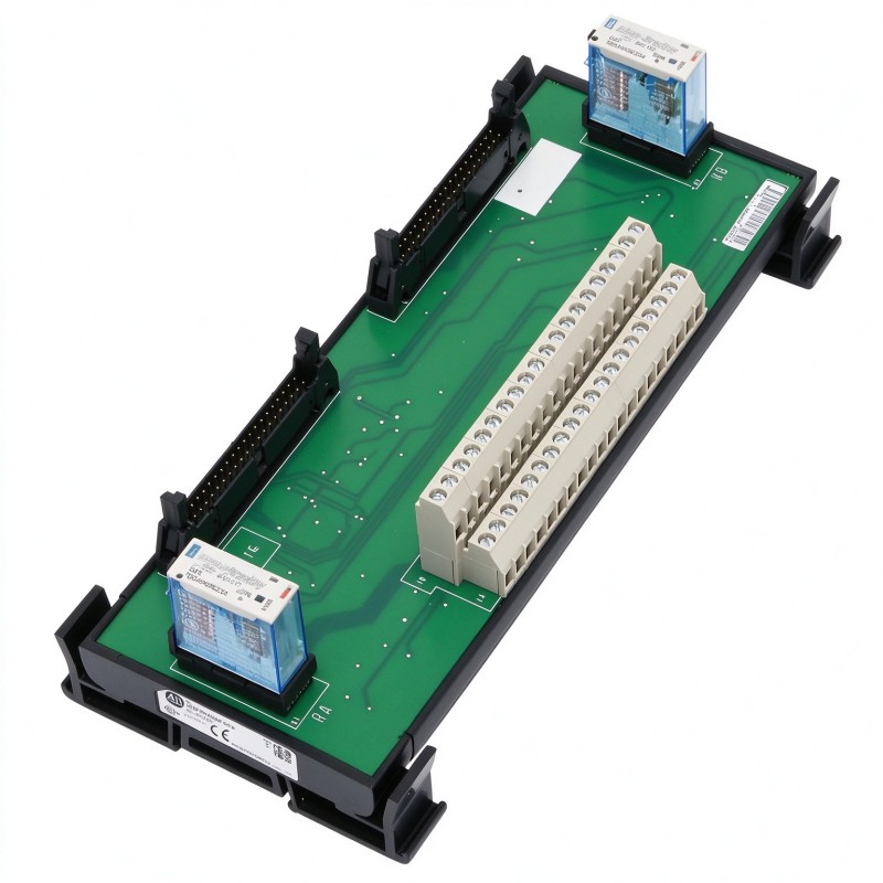
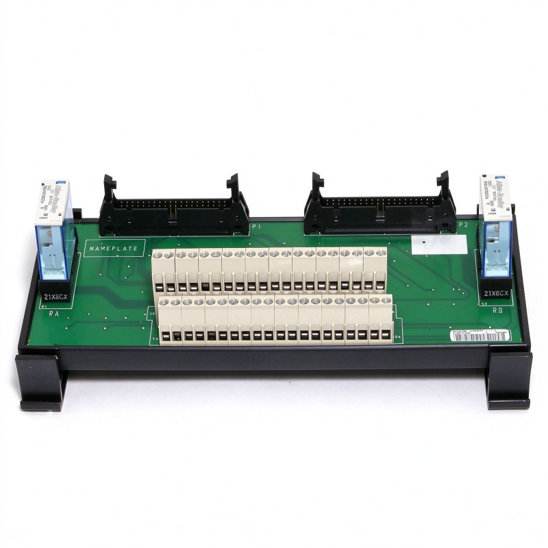
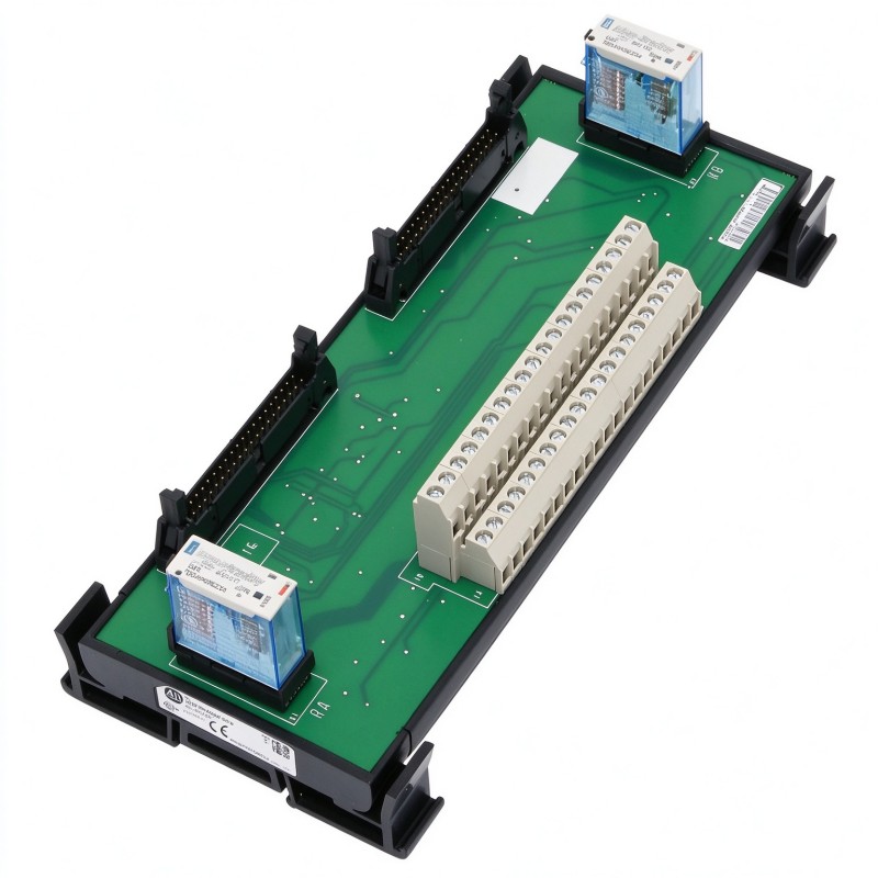
The Allen Bradley 1492-TIFM40F-24-2 Termination Module is a specialized wiring interface for ControlLogix safety shutdown applications using two 1756-OB16D DC diagnostic output modules. Rather than serving as a general-purpose terminal block, it combines field-wiring connections with relay-based control of the output modules’ power supply. This arrangement supports applications in which the power feeding the two output modules must be interrupted separately.
In a typical industrial installation, a ControlLogix controller sends discrete output commands to devices such as solenoid valves, contactor control circuits, and other machine actuators. The 1492-TIFM40F-24-2 organizes the connections between the controller’s output modules and the field wiring. Its internal relay arrangement allows the supply to each output module to be controlled independently, providing a defined mechanism for removing output power as part of the safety shutdown architecture.
The module is intended specifically for a SIL 2 safety shutdown configuration using two 1756-OB16D output modules. The two output modules and their associated wiring must be arranged according to the applicable safety design. The termination module alone does not establish a SIL 2 safety function; the overall architecture, controller configuration, wiring, field devices, and validation procedures determine whether the completed application meets its required safety integrity level.
One practical advantage of this arrangement is that it combines the output wiring and power-interruption relay connections in a dedicated interface. Instead of building the entire termination arrangement from individual terminal blocks and separate relay assemblies, the panel builder can use the module’s defined terminal layout and compatible prewired cables. This helps keep the output wiring organized in cabinets containing multiple safety-related circuits.
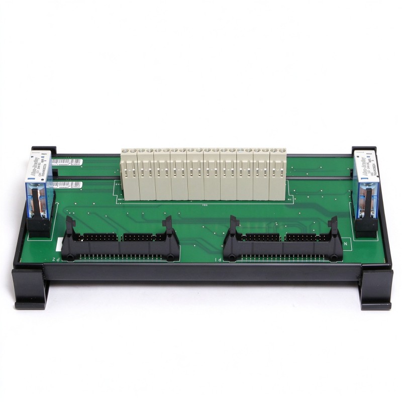
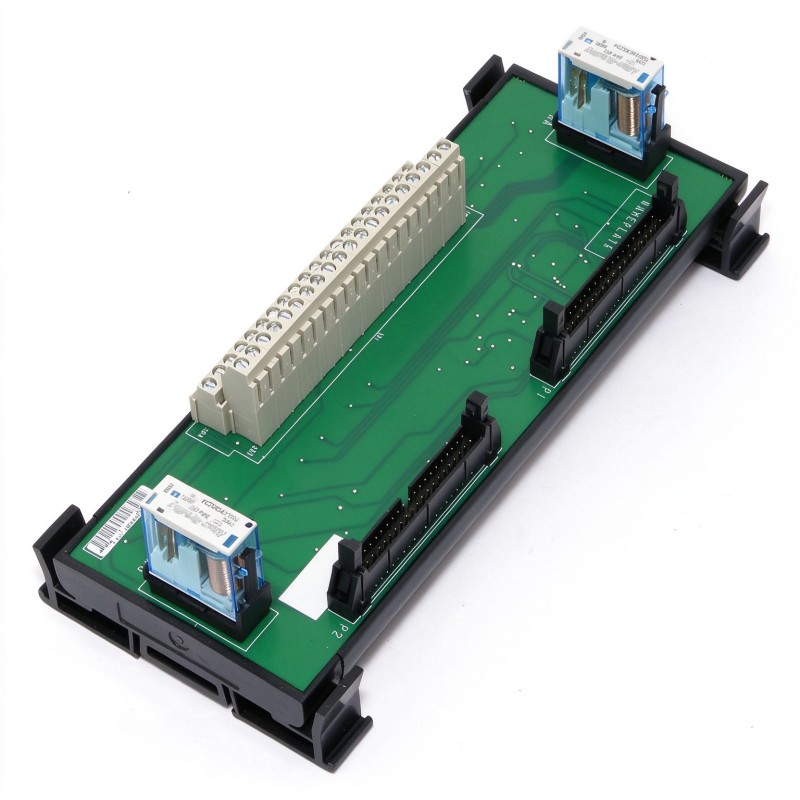
The 1492-TIFM40F-24-2 uses two 40-pin cable connections for interfacing with the two 1756-OB16D modules. Field-side connections are arranged across terminal rows identified as A and B. The associated wiring diagrams identify the output channels, common connections, DC supply connections, and relay-control terminals. Correct terminal assignment is essential because the interface must preserve the intended relationship between each output module, its field circuits, and its power-interruption relay.
The module also has defined electrical loading limits. Its published ratings specify a maximum of 1.5 A per circuit and 6 A per module. These limits must be considered alongside the load characteristics of the connected devices and the applicable wiring-system requirements. A circuit that exceeds the permitted current can cause overheating or damage, while an incorrectly wired inductive load can generate voltage transients that affect connected equipment.
For maintenance engineers, the important distinction is between an ordinary output wiring fault and a power-interruption or safety-architecture fault. A field device that fails to respond may be affected by the output channel, the external supply, the relay-control circuit, the cable connection, or the field wiring. Troubleshooting should therefore follow the documented circuit arrangement rather than treating the termination module as an interchangeable passive terminal strip.
Technical Specifications
| Parameter | Specification |
|---|---|
| Manufacturer | Allen-Bradley |
| Model | 1492-TIFM40F-24-2 |
| Product Type | Termination Module for SIL 2 Safety Shutdown Applications |
| Product Family | Bulletin 1492 Connection Products |
| Compatible Controller Platform | ControlLogix Bulletin 1756 I/O |
| Intended Output Modules | Two 1756-OB16D DC Diagnostic Output Modules |
| Primary Function | Output signal termination and relay-based power interruption |
| Application Category | SIL 2 Safety Shutdown System |
| Cable Connector Type | 40-pin |
| Cable Interface | Two module connections |
| Interface Style | Feed-through |
| Relay Arrangement | Two power-interruption relays |
| Relay Control | Separate 24V DC PLC outputs |
| Supply Voltage | 24V DC control supply for relay operation |
| Maximum Current per Circuit | 1.5 A |
| Maximum Current per Module | 6 A |
| Maximum Recurring Peak Voltage | 100 Vp |
| Operating Temperature | 0–60°C |
| Operating Humidity | 5–95% |
| Required Cable Arrangement | Two compatible cables for the two output modules |
| Dimensions | 130 mm × 50 mm × 58 mm |
| Weight | 0.21 kg |
Product Features
- Dedicated SIL 2 shutdown application: Intended for a ControlLogix arrangement using two 1756-OB16D output modules.
- Separate output power interruption: Incorporates two relays to interrupt the supply to the individual output modules independently.
- 40-pin module interfaces: Connects the two output modules through their corresponding cable assemblies.
- Organized field termination: Provides designated terminals for output signals, DC supply connections, and common conductors.
- Defined relay-control arrangement: Uses separate 24V DC PLC outputs to control the power-interruption relays.
- Specified circuit loading: Supports a maximum of 1.5 A per circuit and 6 A per module within the applicable ratings.
- Panel wiring integration: Combines termination and relay-related connections in a dedicated interface assembly.
- Documented connection layout: Uses identified terminal rows and pin assignments to support structured installation and troubleshooting.
Working Principle
The 1492-TIFM40F-24-2 works as an interface between two ControlLogix 1756-OB16D output modules and their associated field circuits. It routes the output signals through the termination arrangement while incorporating relays that control the power supplied to the individual output modules.
ControlLogix Output Modules → Compatible 40-Pin Cables → Termination Module → Field Wiring and Loads
Two separate 1756-OB16D modules connect to the termination module through compatible cables. The module’s terminal layout provides the corresponding output connections and supply terminals. A separate 24V DC PLC output controls each power-interruption relay, allowing the supply to the two output modules to be removed individually.
Consider an automated process in which a controller operates several groups of actuators. During normal operation, the output modules switch the assigned field circuits according to the control program. If the safety shutdown sequence requires output power to be removed, the designated control outputs operate the relevant relays. The relays interrupt the supply to their respective output modules, preventing those modules from continuing to energize field outputs through that supply path.
This arrangement is different from simply issuing an OFF command to a digital output. A software command changes the requested output state, whereas interrupting the output module’s supply provides a separate means of removing the energy available to the output circuits. The effectiveness of the complete safety function still depends on the approved system architecture and the behavior of the connected field devices.
The termination module does not independently assess hazardous conditions or decide when a machine should stop. Those functions belong to the configured safety control system and its associated devices. The module provides the wiring and relay interface used within that architecture.
Correct wiring is essential to the intended operation. The two output modules must be connected to their designated cable interfaces, and the relay-control circuits must use the specified 24V DC control outputs. The output channels, common conductors, and supply connections must follow the applicable wiring diagram. Incorrect connections can prevent the expected shutdown behavior or cause the wrong circuit to lose power.
The module’s current limits also apply throughout operation. Each field circuit must remain within the permitted rating, and the combined load on the interface must not exceed its module-level limit. Inductive loads require appropriate suppression where specified by the circuit design, since switching transients can damage components or interfere with connected electronics.
Role in a ControlLogix Safety Shutdown Architecture
The 1492-TIFM40F-24-2 occupies the wiring and power-interruption layer between the ControlLogix output modules and the field devices. It does not replace the controller, the safety logic, or the external equipment that performs the required shutdown action.
Safety Control Logic → Output and Relay-Control Signals → Termination Interface → Field Circuits
| System Component | Function |
|---|---|
| Allen-Bradley 1492-TIFM40F-24-2 | Terminates the output wiring and provides relay-based interruption of module power |
| 1756-OB16D Module A | Handles its assigned group of DC output signals |
| 1756-OB16D Module B | Handles the second group of DC output signals |
| Compatible 40-Pin Cables | Connect each output module to its corresponding termination interface |
| 24V DC Relay-Control Outputs | Control the two power-interruption relays |
| External DC Supply | Supplies the output circuits according to the system wiring arrangement |
| Field Terminal Connections | Connect the interface to the associated field circuits |
| Solenoid Valves or Contactors | Perform the commanded field action where used |
| Safety Controller and Logic | Determine and execute the required safety response |
| Protective Devices | Provide the required circuit protection for the installation |
The complete safety function must be assessed as a system. The termination module’s intended application does not, by itself, certify the assembled machine or establish its achieved safety integrity level.
Industrial Applications
| Application | Typical Use |
|---|---|
| Process Plant Shutdown Systems | Organizing output wiring and supply interruption for designated shutdown circuits |
| Chemical Processing | Connecting compatible output modules to field devices within a documented safety architecture |
| Oil and Gas Facilities | Supporting specified output power-interruption arrangements in control cabinets |
| Industrial Burner Systems | Providing termination interfaces for designated shutdown-related outputs where the system design permits |
| Automated Production Lines | Connecting groups of output circuits that require a defined power-removal arrangement |
| Material Handling Systems | Organizing output connections for selected actuators and shutdown-related circuits |
| Packaging Machinery | Integrating output termination and power interruption into a compatible ControlLogix panel |
| Industrial Utilities | Supporting designated output circuits in process equipment control cabinets |
| Manufacturing Safety Panels | Separating field termination from the controller’s module-side connections |
| Control System Retrofits | Replacing a documented termination arrangement while retaining the specified output-module architecture |
The appropriate application is determined by the safety design, not simply by whether the field device is connected to a digital output. The module must be used with the specified output-module arrangement and the applicable safety requirements.
Installation and Maintenance
- Confirm the application architecture: Verify that the intended system uses two 1756-OB16D output modules in the documented safety shutdown arrangement.
- Review the wiring diagram: Identify the module-side connections, terminal rows, relay-control terminals, output channels, and supply connections before wiring begins.
- Isolate electrical power: Follow the plant’s lockout/tagout and electrical safety procedures before installing or servicing the interface.
- Inspect the module: Check the terminal blocks, connector interfaces, mounting points, and enclosure condition for damage.
- Install the module securely: Mount the termination module in the control cabinet using the installation method specified for the assembly.
- Connect both output modules: Use the appropriate compatible cables and connect each 1756-OB16D module to its designated interface.
- Wire the relay-control circuits: Connect the separate 24V DC PLC control outputs to the corresponding power-interruption relay circuits.
- Terminate the field wiring: Connect the output conductors, supply connections, and common conductors according to the documented terminal assignments.
- Check circuit loading: Confirm that no circuit exceeds 1.5 A and that the total current through the interface remains within the 6 A module limit.
- Inspect inductive-load protection: Where relay or output circuits switch inductive loads, confirm that the specified surge-suppression arrangements are installed.
- Perform controlled functional testing: Verify each output channel and each power-interruption relay independently, following the approved commissioning and safety-validation procedure.
- Record inspection results: Document the cable connections, terminal assignments, measured circuit conditions, relay operation, and results of the required safety tests.
If a shutdown test fails, inspect the relay-control signals, external supply, cable connections, output-module status, and field wiring. Do not assume that a normal controller output indication proves that the field circuit has been de-energized. The actual power-interruption behavior must be verified as required by the system’s safety procedures.
Related Components
| Component | Function |
|---|---|
| Allen-Bradley 1492-TIFM40F-24-2 | Termination and power-interruption interface for the specified shutdown arrangement |
| Allen-Bradley 1756-OB16D | ControlLogix 16-point DC diagnostic output module |
| Compatible 1492-CABLE Assembly | Connects the output module to the termination interface |
| 24V DC Control Supply | Supplies the relay-control circuit |
| External Output Power Supply | Supplies the field output circuits according to the wiring design |
| ControlLogix Controller | Executes the configured control and shutdown logic |
| Field Terminal Wiring | Connects output channels to the associated loads |
| Inductive-Load Suppression Components | Limit switching transients where required |
| Circuit Protection Devices | Protect the associated power and field circuits |
| Safety-Related Field Devices | Perform the required shutdown action as defined by the application |
Recommended Related Models
| Model | Product Type | Typical Application |
|---|---|---|
| Allen-Bradley 1492-TIFM40F-24-2 | SIL 2 Safety Shutdown Termination Module | Connecting two 1756-OB16D output modules in the specified shutdown arrangement |
| Allen-Bradley 1756-OB16D | ControlLogix DC Diagnostic Output Module | Providing 16-point DC output control for the compatible interface |
| Allen-Bradley 1756-OB16E | ControlLogix DC Output Module | General-purpose DC output applications where supported by the selected wiring design |
| Allen-Bradley 1756-A7 | ControlLogix Seven-Slot Chassis | Housing compatible ControlLogix controllers and I/O modules |
| Allen-Bradley 1756-PA75 | ControlLogix AC Power Supply | Supplying chassis backplane power in a compatible ControlLogix system |
Key Advantages
- Combines output termination with two separate power-interruption relays.
- Supports the documented ControlLogix SIL 2 shutdown arrangement using two 1756-OB16D modules.
- Provides designated interfaces for module cables, field wiring, and relay-control signals.
- Establishes clear circuit-level and module-level current limits.
- Simplifies wiring organization within compatible industrial control cabinets.
- Supports structured inspection and functional testing of output power-interruption circuits.
Technical FAQs
Why does the 1492-TIFM40F-24-2 use two power-interruption relays?
The module is intended for a configuration with two 1756-OB16D output modules. Its two relays allow the power supplied to each output module to be interrupted separately. This provides the intended power-control arrangement for the documented shutdown architecture rather than relying solely on software output commands.
Which output modules are specified for this termination module?
The specified application uses two Allen-Bradley 1756-OB16D ControlLogix DC diagnostic output modules. The module and cable arrangement should follow the relevant wiring documentation. Substituting a different output module requires a separate compatibility assessment.
What are the maximum current ratings of the 1492-TIFM40F-24-2?
The published limits are 1.5 A per circuit and 6 A per module. Both ratings must be observed. The selected field loads, supply arrangement, conductors, and protective devices must also comply with the applicable electrical requirements.
Does using this termination module automatically make a machine SIL 2 compliant?
No. The module is intended for a SIL 2 safety shutdown application, but the achieved safety integrity level depends on the complete safety-related control system. The controller architecture, configuration, wiring, field devices, diagnostic coverage, validation, and applicable safety requirements must all be addressed.