

ProductPRODUCT
Featured products
Contact Us
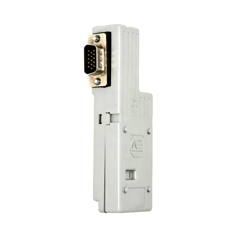
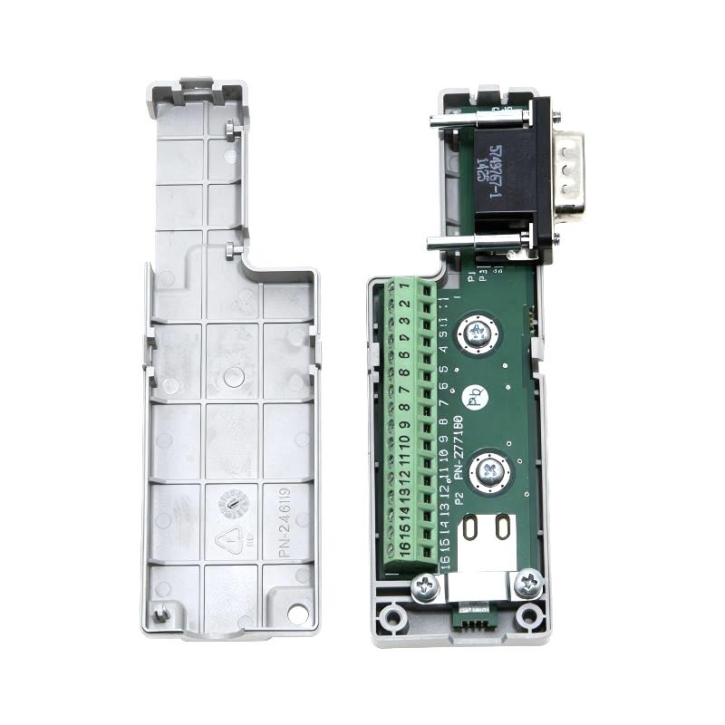
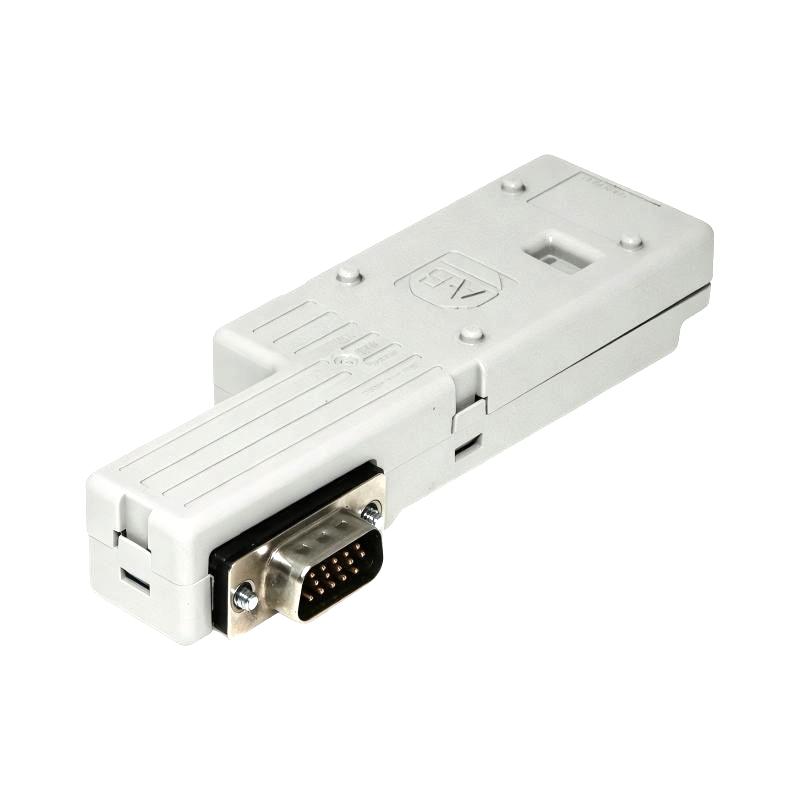
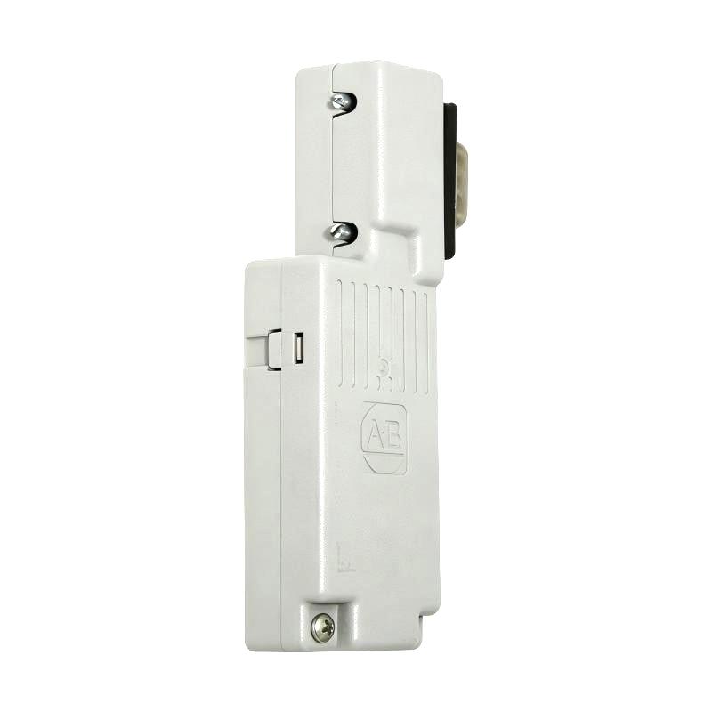
- Allen Bradley
- 2198-K57CK-D15M
- Kinetix 5700 Feedback Connector Kit
- USA
- 92 × 32 × 24 mm
- 0.07 kg
- Xiamen, China
- New & In Stock
- T/T, PayPal, Western Union
- 1 Year
- 1-3 Working Days
- DHL, UPS, TNT, FedEx and EMS.
- 24-Hour Service
- COO
- 5
Our advantage

Global Logistics
We have a 10-year logistics and express cooperation agreement, so our products can be shipped to any place in the world.

Brand new and original
Our products are imported in bulk from the place of origin. Because of the cooperative relationship, our products are all original and 100% new.

24-hour service
We provide 7*24 hours service to our customers. We will be there whenever you need us.

Price advantage
All our products are priced very favorably because we have our own warehouse and supply.
| Company Information | |||
| [email protected] | |||
| Mobile | +8615980777398 | ||
| +8615980777398 | |||
| 15980777398 |
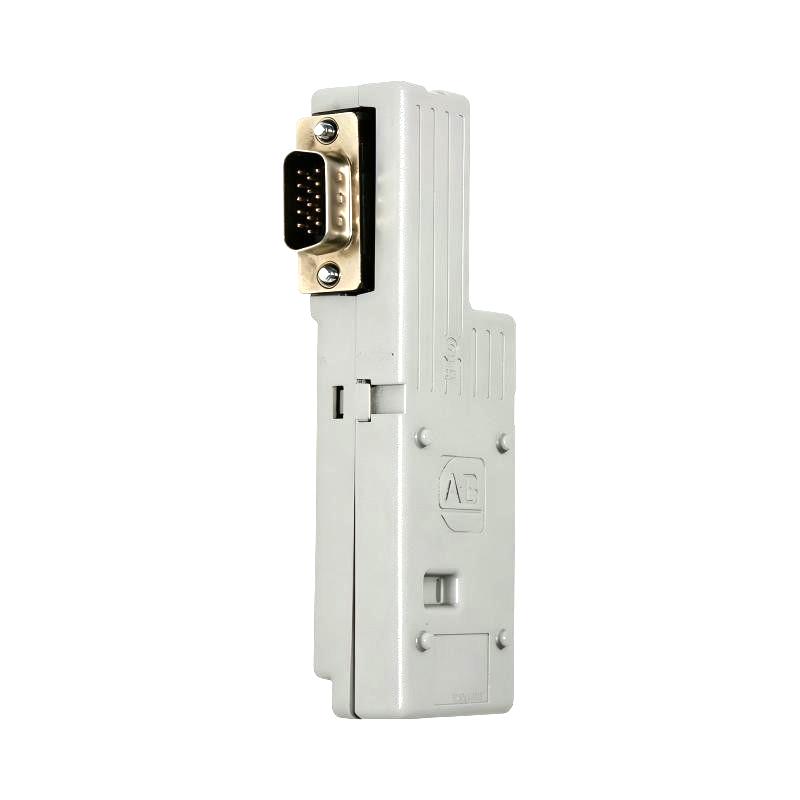
Product Overview
The Allen Bradley 2198-K57CK-D15M Kinetix 5700 Feedback Connector Kit is a universal feedback connection accessory for Kinetix 5700 servo drive systems. It provides the termination arrangement needed to connect compatible encoder signals carried by Allen-Bradley 2090-Series feedback cables to the drive’s 15-pin Universal Feedback (UFB) connector.
In a servo-controlled machine, the drive depends on feedback from an encoder to determine motor position and support accurate motion control. The encoder may use absolute, incremental, or EnDat feedback technology, depending on the motor and application. The 2198-K57CK-D15M provides the electrical connection between the prepared feedback cable conductors and the drive interface, allowing supported feedback signals to reach the control electronics.
This kit is particularly useful in multi-axis machinery where several motors require individual feedback connections. Packaging equipment, automated assembly lines, and material-handling systems often use servo axes with different motion profiles. Each feedback cable must be terminated correctly so that the drive receives the intended encoder signals without intermittent connections or electrical interference.
The connector kit accommodates the wiring of feedback conductors to an internal terminal block and provides a defined arrangement for cable-shield termination. The cable must be prepared carefully before installation. Conductor lengths need to allow a suitable service loop, insulation must be stripped to the required length, and the shield drain wire must be connected to the designated terminal. These details affect both connection quality and the feedback circuit’s resistance to electrical noise.
The 2198-K57CK-D15M is also relevant when a compatible Kinetix 5700 drive uses the universal feedback interface for an auxiliary feedback device. In this arrangement, the encoder can provide information for a supported load-position or secondary feedback application, subject to the drive configuration. This differs from the primary motor-feedback arrangement, where the feedback device is used directly for motor control.
The kit does not convert one encoder protocol into another. Compatible feedback signals pass through the connector assembly to the drive. Consequently, the selected encoder, cable, terminal assignments, and drive configuration must match the intended application. A connector that fits mechanically does not make an otherwise unsupported feedback device compatible.
For commissioning engineers, the main considerations are cable preparation, pin assignment, shield termination, and connector engagement. If the drive reports a feedback fault, checking these items alongside encoder compatibility and drive configuration is a practical starting point. Correct termination helps the drive receive usable feedback and reduces avoidable commissioning problems.
Technical Specifications
| Parameter | Specification |
|---|---|
| Manufacturer | Allen-Bradley |
| Model | 2198-K57CK-D15M |
| Product Type | Kinetix 5700 Feedback Connector Kit |
| Product Family | Kinetix 5700 Servo Drive Accessories |
| Accessory Category | Universal Feedback Connector Kit |
| Compatible Drive Family | Kinetix 5700 |
| Drive Feedback Interface | 15-pin Universal Feedback (UFB) |
| Cable Compatibility | Compatible Allen-Bradley 2090-Series feedback cables |
| Supported Feedback Types | Compatible absolute, incremental, and EnDat feedback devices |
| Feedback Application | Motor feedback or supported auxiliary feedback |
| Internal Termination | 16-pin terminal arrangement, including the shield drain connection |
| Cable Shield Termination | Dedicated drain-wire connection at pin 16 |
| Signal Conversion | No protocol conversion; compatible signals pass through to the drive |
| Installation Method | Feedback cable preparation, terminal wiring, and connector mounting |
| Dimensions | 92 × 32 × 24 mm |
| Weight | 0.07 kg |
Product Features
- Universal feedback connection: Connects compatible encoder feedback wiring to the Kinetix 5700 UFB interface.
- Multiple feedback technologies: Supports compatible absolute, incremental, and EnDat feedback devices.
- Defined terminal arrangement: Provides designated connection points for individual feedback conductors.
- Cable-shield termination: Supports the required drain-wire connection for the feedback cable.
- 2090-Series cable integration: Accommodates compatible feedback cables after the required preparation.
- Motor and auxiliary feedback use: Supports the feedback role permitted by the selected drive configuration.
- Service-loop provision: Allows cable conductors to be routed with sufficient length for orderly termination and maintenance.
- Drive-mounted connection: Establishes the feedback interface at the compatible Kinetix 5700 drive.
Working Principle
The 2198-K57CK-D15M establishes an electrical path between a compatible encoder cable and the Kinetix 5700 drive’s Universal Feedback connector. The kit does not interpret position data or calculate motor movement. Those tasks remain with the encoder and drive control electronics.
Encoder → 2090-Series Feedback Cable → 2198-K57CK-D15M → UFB Connector → Kinetix 5700 Drive
The encoder generates feedback signals according to its technology. An absolute encoder supplies position information within its supported measurement range, while an incremental encoder generates signals from which the drive can determine movement. EnDat devices use their corresponding feedback interface. The drive must be configured for a feedback type that it supports.
During installation, the feedback cable is prepared so that its conductors reach the correct terminals without excessive tension. The individual wires are inserted into their assigned positions and secured. The exposed cable shield is positioned under the designated clamp, and the drain wire is connected to pin 16 as specified for this kit. The completed assembly then connects to the drive’s UFB interface.
Consider a machine with a servo motor driving a positioning table. As the motor rotates, the encoder generates feedback that the drive uses to regulate movement. The connector kit carries the encoder signals to the drive, allowing the control system to compare the measured feedback with the commanded motion. The drive then adjusts motor output to follow the requested position or velocity profile.
The same connection principle can apply to a supported auxiliary feedback arrangement. For example, a machine may need to monitor load position separately from motor position. If the selected Kinetix 5700 configuration supports the required auxiliary feedback device, the connector kit can provide the necessary termination path for that encoder.
Signal integrity depends on correct assembly. A conductor placed in the wrong terminal can prevent the drive from interpreting the encoder signals correctly. A loose wire may cause intermittent feedback loss, while improper shield termination can increase susceptibility to electrical interference. The cable should also be routed to avoid unnecessary strain and interference from high-power wiring.
Because the kit is a passive connection accessory, it cannot make an incompatible encoder suitable for the drive. The feedback device and its electrical interface must be supported by the drive, and the wiring must follow the correct pin assignment for that device.
Role in a Kinetix 5700 Servo Feedback System
The 2198-K57CK-D15M provides the termination interface between a compatible feedback cable and the Kinetix 5700 drive. Its role is to maintain the intended signal connections so the drive can receive motor-position or supported auxiliary feedback.
Feedback Device → Feedback Cable → Connector Kit → UFB Interface → Servo Drive Control
| System Component | Function |
|---|---|
| Allen-Bradley 2198-K57CK-D15M | Terminates compatible encoder feedback conductors for the UFB connection |
| Servo Motor Encoder | Generates motor-position or motion-related feedback |
| Auxiliary Encoder, Where Supported | Supplies feedback for a compatible load-position or secondary-feedback application |
| Allen-Bradley 2090-Series Feedback Cable | Carries encoder signals to the connector kit |
| Kinetix 5700 Servo Drive | Processes supported feedback and regulates motor operation |
| UFB Connector | Provides the drive-side universal feedback interface |
| Cable Shield Clamp | Secures the exposed shield in the intended termination position |
| Drain Wire | Establishes the designated shield connection at pin 16 |
| Machine Controller | Coordinates motion commands and machine sequences |
| Mechanical Load | Receives the controlled movement produced by the servo motor |
The feedback device, cable, connector kit, and drive configuration must be compatible as a complete signal path.
Industrial Applications
| Application | Typical Use |
|---|---|
| Packaging Machinery | Connecting encoder feedback for indexing, sealing, cutting, and positioning axes |
| Automated Assembly | Carrying motor feedback signals for coordinated component placement |
| Material Handling | Supporting servo feedback connections in transfer and positioning equipment |
| Machine Tools | Connecting compatible encoder feedback for controlled axis movement |
| Printing and Converting | Maintaining feedback connections for synchronized rollers and web-handling axes |
| Electronic Manufacturing | Connecting supported feedback devices used in precision motion systems |
| Linear Positioning Systems | Carrying feedback signals from compatible motor or actuator encoders |
| Multi-Axis Automation | Providing individual feedback connections for multiple servo-controlled axes |
| Load-Position Monitoring | Supporting auxiliary feedback where permitted by the drive configuration |
| Servo System Retrofits | Terminating compatible existing feedback cables for a Kinetix 5700 installation |
The kit is suitable for applications in which the encoder technology and electrical interface are supported by the selected drive. Feedback wiring must be matched to the device rather than assigned solely by conductor color.
Installation and Maintenance
- Confirm feedback compatibility: Check that the encoder type, feedback cable, and Kinetix 5700 drive support the intended motor or auxiliary feedback arrangement.
- Inspect the connector kit: Examine the connector body, terminal block, shield clamp, and mounting features for damage before installation.
- Prepare the feedback cable: Follow the applicable cable-preparation instructions for jacket removal, shield exposure, conductor length, and insulation stripping.
- Trim the shield carefully: Prevent loose shield strands from contacting adjacent terminals or creating an unintended electrical connection.
- Prepare the drain wire: Ensure the drain wire is available for connection to pin 16. If the cable does not include a separate drain wire, follow the specified procedure for forming one from the overall shield braid.
- Identify the terminal assignments: Use the correct pinout for the encoder and drive configuration instead of relying only on conductor colors.
- Route the conductors: Insert each wire into its assigned terminal and leave sufficient service-loop length for the longest conductors.
- Tighten the terminal screws: Apply the specified terminal torque and check that each conductor is securely retained.
- Secure the cable shield: Position the exposed shield in the designated channel and tighten the shield-clamp screws to the specified torque.
- Provide strain relief: Arrange the cable and service loop so that movement, vibration, or cable tension does not pull on the terminal connections.
- Connect and test the feedback path: Mount the connector kit, engage the UFB connector correctly, and verify that the drive recognizes the configured feedback device during commissioning.
- Document inspection results: Record the encoder type, cable identification, terminal arrangement, and any feedback faults observed during testing.
When a feedback fault occurs, inspect the terminal wiring, shield connection, connector seating, and cable condition before replacing the kit. Also confirm that the drive is configured for the installed encoder type.
Related Components
| Component | Function |
|---|---|
| Allen-Bradley 2198-K57CK-D15M | Universal feedback connector kit for compatible Kinetix 5700 drives |
| Allen-Bradley Kinetix 5700 Servo Drive | Processes supported motor or auxiliary feedback |
| Allen-Bradley 2090-Series Feedback Cable | Carries encoder signals to the connector kit |
| Compatible Hiperface Encoder | Supplies supported absolute position feedback through the UFB interface |
| Compatible Incremental Encoder | Supplies incremental feedback signals supported by the drive |
| Compatible EnDat Encoder | Provides feedback through a supported EnDat interface |
| Cable Shield Clamp | Secures the exposed feedback-cable shield |
| Feedback Cable Drain Wire | Connects the cable shield to the designated terminal |
| Machine Controller | Coordinates the servo axis with the overall machine sequence |
| Servo Motor | Produces controlled mechanical movement based on drive commands |
Recommended Related Models
| Model / Product Reference | Product Type | Typical Application |
|---|---|---|
| Allen-Bradley 2198-K57CK-D15M | Kinetix 5700 Feedback Connector Kit | Terminating compatible encoder feedback for the UFB interface |
| Allen-Bradley 2198-H2DCK | Hiperface-to-DSL Feedback Converter Kit | Converting compatible Hiperface feedback to DSL for the motor-feedback interface |
| Allen-Bradley 2198-S086-ERS | Kinetix 5700 Single-Axis Inverter | Controlling one compatible servo motor axis |
| Allen-Bradley 2198-D006-ERS | Kinetix 5700 Dual-Axis Inverter | Controlling two compatible servo motor axes |
| Allen-Bradley 2198-P031 | Kinetix 5700 DC-Bus Power Supply | Supplying DC-bus power in a compatible servo system |
Key Advantages
- Establishes a defined feedback connection to the Kinetix 5700 UFB interface.
- Supports compatible absolute, incremental, and EnDat feedback devices.
- Accommodates compatible Allen-Bradley 2090-Series feedback cables.
- Provides a designated terminal for the feedback cable drain wire.
- Supports motor or auxiliary feedback applications where the drive configuration permits.
- Helps organize feedback wiring for commissioning and maintenance.
Technical FAQs
How does the 2198-K57CK-D15M differ from the 2198-H2DCK?
The 2198-K57CK-D15M is a universal feedback connector kit through which compatible encoder signals pass to the drive. The 2198-H2DCK performs a specific conversion from 15-pin Hiperface feedback to the two-pin DSL interface. They serve different feedback connection arrangements and are not interchangeable in every installation.
Which feedback technologies can be used with the 2198-K57CK-D15M?
The Kinetix 5700 UFB interface supports compatible single-turn and multi-turn absolute feedback, incremental feedback, and EnDat feedback technologies. The exact encoder type and electrical interface must be supported by the selected drive and its configuration.
Why must the feedback cable drain wire connect to pin 16?
The drain-wire connection establishes the specified shield termination for the feedback cable. Correct shield bonding helps control electrical interference in a servo installation. If the cable does not contain a separate drain wire, the installation instructions specify how to form one from the overall shield braid.
Can this connector kit be used for auxiliary feedback instead of motor feedback?
Yes, where the selected Kinetix 5700 drive and feedback configuration support auxiliary feedback. The kit provides the physical termination interface, but the encoder type, signal assignment, and drive setup must all be appropriate for the intended auxiliary-feedback function.