

ProductPRODUCT
Featured products
Contact Us
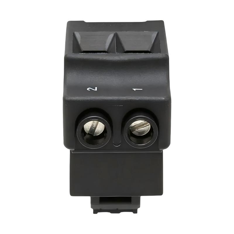
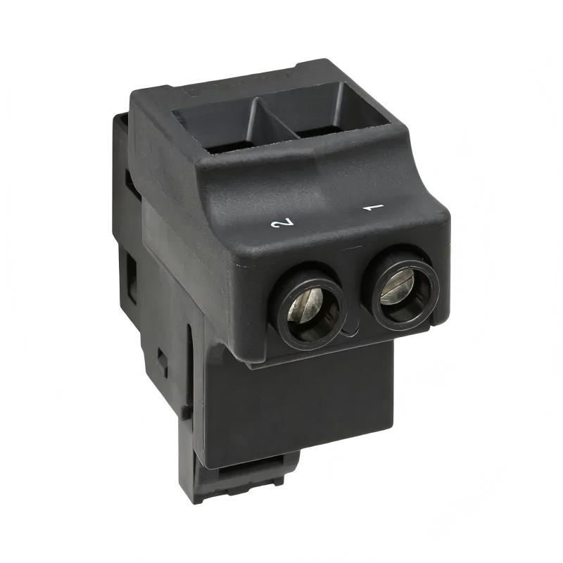
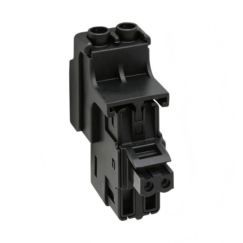
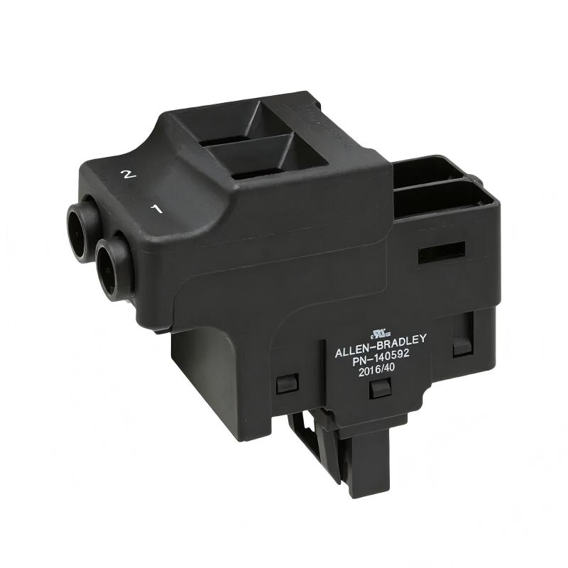
- Allen Bradley
- 2198-TCON-24VDCIN36
- Kinetix 5500/5700 DC Input Connector
- USA
- 82 × 30 × 46 mm
- Xiamen, China
- New & In Stock
- T/T, PayPal, Western Union
- 1 Year
- 1-3 Working Days
- DHL, UPS, TNT, FedEx and EMS.
- 24-Hour Service
- COO
- 5
Our advantage

Global Logistics
We have a 10-year logistics and express cooperation agreement, so our products can be shipped to any place in the world.

Brand new and original
Our products are imported in bulk from the place of origin. Because of the cooperative relationship, our products are all original and 100% new.

24-hour service
We provide 7*24 hours service to our customers. We will be there whenever you need us.

Price advantage
All our products are priced very favorably because we have our own warehouse and supply.
| Company Information | |||
| [email protected] | |||
| Mobile | +8615980777398 | ||
| +8615980777398 | |||
| 15980777398 |
Product Overview
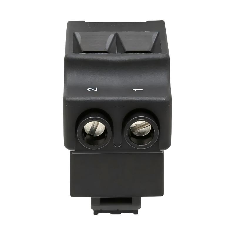
The Allen Bradley 2198-TCON-24VDCIN36 Kinetix 5500/5700 DC Input Connector is an electrical connection accessory used to introduce 24V DC control power into a shared-bus servo drive arrangement. It belongs to the Bulletin 2198 accessory range and is used with compatible Kinetix 5500 and Kinetix 5700 drive systems.
In a multi-axis machine, several servo drives may operate from a common control system while requiring a coordinated 24V DC supply for their control electronics. Rather than routing an independent control-power connection to every module, a shared control-power arrangement allows the supply to enter the drive cluster through an input connector and continue through compatible T-connectors and bus bars. This reduces wiring complexity and gives the cabinet a more organized power distribution layout.
The 2198-TCON-24VDCIN36 serves as the entry point for the 24V DC control-power connection system. It accepts the incoming control-power wiring and provides the interface needed to extend the supply through compatible modules. In a machine with multiple servo axes, this arrangement can simplify panel wiring and make the control-power distribution easier to inspect during commissioning and maintenance.
The connector is intended for control power, not the main motor power circuit. The 24V DC supply supports the control-power requirements of the connected drive system, while the drive’s separate power connections handle the electrical energy used to operate the motors. Keeping these functions distinct is essential when laying out the cabinet and preparing the wiring.
The shared-bus arrangement also has defined installation requirements. The input connector starts the 24V DC connection system, while compatible T-connectors and bus bars extend it across the drive cluster. The connection must be arranged in the correct direction, and the total control-power current must remain within the system’s permitted rating. The documented maximum current for this connection system is 40 A.
For maintenance engineers, the main concerns are secure wiring, correct polarity, connector seating, bus-bar alignment, and the total load placed on the 24V DC supply. A loose connection or incorrectly assembled shared-bus section can affect several drive modules rather than a single axis. Inspecting the entire control-power distribution path is therefore important when multiple drives report control-power-related faults.
Technical Specifications
| Parameter | Specification |
|---|---|
| Manufacturer | Allen-Bradley |
| Model | 2198-TCON-24VDCIN36 |
| Product Type | Kinetix 5500/5700 DC Input Connector |
| Product Family | Bulletin 2198 Kinetix Servo Drive Accessories |
| Accessory Category | 24V DC Control Power Connector Kit |
| Primary Function | Introduces 24V DC control power into a shared-bus connection system |
| Rated Supply Voltage | 24V DC |
| Compatible Drive Families | Kinetix 5500 and Kinetix 5700 |
| Connection Arrangement | Shared control-power bus |
| System Components | Input wiring connector, compatible T-connectors, and bus bars |
| Maximum Shared Control-Power Current | 40 A |
| Installation Direction | Control-power bus extends from left to right |
| Input Wiring | Customer-supplied 24V DC control-power wiring |
| Main Power Function | Not intended as the main motor-power or DC-bus power connector |
| Dimensions | 82 × 30 × 46 mm |
| Weight | 0.085 kg |
Product Features
- 24V DC control-power input: Provides the entry point for the control-power supply in a compatible shared-bus arrangement.
- Kinetix 5500/5700 compatibility: Supports the specified servo drive families using the Bulletin 2198 shared connection system.
- Shared-bus distribution: Allows control power to extend across compatible modules without separate incoming wiring at every connection point.
- Expandable connection arrangement: Works with compatible T-connectors and bus bars to distribute control power across a drive cluster.
- Defined current limit: The shared control-power connection system has a documented maximum current rating of 40 A.
- Organized cabinet wiring: Helps structure control-power distribution in multi-axis servo installations.
- Modular installation: Allows the control-power connection system to be assembled according to the drive cluster layout.
- Serviceable connection path: Provides identifiable connection points for inspection and troubleshooting.
Working Principle
The 2198-TCON-24VDCIN36 introduces the incoming 24V DC control supply into the shared control-power connection system. Once installed, compatible bus components carry that supply along the drive cluster, allowing the connected modules to receive control power through the intended distribution arrangement.
24V DC Supply → 2198-TCON-24VDCIN36 → Shared-Bus Connectors → Compatible Drive Modules
During installation, the incoming positive and common conductors are connected to the designated terminals. The input connector is then installed in the appropriate position within the drive cluster. Compatible T-connectors and bus bars extend the control-power connection to the downstream modules.
For example, a packaging machine may use several Kinetix servo drives to control separate conveyor, indexing, and positioning axes. The 24V DC supply enters the control-power bus through the 2198-TCON-24VDCIN36. The shared-bus components then distribute the supply through the connected drive arrangement, reducing the need for individual incoming control-power connections at each module.
The direction of the connection system matters. The 24V DC bus must extend from left to right through the designated connector arrangement. If the input connector is installed incorrectly or a bus-bar connection is not fully engaged, the control-power distribution may not operate as intended. Correct placement and secure engagement should be confirmed before the system is energized.
Current capacity must also be considered when designing the control-power distribution. The shared connection system has a maximum rating of 40 A. If the combined control-power demand reaches the permitted limit, the documented system arrangement allows another compatible input wiring connector to establish an additional 24V control-power entry point. The supply design and wiring must still comply with the requirements of the selected equipment.
The connector does not regulate the 24V DC supply or convert it into motor power. Its role is to establish the electrical connection through which the control supply enters the shared-bus system. The upstream supply remains responsible for delivering the correct voltage and sufficient current, while the drive modules use the distributed power for their control functions.
Role in a Kinetix 5500/5700 Shared Control-Power System
The 2198-TCON-24VDCIN36 serves as the control-power entry component in a shared-bus drive arrangement. It connects the incoming 24V DC supply to the distribution components that extend control power across compatible servo drive modules.
24V DC Control Supply → Input Connector → T-Connectors and Bus Bars → Servo Drive Modules
| System Component | Function |
|---|---|
| Allen-Bradley 2198-TCON-24VDCIN36 | Introduces incoming 24V DC control power into the shared-bus system |
| 24V DC Power Supply | Provides the control voltage required by the connected equipment |
| Kinetix 5500 Servo Drive | Uses the distributed control power for its control functions |
| Kinetix 5700 Servo Drive | Receives control power through the compatible shared-bus arrangement |
| 24V DC T-Connector | Extends the control-power connection to a downstream module |
| Shared-Bus Bar | Carries control power between compatible connector assemblies |
| Electrical Protection | Protects the control-power circuit according to the installation design |
| Control Cabinet Wiring | Connects the supply and shared-bus components |
| Machine Controller | Coordinates the motion sequence and exchanges commands and status with the drive system |
The shared control-power connection is separate from the main power and DC-bus connections used by the drive system. Each circuit must be wired according to its designated connection points and electrical requirements.
Industrial Applications
| Application | Typical Use |
|---|---|
| Multi-Axis Servo Machines | Distributing 24V DC control power across a group of servo drives |
| Packaging Lines | Supplying control power to drive modules serving multiple machine axes |
| Automated Assembly Equipment | Organizing control-power connections in coordinated positioning systems |
| Material Handling Systems | Supporting shared control-power distribution in conveyor and transfer equipment |
| Industrial Robotics Equipment | Providing a control-power entry point in compatible servo drive installations |
| Machine Tools | Extending control power through a multi-module servo drive cluster |
| Automated Inspection Systems | Supporting control-power distribution for coordinated motion axes |
| Printing Machinery | Organizing control wiring across multiple servo-controlled sections |
| Centralized Servo Cabinets | Reducing individual incoming control-power connections across compatible modules |
| Custom Automation Systems | Building a modular 24V DC control-power distribution arrangement |
The connector is most useful in installations where compatible drive modules share a 24V DC control-power distribution system. Its selection must account for the drive family, bus arrangement, supply capacity, and overall control-power demand.
Installation and Maintenance
- Confirm the connector application: Verify that the 2198-TCON-24VDCIN36 matches the intended Kinetix 5500 or Kinetix 5700 shared control-power arrangement.
- Check the 24V DC supply: Confirm that the supply voltage and available current meet the requirements of the connected modules.
- De-energize the system: Isolate the relevant electrical supplies and follow the applicable safety procedures before installing or servicing the connector.
- Identify the correct terminals: Connect the incoming 24V DC positive and common conductors to their designated terminals, observing the required polarity.
- Prepare the conductors: Use suitable wire preparation and termination methods to avoid loose strands, damaged insulation, or poor electrical contact.
- Position the input connector: Install the connector at the intended entry point in the shared control-power arrangement.
- Follow the required bus direction: Arrange the control-power connection system so that it extends from left to right through the designated components.
- Install compatible T-connectors and bus bars: Confirm that the correct connector types are used and that all interfaces are properly engaged.
- Check the total current demand: Keep the shared control-power system within its 40 A maximum rating and provide an additional approved input point where the system design requires it.
- Inspect the connection assembly: Check terminal security, connector seating, bus-bar alignment, and any visible signs of damage before applying power.
- Verify control-power distribution: After completing the required checks, energize the system according to the commissioning procedure and confirm that the connected modules receive the expected control power.
- Record maintenance findings: Document supply conditions, connector inspection results, wiring changes, and any control-power faults identified during testing.
If several drive modules lose control power at the same time, inspect the incoming 24V DC supply and shared-bus connection path before investigating each drive individually. A fault at the input connector or a shared connection can affect multiple modules.
Related Components
| Component | Function |
|---|---|
| Allen-Bradley 2198-TCON-24VDCIN36 | Introduces 24V DC control power into the shared-bus system |
| Allen-Bradley 2198-H040-xxx-xx T-Connector Variant | Extends the shared connection system in compatible Kinetix installations |
| Allen-Bradley 2198-H070-xxx-xx T-Connector Variant | Supports the shared connection arrangement for compatible drive configurations |
| Allen-Bradley 2198-BARCON-55DCAC100 | Shared-bus bar for compatible 55 mm connection arrangements |
| Allen-Bradley 2198-BARCON-85DCAC100 | Shared-bus bar for compatible 85 mm connection arrangements |
| Allen-Bradley 2198-BARCON-100DC100 | Shared-bus bar for compatible Kinetix 5700 configurations |
| Kinetix 5500 Servo Drive | Receives control power through the applicable shared-bus arrangement |
| Kinetix 5700 Servo Drive | Uses the compatible control-power connection system |
| 24V DC Control Power Supply | Supplies the control voltage for the drive cluster |
| Control-Power Wiring | Connects the supply to the input connector and associated components |
Recommended Related Models
| Model / Product Reference | Product Type | Typical Application |
|---|---|---|
| Allen-Bradley 2198-TCON-24VDCIN36 | Kinetix 5500/5700 DC Input Connector | Introducing 24V DC control power into a compatible shared-bus system |
| Allen-Bradley 2198-H040-xxx-xx | Kinetix Shared-Bus T-Connector Variant | Extending the shared connection system in compatible drive configurations |
| Allen-Bradley 2198-H070-xxx-xx | Kinetix Shared-Bus T-Connector Variant | Supporting downstream connections in compatible installations |
| Allen-Bradley 2198-BARCON-55DCAC100 | Kinetix 5500/5700 Bus-Bar Kit | Connecting compatible modules using the 55 mm bus-bar arrangement |
| Allen-Bradley 2198-BARCON-85DCAC100 | Kinetix 5500/5700 Bus-Bar Kit | Connecting compatible modules using the 85 mm bus-bar arrangement |
| Allen-Bradley 2198-BARCON-100DC100 | Kinetix 5700 Bus-Bar Kit | Extending the shared-bus connection in compatible 100 mm arrangements |
Key Advantages
- Establishes a defined 24V DC control-power entry point.
- Supports shared control-power distribution across compatible servo drive modules.
- Helps reduce individual incoming control-power wiring connections.
- Works with compatible T-connectors and bus bars.
- Supports modular layouts for multi-axis servo drive cabinets.
- Provides an identifiable connection point for inspection and troubleshooting.
Technical FAQs
What is the difference between the 2198-TCON-24VDCIN36 and a shared DC-bus power connector?
The 2198-TCON-24VDCIN36 is used to introduce 24V DC control power into the shared control-power connection system. A main DC-bus connector carries power for the drive’s power-conversion section. These circuits serve different purposes and must not be treated as interchangeable.
How many drive modules can share one 2198-TCON-24VDCIN36 connection?
The practical number depends on the combined control-power demand and the approved bus arrangement. The shared 24V DC connection system has a maximum current rating of 40 A. The number of connected modules should therefore be determined from their control-power requirements rather than from the physical number of available connector positions alone.
Why must the shared control-power connection extend from left to right?
The connector system uses a defined orientation for its input connector, T-connectors, and bus bars. Following the specified direction ensures that the components engage in the intended arrangement. Incorrect positioning can prevent proper connection or produce an unsuitable distribution layout.
What should be checked if several Kinetix drives lose control power simultaneously?
Start by checking the 24V DC supply, incoming wiring polarity, and the input connector’s terminal connections. Then inspect the shared bus bars and T-connectors for incomplete engagement or damage. A common supply or distribution fault can affect several drive modules at once, so the shared connection path should be checked before treating the problem as multiple independent drive failures.