

ProductPRODUCT
Featured products
Contact Us
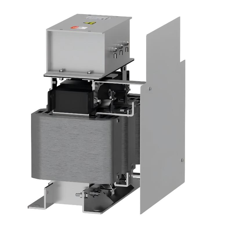
- Schneider
- VW3A5406
- Sine Wave Filter
- France
- 495 x 430 x 350 mm
- 90 kg
- Xiamen, China
- New & In Stock
- T/T, PayPal, Western Union
- 1 Year
- 1-3 Working Days
- DHL, UPS, TNT, FedEx and EMS.
- 24-Hour Service
- COO
- 5
Our advantage

Global Logistics
We have a 10-year logistics and express cooperation agreement, so our products can be shipped to any place in the world.

Brand new and original
Our products are imported in bulk from the place of origin. Because of the cooperative relationship, our products are all original and 100% new.

24-hour service
We provide 7*24 hours service to our customers. We will be there whenever you need us.

Price advantage
All our products are priced very favorably because we have our own warehouse and supply.
| Company Information | |||
| [email protected] | |||
| Mobile | +8615980777398 | ||
| +8615980777398 | |||
| 15980777398 |
1. Product Overview
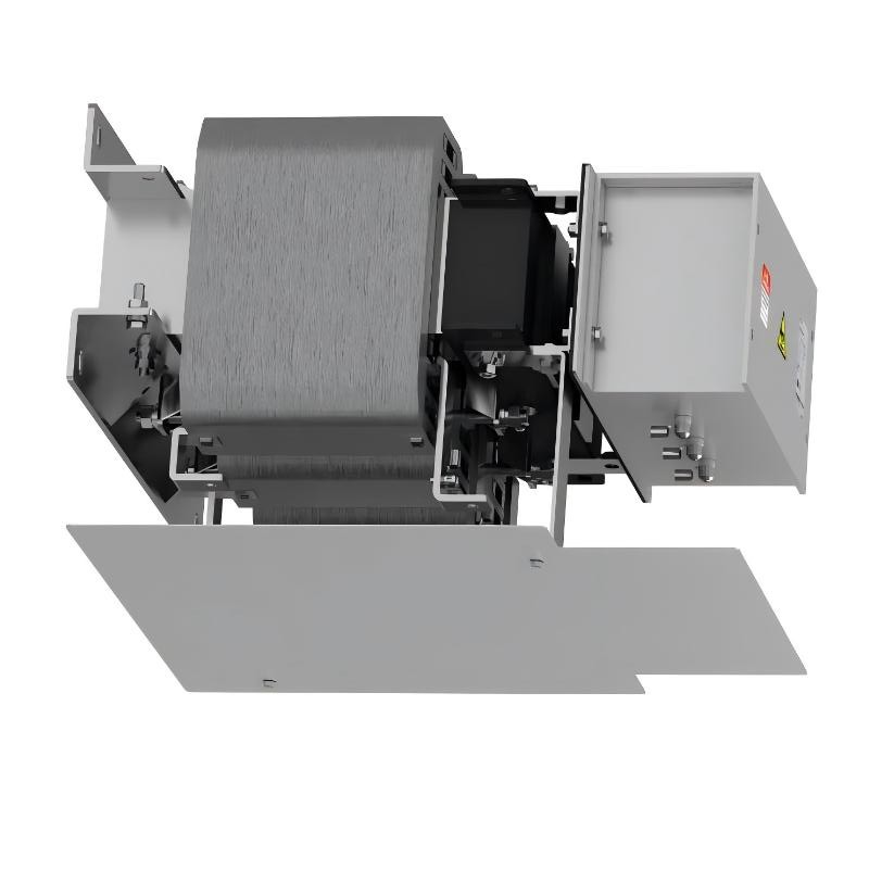
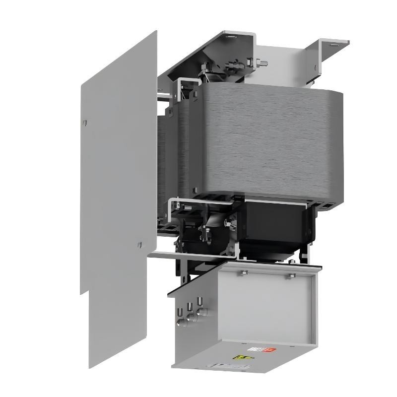
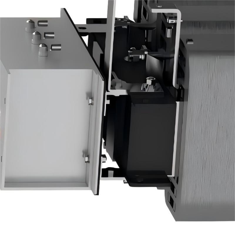
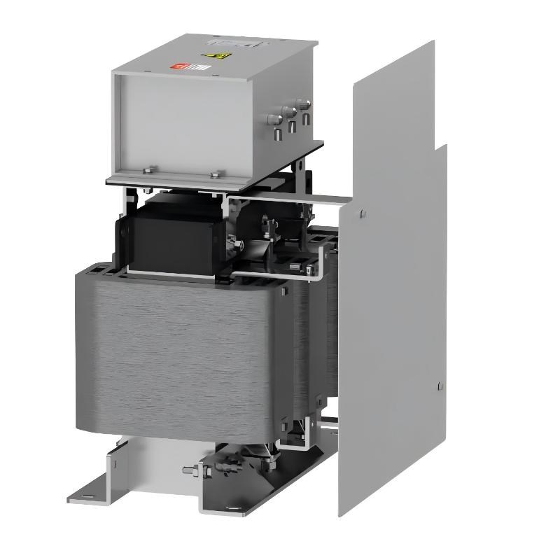
The Schneider Electric VW3A5406 Sine Wave Filter is an industrial drive accessory intended for compatible variable speed drive applications where the output waveform delivered to the motor needs additional filtering. Sine wave filters are used in certain drive installations to reduce the high-frequency components of the inverter output and produce a waveform that more closely resembles a sinusoidal voltage.
Variable frequency drives control motor speed by switching power electronic devices at high frequency. Although this method provides efficient motor control, the resulting output waveform differs from the conventional sinusoidal supply. Depending on the drive, motor, cable arrangement, and application requirements, additional output filtering may be appropriate.
A correctly selected sine wave filter can help reduce motor-terminal voltage distortion and certain high-frequency effects. It may also support applications involving specific motor requirements or longer motor cables, provided the filter and drive manufacturers permit the intended configuration. Actual performance depends on the filter design, switching frequency, load conditions, and electrical characteristics of the complete system.
The Schneider Electric VW3A5406 is listed with dimensions of 495 × 430 × 350 mm and a weight of 90 kg. These specifications are important for installation planning, transportation, lifting arrangements, cabinet layout, and replacement-part management.
Before selecting or installing this filter, confirm its rated voltage, current capacity, supported drive models, permitted operating conditions, and required installation arrangement using the applicable product documentation. A sine wave filter must be matched to the drive and motor system rather than selected by physical size alone.
2. Technical Specifications
| Parameter | Specification |
|---|---|
| Brand | Schneider Electric |
| Model | VW3A5406 |
| Product Type | Sine Wave Filter |
| Product Category | Industrial variable speed drive accessory |
| Dimensions | 495 × 430 × 350 mm |
| Weight | 90 kg |
| Primary Function | Filtering the output waveform of a compatible variable speed drive |
| Typical Installation Position | Between a compatible drive output and motor, subject to manufacturer instructions |
| Rated Voltage | Verify from model-specific documentation |
| Rated Current | Verify from model-specific documentation |
| Filtering Characteristics | Confirm the specified frequency response and output performance |
| Compatible Drive Models | Verify the exact supported drive models |
| Motor Compatibility | Confirm the motor’s electrical and operating requirements |
| Cable Requirements | Verify the permitted motor cable type and length |
| Cooling Requirements | Follow the manufacturer’s installation instructions |
| Mounting Requirements | Provide suitable mechanical support for the 90 kg component |
| Maintenance | Inspect according to operating conditions and site maintenance procedures |
The dimensions and weight above are the supplied product specifications. Electrical ratings and compatibility details should be verified before purchasing, installing, or commissioning the filter.
3. Function and Working Principle
A sine wave filter is designed to reduce selected high-frequency components in the output of a variable speed drive. Its function differs from that of a simple line reactor or a dV/dt filter, so the correct type must be chosen according to the requirements of the application.
3.1 Output Waveform Filtering
A variable speed drive generates its output using high-frequency switching. The resulting pulse-width-modulated waveform contains fundamental-frequency components and higher-frequency components associated with the switching process.
A sine wave filter uses an appropriate filtering network to attenuate selected high-frequency components, allowing the motor to receive a voltage waveform that more closely resembles a sinusoidal waveform. The exact result depends on the filter design and operating conditions.
3.2 Reduction of High-Frequency Voltage Effects
Fast switching transitions and high-frequency components can affect the electrical behavior of the motor circuit. A suitably selected sine wave filter can help reduce certain voltage-related effects at the motor terminals.
The extent of this reduction depends on the drive, filter, motor, cable installation, and operating point. The filter should not be assumed to eliminate all electrical interference or motor insulation stress.
3.3 Motor and Cable Considerations
The motor and cable form part of the overall output circuit. Cable length, cable construction, motor impedance, and drive switching characteristics can affect the performance of the filter.
A sine wave filter may be appropriate for applications with particular motor or cable requirements, but the permitted configuration must be confirmed for the VW3A5406 and the selected drive. Longer cable capability should never be assumed without checking the manufacturer’s specifications.
3.4 Difference Between Sine Wave Filters and dV/dt Filters
A dV/dt filter primarily reduces the rate of voltage change at the motor. A sine wave filter is designed to provide more extensive attenuation of selected high-frequency components so that the motor-terminal waveform more closely approximates a sinusoidal voltage.
The two filter types are not automatically interchangeable. Selection should consider the motor’s requirements, the drive’s output characteristics, cable length, and the intended operating conditions.
4. Role in Industrial Automation Systems
Variable speed drives are widely used in manufacturing, process control, material handling, and other industrial applications. Their performance depends on the correct coordination of the drive, motor, power cables, protective devices, and accessories.
Motor Electrical Performance
A sine wave filter can help modify the electrical waveform delivered to a compatible motor. This may be important in applications where the motor or installation requires reduced high-frequency output components.
Drive-to-Motor Integration
The filter must be selected as part of the complete drive system. The drive rating, switching characteristics, motor requirements, and cable installation all influence whether a particular filter is suitable.
Equipment Reliability
Appropriate output filtering can help manage selected electrical effects, but it does not replace proper grounding, cable selection, motor protection, or correct drive configuration. Reliability depends on the entire installation.
Maintenance and Replacement Planning
Accurate product identification helps maintenance teams select the correct replacement and preserve the intended system configuration. The full model number and relevant electrical ratings should be verified before a replacement is ordered.
5. Industrial Applications
The VW3A5406 may be evaluated for industrial installations that require a compatible sine wave filter. Its suitability depends on the verified electrical ratings and manufacturer-approved drive configuration.
5.1 Manufacturing Machinery
Production lines often use variable speed drives to regulate conveyors, mixers, machine tools, and other motor-driven equipment. Where the motor or electrical design requires additional output filtering, a suitable sine wave filter may form part of the installation.
5.2 Pumps and Fans
Industrial pumping and ventilation systems frequently use variable speed drives to control flow and airflow. Additional output filtering may be appropriate for specific drive-to-motor configurations, subject to the manufacturer’s requirements.
5.3 Material Handling Systems
Conveyors, lifting systems, and automated transport equipment may use motors connected to drives through extended cable runs. A compatible sine wave filter may help manage output waveform characteristics where specified by the system design.
5.4 Process Automation
Process equipment can operate motors continuously or under changing loads. Selecting an appropriate filter requires consideration of the motor’s electrical requirements, the operating duty, and the drive manufacturer’s recommendations.
5.5 Industrial Drive Modernization
When an existing drive is replaced or an automation system is upgraded, engineers should reassess the output filter, motor, and cable arrangement. The VW3A5406 should only be introduced into a modified system after compatibility has been confirmed.
These examples describe general environments in which appropriately selected sine wave filters may be used. They do not establish compatibility of the VW3A5406 with every application listed.
6. Installation and System Integration
Installation should be carried out by qualified personnel in accordance with the applicable Schneider Electric documentation and site electrical safety procedures.
Step 1: Verify the Product Model
Confirm that the product label identifies the component as VW3A5406. Compare the model number with the system drawings, equipment list, and original component where applicable.
Step 2: Isolate the Equipment
Stop the drive and isolate all relevant power sources before installing or removing the filter. Follow the site’s lockout/tagout procedures, observe the specified discharge time, and verify that the equipment is in a safe, de-energized state before handling electrical connections.
Step 3: Confirm Electrical Compatibility
Verify the filter’s rated voltage, rated current, supported drive models, and specified operating conditions. Confirm that the filter is suitable for the intended drive output and motor application.
Do not assume that a filter is compatible simply because it is manufactured by the same brand as the drive.
Step 4: Review the Wiring Diagram
Identify the approved input and output connections and the specified installation position. Follow the applicable circuit diagram and terminal identification instructions. Do not infer terminal assignments from the product name or physical layout.
Step 5: Plan the Mounting Location
The supplied dimensions are 495 × 430 × 350 mm, and the listed weight is 90 kg. Allow for the required installation clearances, ventilation, cable access, and future maintenance.
The mounting structure and lifting arrangements must be suitable for the component’s weight. Use an appropriate mechanical handling plan and rated lifting equipment where required. Do not rely on unsupported cabinet panels or improvised lifting methods.
Step 6: Install and Secure the Filter
Mount the filter using the specified arrangement and hardware. Observe any required orientation, clearance, and support conditions. Ensure that the installation structure can withstand the component’s weight and normal operating conditions.
Step 7: Complete Electrical Connections
Connect the drive, filter, and motor according to the approved wiring diagram. Verify conductor sizing, terminal torque, protective grounding, and cable routing using the model-specific instructions.
Incorrect wiring or an unsuitable configuration can damage the filter, drive, or motor.
Step 8: Inspect and Commission
Before restoring power, inspect the mechanical mounting, electrical connections, grounding, and protective covers. Remove tools and loose materials from the installation area.
Restore power according to the approved commissioning procedure. Review drive diagnostics and validate operation under the intended operating conditions before returning the equipment to normal service.
7. Common Problems and Troubleshooting
A fault in a drive system containing a sine wave filter does not necessarily indicate that the filter itself has failed. Troubleshooting should consider the drive, motor, cables, grounding, operating conditions, and system configuration.
| Symptom | Possible Causes | Recommended Checks |
|---|---|---|
| Drive reports an overcurrent fault | Motor or cable fault, incorrect wiring, unsuitable filter selection, or drive-related issue | Review drive diagnostics and verify the approved motor circuit configuration |
| Motor operation is abnormal | Incorrect connections, unsuitable drive settings, motor problems, or incompatible filtering | Inspect the drive-to-motor circuit and verify compatibility |
| Filter becomes unusually hot | Excessive current, unsuitable ratings, restricted ventilation, or poor connections | Check operating conditions, electrical ratings, connections, and cooling |
| Drive trips after filter installation | Incorrect wiring, unsupported equipment combination, grounding issue, or configuration error | Recheck the wiring diagram and approved system arrangement |
| Expected filtering performance is not achieved | Incorrect filter selection, unsuitable operating conditions, or installation issues | Verify the filter specifications, drive compatibility, and wiring |
| Electrical interference remains | Grounding problems, cable routing, other interference sources, or unsuitable mitigation measures | Review the complete installation and follow the manufacturer’s recommendations |
| Replacement does not resolve the fault | The root cause may be elsewhere in the system | Check the drive, motor, cables, supply, grounding, and configuration |
7.1 Inspect Electrical Connections
Check terminals and cables for looseness, damage, discoloration, or signs of overheating. Electrical measurements should be performed by qualified personnel using appropriate instruments and safe working procedures.
7.2 Verify Filter Compatibility
Confirm that the filter’s electrical ratings and permitted application match the drive and motor. An unsuitable filter may fail to provide the expected waveform characteristics or may introduce additional operating problems.
7.3 Inspect Motor Cables
Check cable construction, length, routing, and condition against the drive and filter requirements. Damaged insulation, poor connections, and unsuitable cable selection can affect system performance.
7.4 Review Drive Diagnostics
Record fault codes and operating conditions before changing settings or replacing components. Diagnostic information can help determine whether the issue originates in the drive, motor, filter, or associated electrical installation.
7.5 Evaluate Operating Temperature
If the filter becomes unusually hot, investigate the current load, ventilation, connection quality, and ambient temperature. Compare the actual conditions with the manufacturer’s specified operating limits.
8. Preventive Maintenance and Reliability
A planned maintenance program can help identify developing problems and support reliable operation of the drive system.
- Inspect electrical connections: Look for looseness, corrosion, discoloration, and signs of overheating.
- Check mechanical mounting: Confirm that the filter remains firmly secured and that the supporting structure shows no damage.
- Monitor temperature: Investigate abnormal heating and verify that the component operates within its specified limits.
- Maintain ventilation: Keep the installation area clear and provide the required airflow and clearance.
- Inspect motor cables: Check for damaged insulation, loose terminations, and unsuitable routing.
- Review drive diagnostics: Record recurring faults and investigate their underlying causes.
- Maintain system records: Keep accurate model numbers, wiring diagrams, configuration records, and replacement history.
- Follow electrical safety procedures: Isolate power and verify a safe condition before performing maintenance involving electrical connections.
Because the supplied weight is 90 kg, mechanical support and safe handling should also be considered whenever the filter is removed, repositioned, or replaced.
Maintenance frequency should reflect the operating environment, duty cycle, equipment criticality, and site maintenance policy.
9. Compatible System Components
The VW3A5406 must be evaluated as part of the complete drive-to-motor installation. The following component categories should be reviewed during engineering, commissioning, and replacement.
| Component Category | Compatibility Considerations |
|---|---|
| Variable speed drive | Confirm the exact supported drive model and approved filter configuration |
| Electric motor | Verify voltage, current, insulation requirements, and suitability for inverter operation |
| Motor cable | Confirm cable construction, length, insulation rating, and installation method |
| Protective devices | Check coordination with the drive’s approved protection scheme |
| Grounding system | Follow the applicable protective grounding requirements |
| Mounting structure | Ensure adequate mechanical support for the 90 kg component |
| Control cabinet or enclosure | Provide sufficient space, ventilation, cable access, and environmental protection |
| Other output accessories | Confirm that additional components are approved for use together |
This table identifies compatibility checks rather than confirming specific part-to-part compatibility. Exact combinations should be verified using the technical documentation for the intended system.
10. Replacement and Alternative Selection
When replacing a Schneider Electric VW3A5406 Sine Wave Filter, confirm electrical equivalence before considering physical dimensions, availability, or price.
| Selection Factor | What to Verify |
|---|---|
| Exact model | Confirm VW3A5406 and any applicable product revision |
| Filter function | Ensure the replacement provides the required sine wave filtering characteristics |
| Rated current | Match the requirements of the intended drive and motor circuit |
| Voltage suitability | Verify compatibility with the drive output |
| Drive compatibility | Confirm approval for the specific drive model |
| Motor compatibility | Check the motor’s electrical and insulation requirements |
| Cable requirements | Confirm the permitted motor cable type and length |
| Dimensions | Compare the supplied dimensions of 495 × 430 × 350 mm with available installation space |
| Weight and mounting | Account for the listed weight of 90 kg and required mechanical support |
| Cooling requirements | Check ventilation, clearance, and thermal operating conditions |
| Product condition | Evaluate authenticity, physical condition, testing status, and warranty where applicable |
A filter with similar dimensions or a similar product description is not necessarily an equivalent replacement. If the original model is unavailable, select an alternative only after confirming its electrical characteristics, drive compatibility, and suitability for the intended application.
11. Key Benefits of Correct Sine Wave Filter Selection
Selecting an appropriate sine wave filter can help address output waveform considerations in a variable speed drive installation.
Output waveform improvement: A correctly selected filter can attenuate specified high-frequency output components and produce a waveform that more closely resembles a sinusoidal voltage.
Support for motor requirements: Appropriate filtering can help manage certain voltage-related effects associated with drive operation.
Drive-to-motor integration: Matching the filter to the drive, motor, and cable installation supports the intended electrical design.
Installation planning: The supplied dimensions of 495 × 430 × 350 mm and weight of 90 kg provide useful information for equipment layout, transportation, lifting, and mounting design.
Maintenance management: Accurate product identification and system records help maintenance teams manage replacements and investigate faults.
Actual performance depends on the filter’s verified characteristics, the connected equipment, and the overall installation.
12. Technical FAQs
Q1: What is the Schneider Electric VW3A5406?
The VW3A5406 is identified as a Schneider Electric Sine Wave Filter. Its specific electrical ratings and supported drive configurations should be confirmed from model-specific documentation.
Q2: What are the dimensions of the VW3A5406?
The supplied dimensions are 495 × 430 × 350 mm.
Q3: How much does the VW3A5406 weigh?
The supplied product weight is 90 kg.
Q4: What does a sine wave filter do?
A sine wave filter attenuates selected high-frequency components in a compatible drive output, producing a motor-terminal voltage waveform that more closely resembles a sinusoidal waveform.
Q5: Where is a sine wave filter normally installed?
It is generally installed between the output of a compatible variable speed drive and the motor, following the manufacturer’s wiring instructions. The exact arrangement must be confirmed for the selected filter.
Q6: How does a sine wave filter differ from a dV/dt filter?
A dV/dt filter primarily reduces the rate of voltage change, while a sine wave filter is designed to attenuate a broader range of selected high-frequency components to produce a more sinusoidal output. The appropriate choice depends on the drive, motor, cable, and application requirements.
Q7: Can the VW3A5406 be used with every Schneider Electric drive?
No. Compatibility depends on the exact drive model, electrical ratings, output characteristics, and approved accessory configuration.
Q8: What should be checked before installation?
Confirm the product model, voltage and current ratings, supported drive models, motor requirements, cable specifications, mounting conditions, cooling requirements, and wiring instructions. Follow all required electrical isolation and commissioning procedures.
Q9: Why might a filter overheat?
Possible causes include excessive current, unsuitable electrical ratings, restricted ventilation, poor connections, or operating conditions outside the specified limits. The complete installation should be inspected before concluding that the filter is defective.
Q10: Can another sine wave filter replace the VW3A5406?
Only when the alternative’s electrical characteristics, ratings, drive compatibility, and application suitability have been verified. Similar dimensions or product descriptions are not sufficient evidence of equivalence.
13. Conclusion
The Schneider Electric VW3A5406 Sine Wave Filter is an industrial drive accessory listed with dimensions of 495 × 430 × 350 mm and a weight of 90 kg. A suitably matched sine wave filter can attenuate selected high-frequency components in a compatible variable speed drive output and help the motor receive a waveform that more closely resembles a sinusoidal voltage.
Before installation or replacement, verify the filter’s electrical ratings, supported drive models, motor requirements, cable limitations, cooling conditions, and approved connection arrangement. Correct mounting, appropriate wiring, safe commissioning, and routine maintenance are essential for reliable operation.
For industrial automation engineers, maintenance teams, and spare-parts purchasers, accurate model identification and technical compatibility checks are key to selecting the VW3A5406 for the intended application.