

ProductPRODUCT
Featured products
Contact Us
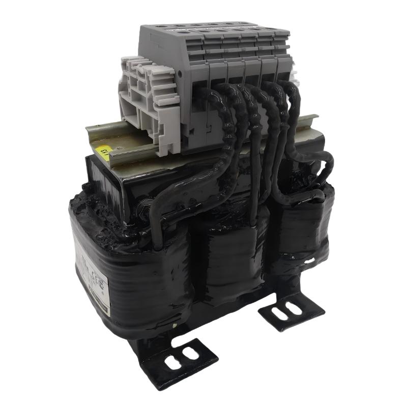
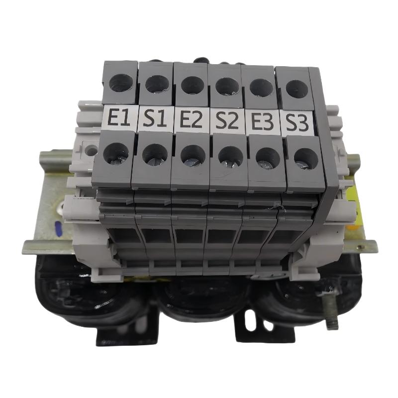
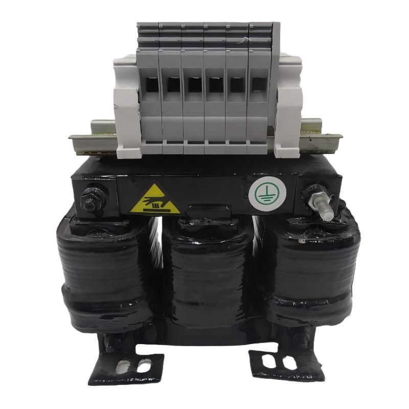
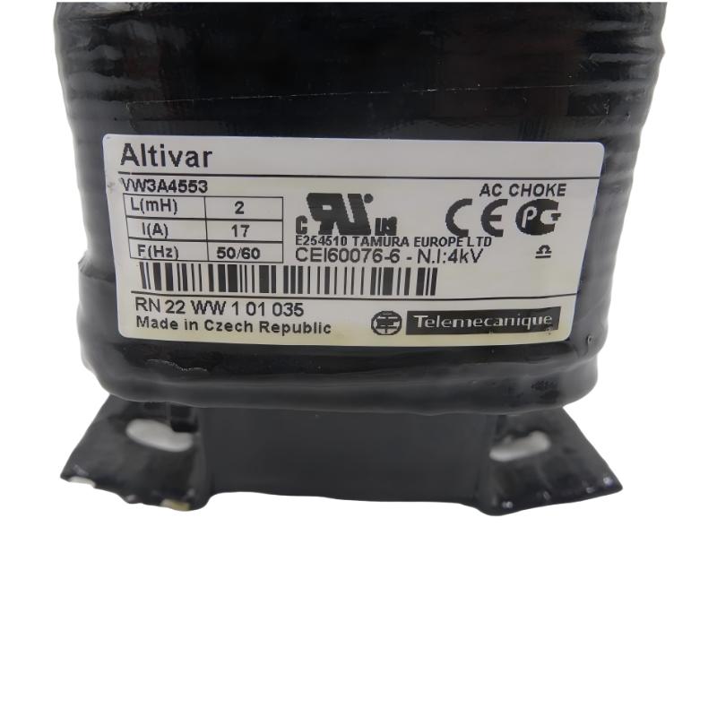
- Schneider
- VW3A4553
- Line/Motor Choke
- France
- 155 × 130 × 90 mm
- 3.5 kg
- Xiamen, China
- New & In Stock
- T/T, PayPal, Western Union
- 1 Year
- 1-3 Working Days
- DHL, UPS, TNT, FedEx and EMS.
- 24-Hour Service
- COO
- 4
Our advantage

Global Logistics
We have a 10-year logistics and express cooperation agreement, so our products can be shipped to any place in the world.

Brand new and original
Our products are imported in bulk from the place of origin. Because of the cooperative relationship, our products are all original and 100% new.

24-hour service
We provide 7*24 hours service to our customers. We will be there whenever you need us.

Price advantage
All our products are priced very favorably because we have our own warehouse and supply.
| Company Information | |||
| [email protected] | |||
| Mobile | +8615980777398 | ||
| +8615980777398 | |||
| 15980777398 |
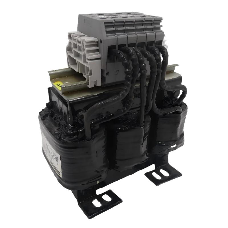
1. Product Overview
The Schneider Electric VW3A4553 Line/Motor Choke is an industrial electrical accessory identified by its model number and supplied product description. Line and motor chokes are used in certain motor-drive installations to influence electrical characteristics within the power circuit. Depending on the specific choke design and application, they may help reduce current disturbances, limit certain electrical transients, or improve the operating conditions of compatible drive systems.
In variable-speed drive installations, electrical accessories must be selected according to the drive model, motor characteristics, supply conditions, cable arrangement, and application requirements. An appropriately specified choke can form part of a drive installation designed to meet the manufacturer’s electrical and operational requirements.
The Schneider Electric VW3A4553 has supplied dimensions of 155 × 130 × 90 mm and a listed weight of 3.5 kg. These specifications help engineers plan installation space, evaluate handling requirements, and manage replacement inventory.
The exact electrical function of the VW3A4553 must be confirmed before installation. The term “Line/Motor Choke” alone does not establish its rated current, inductance, voltage range, supported drive models, or suitability for a particular circuit.
2. Technical Specifications
| Parameter | Specification |
|---|---|
| Brand | Schneider Electric |
| Model | VW3A4553 |
| Product Type | Line/Motor Choke |
| Product Category | Industrial Drive Electrical Accessory |
| Dimensions | 155 × 130 × 90 mm |
| Weight | 3.5 kg |
| Primary Function | Line-side or motor-side inductive filtering, subject to model-specific verification |
| Rated Current | Confirm from the applicable technical documentation |
| Rated Voltage | Confirm from the applicable technical documentation |
| Inductance | Confirm from the applicable technical documentation |
| Compatible Drives | Verify the supported drive models and configurations |
| Installation Location | Confirm whether the unit is intended for line-side or motor-side installation |
| Wiring Requirements | Follow the approved electrical connection diagram |
| Application | Industrial motor-drive systems, subject to compatibility verification |
The dimensions and weight above are the supplied product specifications. Rated current, voltage, inductance, thermal limits, terminal assignments, and supported installation arrangements should be verified from the documentation for the exact model before commissioning.
3. Function and Working Principle
A choke is an inductive electrical component that opposes changes in current. Its effect depends on its inductance, the frequency characteristics of the electrical circuit, and its position within the system.
In motor-drive applications, chokes may be installed on the supply side of a drive or between a drive and a motor. These positions serve different purposes and are not interchangeable without considering the equipment design.
3.1 Line-Side Choke
A line choke is installed on the supply side of a drive when the drive manufacturer specifies or permits its use. Depending on the design, it may help reduce certain current disturbances, limit the rate of current change, or improve the electrical conditions seen by the drive.
The actual benefit depends on the choke’s electrical ratings, the supply network, and the drive configuration. A line choke should not automatically be assumed to provide every form of harmonic mitigation or surge protection.
3.2 Motor-Side Choke
A motor choke is installed between a drive output and the connected motor when specified for the application. Depending on its design, it may help moderate certain output-current or voltage characteristics and support installations with particular motor-cable arrangements.
Its suitability depends on the drive’s output characteristics, the motor, the cable length, and the manufacturer’s recommendations.
3.3 Inductive Behavior
An inductor stores energy in a magnetic field as current flows through it. Its impedance increases with frequency, which influences how current components behave in an electrical circuit.
The practical effect of the VW3A4553 depends on its documented electrical characteristics and whether it is intended for line-side or motor-side use. These details must be verified before determining its operating role.
4. Role in Industrial Motor-Drive Systems
Variable-speed drives regulate motor operation by controlling electrical power delivered to the motor. Additional electrical components may be required to satisfy the installation’s electrical, thermal, and operational requirements.
4.1 Electrical Compatibility
The choke must match the electrical characteristics of the circuit in which it will be installed. Incorrect selection can lead to excessive current, unwanted voltage drop, overheating, or inadequate performance.
4.2 Drive and Motor Integration
A compatible choke can form part of the electrical interface between a drive and its supply or motor. The correct connection point depends on the accessory’s design and the manufacturer’s approved wiring arrangement.
4.3 Power Quality Considerations
Certain line-side inductors can influence current waveforms and electrical disturbances. The extent of any improvement depends on the component specifications and the wider electrical system.
4.4 Motor-Cable Applications
Some motor-side chokes are used in drive installations where motor-cable characteristics require additional consideration. Engineers should evaluate cable length, motor insulation requirements, and drive output characteristics before selecting an accessory.
4.5 Equipment Reliability
Correctly specified electrical accessories can help an installation operate within its intended electrical limits. Reliability still depends on appropriate sizing, correct wiring, adequate ventilation, and compliance with the drive manufacturer’s instructions.
5. Industrial Applications
The VW3A4553 may be considered for industrial motor-drive applications only after its exact electrical ratings and intended installation position have been confirmed.
Manufacturing Machinery
Production equipment often uses variable-speed drives to regulate motor speed and torque. Suitable electrical accessories may be specified to meet the requirements of the drive and the connected motor.
Conveyor Systems
Conveyors rely on controlled motor operation to move products and materials. Where the drive manufacturer specifies a choke, the component must be selected according to the motor, drive, and electrical installation.
Packaging Equipment
Packaging machinery may use drives to control motors in feeding, conveying, and other machine operations. Appropriate drive accessories can support the intended electrical arrangement when correctly specified.
Pumps and Fans
Industrial pumps and fans frequently use variable-speed drives to adjust operating speed. Any line or motor choke used in these systems must meet the electrical and thermal requirements of the selected drive installation.
Material Handling Systems
Lifting, transfer, and material-handling equipment may use motor-drive systems with specific electrical integration requirements. Accessory selection should account for the drive’s operating conditions and the application’s duty cycle.
Industrial Equipment Modernization
When replacing a choke or upgrading a drive system, engineers should verify that the accessory is suitable for the new electrical configuration. A replacement should not be selected solely because its dimensions or product description appear similar.
These examples describe general applications for appropriately rated line or motor chokes. They do not independently confirm the VW3A4553’s suitability for every application listed.
6. Installation and System Integration
Installation of a line or motor choke involves electrical hazards and must be performed by qualified personnel. The following steps provide a general checklist; the model-specific instructions and approved system wiring diagram take precedence.
Step 1: Verify the Model
Confirm that the product label identifies the unit as VW3A4553. Compare the model number with the drive documentation, electrical drawings, and bill of materials.
Step 2: Confirm the Intended Circuit Position
Determine whether the specific unit is approved for line-side installation, motor-side installation, or another defined arrangement. Do not connect it to the supply or drive output based solely on the general product description.
Step 3: Isolate All Relevant Energy Sources
Place the equipment in a safe state and disconnect the relevant power sources according to the site’s lockout/tagout procedure. Follow the drive manufacturer’s discharge and waiting-time requirements, and verify the absence of hazardous voltage using an appropriate instrument before working on the circuit.
Step 4: Check Electrical Ratings
Verify the rated voltage, current, inductance, thermal limits, and other required electrical characteristics. Ensure that the selected choke is suitable for the drive, motor, and installation conditions.
Step 5: Inspect the Component
Check the enclosure, terminals, mounting points, and visible insulation for damage or contamination. Do not install a component that shows signs of physical damage or overheating.
Step 6: Confirm the Mounting Arrangement
Use the supplied dimensions of 155 × 130 × 90 mm for preliminary planning. Verify the required clearances, mounting orientation, ventilation, and access for electrical connections.
Step 7: Connect According to the Approved Diagram
Use the specified terminals, conductor sizes, protective arrangements, and fastening requirements. Do not infer terminal assignments from appearance or assume that line-side and motor-side wiring arrangements are equivalent.
Step 8: Check Grounding and Cable Routing
Follow the manufacturer’s requirements for protective grounding, cable routing, and separation from sensitive signal wiring. Confirm that the completed arrangement complies with applicable electrical installation standards.
Step 9: Inspect Before Energizing
Check all electrical connections, protective covers, mounting fasteners, and wiring clearances. Verify that the choke is installed in the intended circuit position and that no tools or loose materials remain in the equipment.
Step 10: Commission the System
Restore power only after the required safety checks are complete. Monitor the drive and motor during commissioning, and check for abnormal noise, excessive temperature, unexpected current, or diagnostic faults. Follow the approved commissioning procedure for the complete installation.
7. Common Problems and Troubleshooting
Problems associated with a line or motor choke may result from incorrect selection, wiring errors, unsuitable operating conditions, or faults elsewhere in the drive system.
| Symptom | Possible Cause | Recommended Action |
|---|---|---|
| Choke becomes excessively hot | Incorrect rating, excessive current, poor ventilation, or unsuitable operating conditions | Stop operation safely and verify the electrical ratings and installation conditions |
| Drive reports an overcurrent fault | Incorrect wiring, unsuitable component selection, or a fault in the drive or motor circuit | Review the wiring diagram and investigate the drive and motor circuit |
| Motor operation is abnormal | Incorrect installation position, incompatible choke, or another drive-system fault | Verify the accessory’s intended use and check the drive and motor configuration |
| Unexpected voltage drop | Inappropriate inductance or excessive circuit current | Check the choke specifications and application requirements |
| Abnormal buzzing or vibration | Loose mounting, electrical operating conditions, or component damage | Isolate the equipment and inspect the mounting and component condition |
| Drive experiences repeated faults | Incorrect accessory selection or an unrelated system problem | Review diagnostic records and verify the complete electrical configuration |
| Fault remains after replacement | The original cause may be elsewhere in the circuit | Check the drive, motor, cables, supply, and associated protection devices |
7.1 Check the Electrical Ratings
Verify that the installed choke matches the required current, voltage, and application. An unsuitable rating can affect performance and may cause overheating or other electrical problems.
7.2 Verify the Wiring Position
Confirm whether the component belongs on the supply side or motor side of the drive. Incorrect placement can compromise the intended function and may damage equipment.
7.3 Inspect Connections
Loose or incorrectly terminated connections can create localized heating and unreliable operation. Inspection and corrective work must be performed with the equipment safely isolated.
7.4 Review Drive Diagnostics
Record the exact fault codes and operating conditions before changing the configuration. Drive diagnostics may help distinguish a choke-related issue from a motor, cable, supply, or controller fault.
7.5 Evaluate Operating Conditions
Check ventilation, ambient temperature, current loading, and the installation arrangement against the product’s specified limits. Do not continue operation if the component shows signs of overheating or damage.
7.6 Replace Only With a Verified Equivalent
If testing indicates that the choke requires replacement, confirm the electrical specifications and compatibility of the replacement. Similar dimensions or a similar model description do not establish electrical equivalence.
8. Preventive Maintenance and Reliability
Appropriate maintenance helps identify developing electrical or mechanical problems before they cause avoidable equipment downtime.
- Inspect the enclosure and terminals: Look for damage, discoloration, corrosion, and signs of overheating.
- Check mounting security: Verify that the component remains securely mounted according to the approved procedure.
- Monitor operating temperature: Investigate unusual heating in accordance with the manufacturer’s limits.
- Inspect electrical connections: Check for loose or damaged connections during scheduled maintenance, with the equipment safely isolated.
- Maintain ventilation: Keep the installation free from obstructions that could interfere with required cooling.
- Review drive fault history: Investigate recurring overcurrent, temperature, or related diagnostic events.
- Maintain accurate records: Document the model, installation position, relevant electrical specifications, and replacement history.
- Use approved spare parts: Verify electrical equivalence before installing a replacement.
Maintenance intervals should reflect the operating environment, equipment duty cycle, system criticality, and the manufacturer’s recommendations.
9. Compatible System Components
Compatibility for the VW3A4553 should be assessed as part of the complete drive installation. The following table identifies component categories that may require verification; it does not confirm compatibility with specific models.
| Component Category | Verification Requirements |
|---|---|
| Variable-speed drive | Confirm approved accessory combinations and electrical ratings |
| AC motor | Verify motor characteristics and application requirements |
| Power supply | Check the relevant voltage, current, and supply conditions |
| Motor cable | Evaluate cable specifications and length where relevant to the choke’s function |
| Electrical protection | Confirm the required protective devices and installation arrangement |
| Wiring and terminals | Verify conductor sizing, terminal assignments, and connection requirements |
| Mounting structure | Confirm mechanical fit, clearances, and ventilation |
| Control and monitoring equipment | Ensure that the accessory installation does not interfere with the approved control arrangement |
The final selection must be based on the exact drive model, electrical circuit, and manufacturer’s instructions. A choke should not be assumed compatible simply because it is from the same brand.
10. Replacement and Alternative Selection
When replacing the Schneider Electric VW3A4553 Line/Motor Choke, engineers should compare its electrical and mechanical characteristics with the requirements of the original installation.
| Selection Factor | What to Verify |
|---|---|
| Exact model | Confirm VW3A4553 and any relevant revision details |
| Intended function | Establish whether the component is specified for line-side or motor-side use |
| Rated current | Match the required current rating and application conditions |
| Rated voltage | Confirm compatibility with the electrical circuit |
| Inductance | Verify the required inductance and applicable tolerances |
| Drive compatibility | Check the approved drive models and configurations |
| Motor and cable requirements | Evaluate the connected motor and cable arrangement where applicable |
| Dimensions | Compare the supplied dimensions of 155 × 130 × 90 mm with the available installation space |
| Weight | Use the supplied weight of 3.5 kg for handling and mounting planning |
| Product condition | Evaluate whether the component is new, refurbished, or used and inspect its condition |
| Commissioning | Determine the necessary electrical checks and functional validation |
An alternative should be selected only after its electrical characteristics, installation position, and compatibility have been confirmed. A physically similar choke may have a different inductance or current rating and may not be a suitable replacement.
11. Key Benefits of Correct Choke Selection
Selecting an appropriate choke can support a well-designed industrial motor-drive installation.
Electrical Compatibility
A correctly specified component helps match the electrical requirements of the drive circuit and avoids the risks associated with unsuitable ratings.
Support for Drive-System Design
Where required by the manufacturer’s design, a suitable choke can help achieve the intended electrical behavior of the supply or motor circuit.
Better Equipment Integration
Matching the choke to the drive, motor, and wiring arrangement helps maintain consistency with the approved system design.
Practical Installation Planning
The supplied dimensions of 155 × 130 × 90 mm help engineers assess installation space, while the listed weight of 3.5 kg supports preliminary handling and mounting planning.
More Reliable Maintenance
Accurate product identification and documentation make it easier to manage spare parts and investigate electrical faults.
The actual performance benefits depend on the choke’s verified electrical specifications and the requirements of the complete installation.
12. Technical FAQs
Q1: What is the Schneider Electric VW3A4553?
The VW3A4553 is identified in the supplied product information as a Schneider Electric Line/Motor Choke. Its exact electrical function and intended circuit position should be confirmed from the applicable technical documentation.
Q2: What are the dimensions of the VW3A4553?
The supplied dimensions are 155 × 130 × 90 mm.
Q3: How much does the VW3A4553 weigh?
The supplied product weight is 3.5 kg.
Q4: What does a line or motor choke do?
A choke is an inductive component that influences current changes in an electrical circuit. Its specific effect depends on its design and whether it is installed on the supply side or motor side of a drive.
Q5: Can the VW3A4553 be used with any Schneider Electric drive?
No. Compatibility depends on the exact drive model, electrical ratings, intended installation position, and applicable manufacturer requirements.
Q6: How can I determine whether it is a line-side or motor-side component?
Check the model-specific product documentation and approved wiring diagram. Do not determine the installation position from the general product name alone.
Q7: What should be checked before installation?
Verify the model number, rated current, voltage, inductance, intended circuit position, wiring requirements, drive compatibility, mounting arrangement, and ventilation requirements.
Q8: Why might a choke overheat?
Possible causes include excessive current, an unsuitable rating, inadequate ventilation, incorrect installation, or another electrical problem. Safely isolate the equipment and investigate the cause before returning it to service.
Q9: Can a similar choke replace the VW3A4553?
Only if its electrical ratings, inductance, intended function, and compatibility with the drive installation are confirmed. Similar dimensions or appearance are not sufficient.
Q10: What should be done if drive faults continue after replacement?
Review the drive diagnostics and check the supply, motor, cables, electrical connections, protection devices, and configuration. The underlying problem may not be the choke itself.
13. Conclusion
The Schneider Electric VW3A4553 Line/Motor Choke is an industrial drive accessory with supplied dimensions of 155 × 130 × 90 mm and a listed weight of 3.5 kg. It is intended to be evaluated as part of an electrical drive installation, with its precise function determined by the applicable product documentation.
Before installation or replacement, engineers should verify the rated current, voltage, inductance, intended circuit position, and compatibility with the target drive and motor. Correct selection, safe wiring practices, appropriate commissioning, and routine inspection help support dependable operation and reduce avoidable equipment faults.
For maintenance and procurement purposes, always confirm the complete model designation and electrical requirements before selecting the VW3A4553 or an alternative component.