

ProductPRODUCT
Featured products


Contact Us
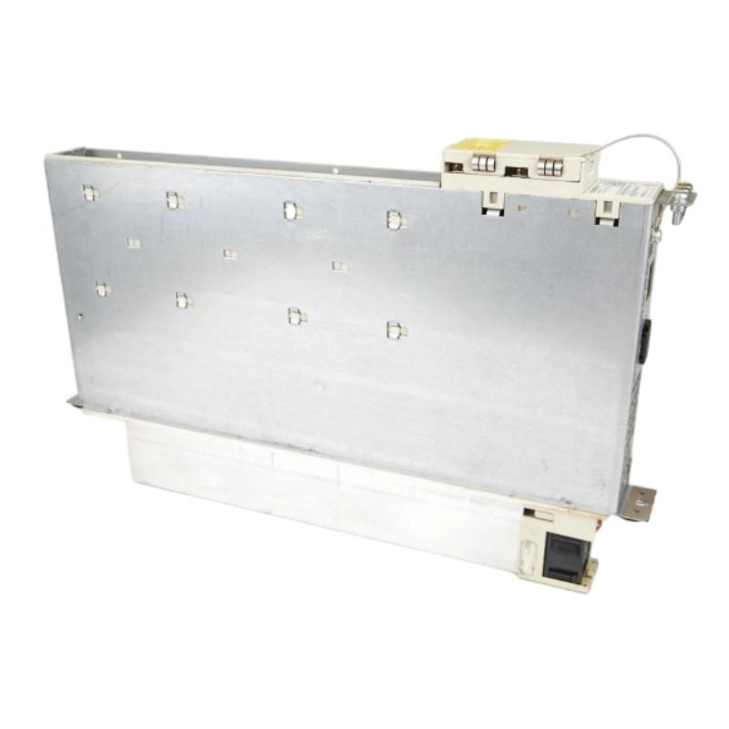
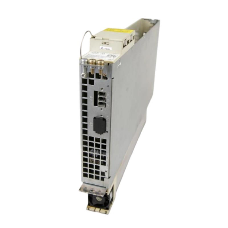
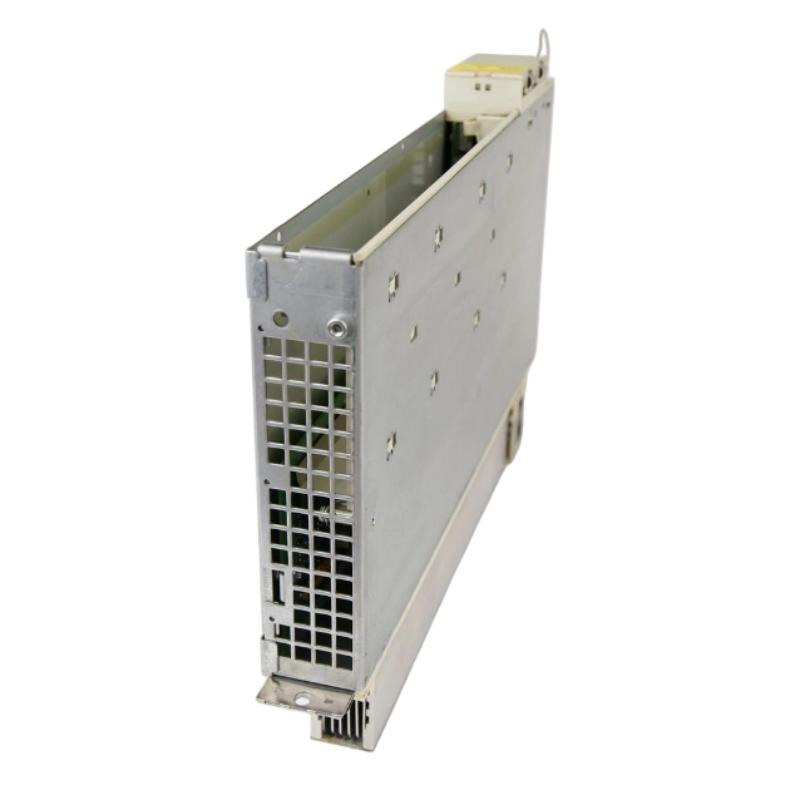
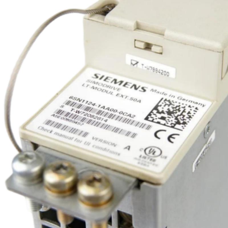
- Siemens
- 6SN1124-1AA00-0CA2
- Power Module
- Germany
- 356 × 76 × 559 mm
- 6 kg
- Xiamen, China
- New & In Stock
- T/T, PayPal, Western Union
- 1 Year
- 1-3 Working Days
- DHL, UPS, TNT, FedEx and EMS.
- 24-Hour Service
- COO
- 4
Our advantage

Global Logistics
We have a 10-year logistics and express cooperation agreement, so our products can be shipped to any place in the world.

Brand new and original
Our products are imported in bulk from the place of origin. Because of the cooperative relationship, our products are all original and 100% new.

24-hour service
We provide 7*24 hours service to our customers. We will be there whenever you need us.

Price advantage
All our products are priced very favorably because we have our own warehouse and supply.
| Company Information | |||
| [email protected] | |||
| Mobile | +8615980777398 | ||
| +8615980777398 | |||
| 15980777398 |
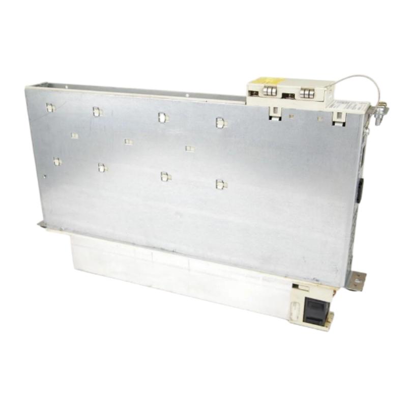
1. Product Overview
The Siemens 6SN1124-1AA00-0CA2 Power Module is an industrial drive component intended for use in compatible Siemens motion-control and drive systems. Power modules play an important role in industrial automation by handling electrical power within a drive assembly and supporting the controlled operation of connected motors.
In manufacturing environments, reliable drive components are essential for machine positioning, coordinated movement, and continuous production. Selecting the correct power module helps maintain system compatibility, simplify maintenance, and reduce the risk of unplanned equipment downtime.
The complete model number, 6SN1124-1AA00-0CA2, should be used when identifying the component, requesting a quotation, or planning a replacement. Modules with similar part numbers may have different electrical ratings, configurations, or operating requirements. Therefore, compatibility should always be verified against the installed drive system and its technical documentation.
The supplied dimensions of 356 × 76 × 559 mm and weight of 6 kg are useful for spare-parts identification, cabinet planning, and transportation arrangements. Before installation, the mounting orientation and mechanical clearances should be confirmed using the appropriate product drawings.
2. Technical Specifications
| Parameter | Specification |
|---|---|
| Brand | Siemens |
| Model Number | 6SN1124-1AA00-0CA2 |
| Product Type | Power Module |
| Product Category | Industrial Drive and Motion Control |
| Dimensions | 356 × 76 × 559 mm |
| Weight | 6 kg |
| Primary Function | Power handling within a compatible drive system |
| Application | Industrial automation and machine-drive systems |
| Installation | Compatible drive assembly or control cabinet |
| Electrical Ratings | Verify against the product nameplate |
| Motor Compatibility | Confirm against the host drive configuration |
| Cooling Requirements | Verify using the applicable technical documentation |
| System Interface | Confirm before installation or replacement |
Note: Dimensions and weight are based on the supplied product information. Electrical ratings, output current, supported motor configurations, and specific drive-system compatibility should be verified before purchase or commissioning.
3. Function and Working Principle
A power module forms part of the electrical power stage of an industrial drive system. Its role is to work with compatible drive-control electronics and associated components to provide the power required for motor operation.
3.1 Electrical Power Handling
Industrial motors require electrical power appropriate to their design and operating conditions. A drive system manages this power to support the required machine movement.
The power module participates in the drive’s power-handling process. Its precise electrical topology and operating limits depend on the specific hardware design, so these details should be confirmed from the module’s documentation rather than inferred from the model number alone.
3.2 Supporting Controlled Motion
In an automated machine, the drive system converts control commands into motor operation. Speed, torque, acceleration, and positioning depend on the combined performance of the controller, drive electronics, power components, motor, and any required feedback devices.
The power module contributes to this overall system but should not be regarded as an independent motion controller.
3.3 Integration with Drive Electronics
Industrial drive architectures commonly separate command processing from power handling. Control electronics interpret commands and manage operating conditions, while the power stage handles the electrical energy needed by the motor.
For the Siemens 6SN1124-1AA00-0CA2, the correct host system, electrical connections, and supporting hardware must be established before installation.
3.4 Operating Reliability
Drive reliability depends on suitable electrical conditions, correct wiring, appropriate cooling, and operation within specified limits. Fault protection and monitoring may involve several components within the complete drive assembly.
When an alarm occurs, technicians should examine the available diagnostic information and the condition of the entire system before deciding that the power module has failed.
4. Role in Industrial Automation Systems
Power modules are important in industrial equipment where electric motors provide controlled mechanical movement. Their role is especially relevant in applications that require repeatable motion, predictable machine response, and coordinated operation.
CNC Machines and Machine Tools
CNC machines use drive systems to control machine axes and execute programmed movement. A compatible power module can form part of the drive assembly responsible for supplying the motor power required by these movements.
Correct hardware selection helps maintain the intended configuration and supports effective machine maintenance.
Automated Manufacturing Lines
Assembly equipment, production machinery, and automated workstations rely on controlled movement to position components and perform repeated operations. Drive-system reliability can directly affect production availability and process consistency.
Material Handling Equipment
Conveyors, positioning mechanisms, and transfer systems may use motor-driven assemblies to move products or materials. The suitability of a particular power module depends on the electrical and mechanical requirements of the complete drive system.
Industrial Machinery Maintenance
When an existing machine experiences a drive fault, replacing a defective component may help restore operation. However, the replacement must match the original equipment requirements. Similar dimensions or a related model number are not sufficient proof of compatibility.
5. Installation and System Integration
Correct installation helps reduce electrical risks and prevents damage to the module or connected equipment. The following procedure is a general guide; the manufacturer’s instructions for the exact module and host drive take precedence.
Step 1: Verify the Model Number
Check the module label and confirm that the required part number is 6SN1124-1AA00-0CA2. Compare it with the machine’s parts list and the original component specification.
Do not assume that a module with a similar number has identical electrical characteristics or is interchangeable.
Step 2: Isolate Electrical Power
Disconnect the equipment from its power source and follow the site’s lockout/tagout procedure. Allow the specified discharge period to elapse, then verify the absence of hazardous voltage using a suitable measuring instrument.
Drive systems can retain dangerous electrical energy after disconnection. Installation and servicing must be performed by qualified personnel.
Step 3: Inspect the Module
Check for shipping damage, contamination, corrosion, loose parts, or other visible defects. Verify that the cabinet provides the required mounting space and that cooling paths will not be obstructed.
Use the supplied dimensions of 356 × 76 × 559 mm for preliminary planning, but confirm the orientation and mounting details from the relevant mechanical drawing.
Step 4: Confirm System Compatibility
Before connecting the module, verify:
- Compatibility with the existing drive system.
- Required input and output electrical ratings.
- Supported motor and axis configuration.
- Power and control connection arrangements.
- Grounding and protective bonding requirements.
- Cooling method and installation clearances.
- Required system configuration and commissioning steps.
If any critical specification is unknown, obtain the correct documentation before proceeding.
Step 5: Install and Connect
Mount the module according to the manufacturer’s installation instructions. Use the specified mounting hardware and follow the approved wiring diagrams.
Check power connections, protective earth, control connections, and other relevant interfaces. Never identify terminals solely by appearance or wire color.
Step 6: Perform Pre-Energization Checks
Inspect the completed installation for loose connections, wiring errors, unsecured components, and blocked ventilation paths. Confirm that the drive assembly complies with the applicable electrical and safety requirements.
Step 7: Commission the System
Restore power according to the equipment’s approved commissioning procedure. Check diagnostic messages and verify that the drive system recognizes and operates with the installed hardware where applicable.
Conduct functional tests under controlled conditions. Confirm stable operation before returning the machine to normal production.
6. Troubleshooting Common Problems
A drive fault does not necessarily indicate a defective power module. Problems may originate from the incoming supply, control electronics, motor, feedback devices, wiring, cooling system, or mechanical load.
6.1 Drive Does Not Start
Possible causes:
- Incoming power is unavailable or outside the permitted range.
- A required enable signal or interlock is missing.
- The drive has not completed its startup sequence.
- Wiring or connections are incorrect.
- Another component has triggered a system fault.
Recommended checks:
Review the drive’s diagnostic messages and verify the supply and enable conditions. Inspect relevant connections after safely isolating the equipment. Follow the manufacturer’s troubleshooting procedure before replacing the module.
6.2 Overcurrent or Overload Alarm
Possible causes:
- Excessive mechanical load.
- Motor or power-circuit wiring problems.
- Incorrect drive configuration.
- A fault in the motor or another drive component.
- A problem in the power stage.
Recommended checks:
Review the alarm history and compare actual operating conditions with the system’s permitted limits. Check the motor and associated wiring using approved procedures. Determine the source of the fault before installing another module.
6.3 Overtemperature Alarm
Possible causes:
- Restricted airflow.
- Excessive cabinet temperature.
- Cooling-system malfunction.
- Operation outside the specified duty conditions.
- Internal hardware failure.
Recommended checks:
Inspect cabinet ventilation and cooling equipment. Remove dust using an approved maintenance method and confirm that required clearances are maintained. Do not continue operating the drive until the cause has been addressed.
6.4 Intermittent Operation
Possible causes:
- Loose connections.
- Unstable electrical supply.
- Electrical interference.
- Intermittent faults in associated control or feedback devices.
- Excessive temperature or vibration.
Recommended checks:
Record when the fault occurs and review the diagnostic history. Inspect the relevant connections and environmental conditions. Internal electrical testing should be performed only by qualified personnel using suitable equipment.
6.5 Fault Persists After Module Replacement
Possible causes:
- The replacement module is not compatible.
- Connections were installed incorrectly.
- Required commissioning steps have not been completed.
- Another component remains defective.
- The original fault has not been corrected.
Recommended checks:
Confirm the full part number and system compatibility. Review the wiring diagrams, diagnostic messages, and commissioning requirements. Avoid repeated component replacement without identifying the underlying cause.
7. Preventive Maintenance
A structured maintenance plan can help improve drive-system reliability and reduce unexpected production interruptions.
- Visual inspection: Check for contamination, corrosion, damage, and signs of overheating.
- Cooling maintenance: Keep ventilation paths clear and inspect cabinet cooling equipment.
- Connection checks: Inspect relevant electrical connections according to the manufacturer’s maintenance procedure.
- Alarm monitoring: Record recurring faults and investigate their root causes.
- Environmental control: Maintain operating conditions within the specified temperature, humidity, and contamination limits.
- Spare-parts management: Record complete model numbers and verify replacement compatibility before ordering.
- Maintenance documentation: Keep records of installation, inspection, fault history, and component replacement.
Always isolate electrical power and verify the absence of hazardous voltage before carrying out maintenance that exposes personnel to electrical hazards.
8. Compatible System Components
The Siemens 6SN1124-1AA00-0CA2 should be evaluated as part of the complete drive system. The following component categories may be relevant to integration, but the table does not establish compatibility with any particular part number.
| Component Category | Function | Verification Requirement |
|---|---|---|
| Drive control unit | Manages drive commands and operating functions | Confirm supported system architecture |
| Electric motor | Converts electrical power into mechanical movement | Verify motor ratings and drive requirements |
| Feedback device | Supplies position or speed information when required | Confirm interface and feedback compatibility |
| Power supply assembly | Provides electrical power to the drive system | Check voltage, capacity, and configuration |
| Cooling equipment | Maintains suitable operating temperatures | Confirm the required cooling method |
| Machine controller | Coordinates machine sequences and motion commands | Verify system configuration |
| Protective devices | Support electrical protection and safe operation | Follow the approved electrical design |
Before ordering components, consult the equipment’s original parts list, electrical drawings, and applicable technical documentation.
9. Replacement and Alternative Selection
Selecting a replacement power module requires more than matching its dimensions or general product category. Electrical specifications and system compatibility are the primary considerations.
Important Selection Factors
- Exact part number: Confirm whether 6SN1124-1AA00-0CA2 is the original required model.
- Electrical ratings: Verify the relevant input, output, current, and power characteristics.
- Host drive compatibility: Confirm that the proposed module supports the installed drive architecture.
- Motor requirements: Check the motor and load specifications.
- Mechanical fit: Verify dimensions, mounting points, orientation, and clearances.
- Cooling requirements: Confirm that the cabinet and drive assembly provide the necessary cooling.
- Commissioning requirements: Determine whether configuration changes or additional checks are required.
| Replacement Approach | Suitable Situation | Key Consideration |
|---|---|---|
| Exact-model replacement | The original module requires replacement | Confirm model number and component condition |
| Manufacturer-approved equivalent | The original part is unavailable | Obtain documented compatibility confirmation |
| Drive-system upgrade | The existing system is obsolete or difficult to maintain | Evaluate the complete drive and control architecture |
| Professional repair | The original module may be repairable | Use qualified service and verify operation before reuse |
A related model should not be treated as a direct substitute unless its suitability has been confirmed for the target system.
10. Key Advantages of Correct Component Selection
Using the appropriate power module in a compatible drive system can provide several practical benefits:
- Configuration consistency: Helps preserve the intended equipment architecture.
- Reliable operation: Supports stable performance when the drive is installed and operated correctly.
- Simplified maintenance: Makes component identification and spare-parts planning more straightforward.
- Reduced replacement risk: Exact model verification helps prevent unsuitable substitutions.
- More effective troubleshooting: Accurate component records support faster fault diagnosis.
- Long-term equipment support: Appropriate maintenance and compatible replacements help preserve existing machinery.
These benefits depend on correct engineering, installation, commissioning, and preventive maintenance.
11. Frequently Asked Questions
What is the Siemens 6SN1124-1AA00-0CA2?
It is identified as a Siemens industrial power module for use in a compatible drive configuration. The exact electrical ratings and supported applications should be confirmed using the product label and technical documentation.
What are the dimensions and weight of this module?
The supplied dimensions are 356 × 76 × 559 mm, and the supplied weight is 6 kg. Verify the measurement orientation and mounting requirements before planning installation.
Is the 6SN1124-1AA00-0CA2 compatible with every Siemens drive?
No. Compatibility depends on the drive architecture, electrical ratings, interfaces, motor requirements, and system configuration. Verify the complete model number against the original equipment documentation.
What should be checked before replacing the module?
Confirm the part number, electrical ratings, wiring, mounting arrangement, cooling requirements, and compatibility with the host drive. Follow the applicable safety and commissioning procedures.
Why might the drive continue reporting faults after replacement?
Possible causes include an incompatible replacement, incorrect wiring, incomplete commissioning, a defective associated component, or an unresolved mechanical or electrical problem. Review the diagnostic information before concluding that the new module is defective.
How can maintenance teams reduce module failures?
Maintain appropriate cooling, inspect connections, monitor recurring alarms, control cabinet conditions, and operate the system within specified limits. Follow the manufacturer’s procedures for all inspection and maintenance work.
How can a suitable alternative be identified?
Start with the original part number and host drive model. Then verify electrical ratings, motor requirements, interface details, mounting conditions, and documented compatibility. Do not rely on visual similarity alone.
12. Conclusion
The Siemens 6SN1124-1AA00-0CA2 Power Module is an industrial drive component whose suitability depends on the requirements of the complete automation system. Correct identification, safe installation, appropriate cooling, and systematic troubleshooting are essential for reliable operation.
For industrial maintenance teams, system integrators, and spare-parts purchasers, the complete model number provides a key reference for sourcing and replacement. Before installation or purchase, verify the electrical specifications and compatibility with the existing drive configuration. Careful selection and preventive maintenance can help reduce avoidable downtime and support dependable industrial machinery operation.