

ProductPRODUCT
Featured products
Contact Us
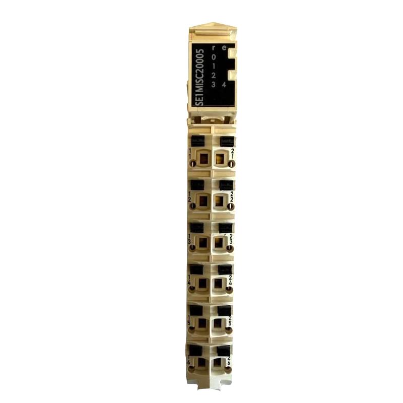
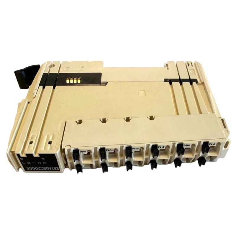
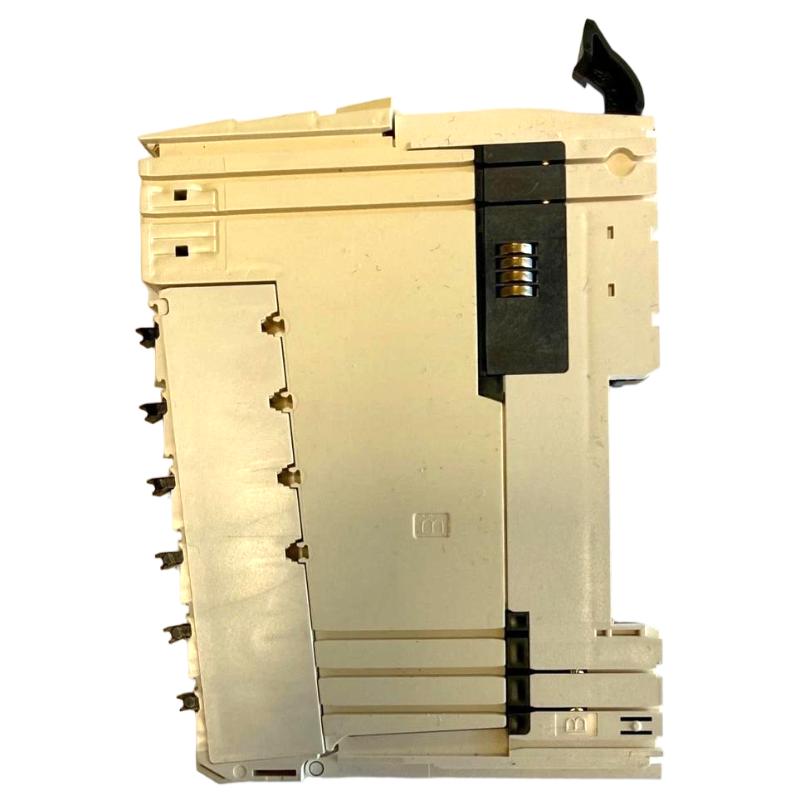

- Schneider
- TM5SE1MISC20005
- Counter Module
- France
- 99 × 12.5 × 75 mm
- 0.025 kg
- Xiamen, China
- New & In Stock
- T/T, PayPal, Western Union
- 1 Year
- 1-3 Working Days
- DHL, UPS, TNT, FedEx and EMS.
- 24-Hour Service
- COO
- 3
Our advantage

Global Logistics
We have a 10-year logistics and express cooperation agreement, so our products can be shipped to any place in the world.

Brand new and original
Our products are imported in bulk from the place of origin. Because of the cooperative relationship, our products are all original and 100% new.

24-hour service
We provide 7*24 hours service to our customers. We will be there whenever you need us.

Price advantage
All our products are priced very favorably because we have our own warehouse and supply.
| Company Information | |||
| [email protected] | |||
| Mobile | +8615980777398 | ||
| +8615980777398 | |||
| 15980777398 |
1. Product Overview
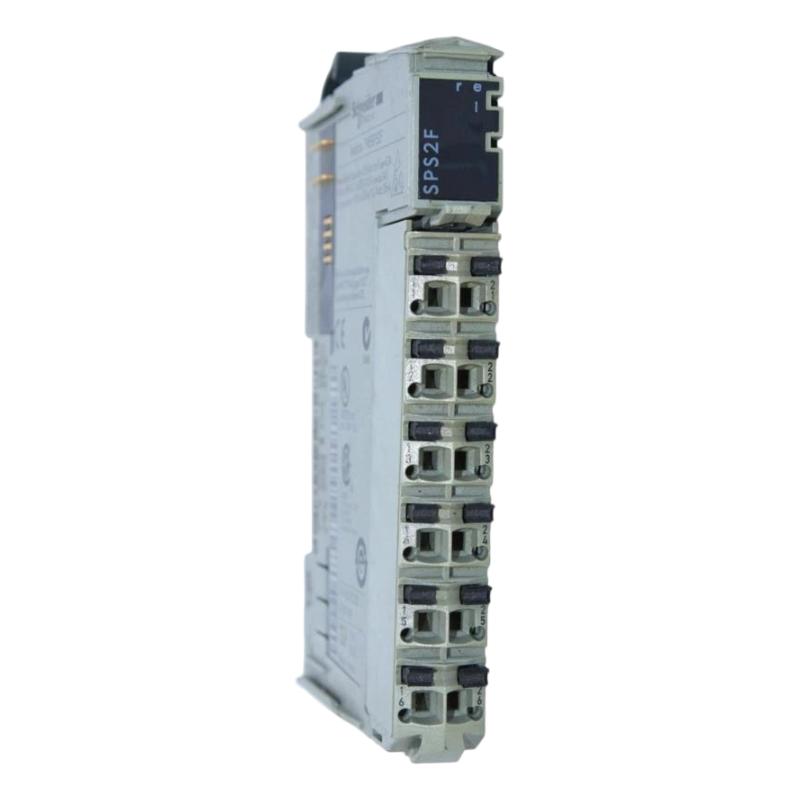
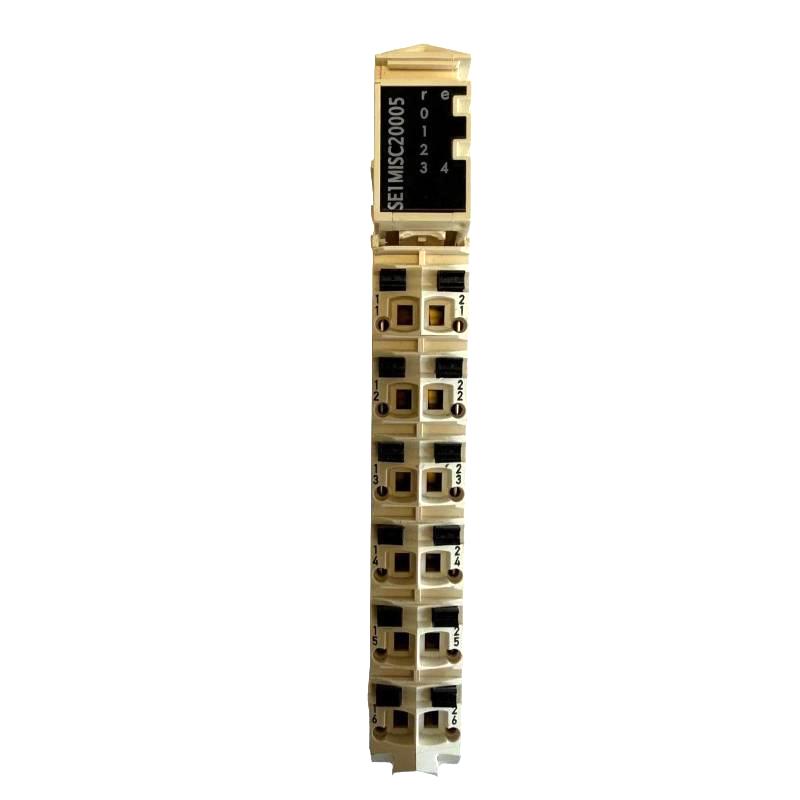
The Schneider Electric TM5SE1MISC20005 Counter Module is an industrial automation component identified for counter-related applications in modular control systems. Counter modules are used in automation environments where pulse signals, repetitive events, or movement-related information must be processed to support machine operation and production monitoring.
In industrial control applications, counting functions can help track product quantities, monitor machine cycles, acquire sensor signals, and support movement-related measurements. The resulting information can be incorporated into a PLC program to evaluate process conditions, update production totals, or trigger control actions when configured appropriately.
The TM5SE1MISC20005 is supplied with dimensions of 99 × 12.5 × 75 mm and a weight of 0.025 kg. Its compact physical size is useful when planning control cabinet layouts, maintaining spare-parts inventories, and identifying replacement components.
For automation engineers, equipment manufacturers, and maintenance teams, correct model identification is essential. Modules with similar product numbers may differ in their input interfaces, counting capabilities, electrical requirements, and controller compatibility. The exact specifications of the TM5SE1MISC20005 should therefore be verified before installation, commissioning, or replacement.
2. Technical Specifications
| Parameter | Specification |
|---|---|
| Brand | Schneider Electric |
| Model | TM5SE1MISC20005 |
| Product Type | Counter Module |
| Product Family | Modicon TM5 |
| Dimensions | 99 × 12.5 × 75 mm |
| Weight | 0.025 kg |
| Primary Application | Counter-related signal acquisition and processing |
| Input Signal Type | Verify against the exact model documentation |
| Counting Frequency | Verify against the exact model documentation |
| Operating Voltage | Verify against the exact model documentation |
| Supported Counter Modes | Confirm from the model-specific technical documentation |
| Controller Compatibility | Verify against the applicable hardware compatibility information |
| Mounting and Connection Accessories | Confirm the required components for this model |
| Typical Applications | Machine automation, production counting, event monitoring, and process measurement |
Note: Dimensions and weight are based on the supplied product information. Electrical ratings, counting performance, signal interfaces, and controller compatibility should be confirmed using documentation for the exact model.
3. Function and Working Principle
Counter modules are designed to acquire supported input signals and process information associated with repeated events or movement. Depending on the hardware design, the resulting data can be used by an automation controller to monitor machine activity and execute programmed control sequences.
Pulse Signal Acquisition
Industrial sensors and encoders may generate pulses when products pass a detection point, a shaft rotates, or a mechanism moves. A compatible counter module processes these signals according to its supported input characteristics.
The controller can then use the count information to evaluate machine status, track activity, or calculate process-related values.
Event and Production Counting
Production equipment frequently needs to record the number of completed cycles, products, or operations. Counter information can be used by the PLC to compare actual production with a preset target.
For example, a packaging line may use a count value to determine when a batch is complete. The accuracy of this process depends on appropriate sensor selection, reliable signal acquisition, and correct application programming.
Movement-Related Monitoring
Where the module supports the connected signal source, counting information may be used to monitor repetitive movement or encoder pulses. Applications can include conveyor monitoring, indexing mechanisms, and machine movement tracking.
The relationship between a count value and actual mechanical movement depends on the sensor or encoder resolution, the mechanical installation, and the controller’s calculations.
Integration with PLC Logic
A counter module generally operates as part of a larger automation architecture. The PLC or motion controller processes available data and coordinates related equipment, including motors, drives, actuators, and operator interfaces.
Before implementing a particular counting function with the TM5SE1MISC20005, verify that the exact model supports the required signal type and operating mode.
4. Role in Industrial Automation Systems
Counter-related signal processing can provide useful information for machines that rely on repetitive events or pulse-based measurements. Within a compatible control system, this information can help operators monitor production and support automated sequencing.
A typical automation system may include:
- PLC or motion controller: Executes the control program and processes the acquired information.
- Counter module: Handles supported input signals and counting functions.
- Sensor or encoder: Generates pulses representing machine events or movement.
- Power supply: Provides the required electrical power to the module and field devices.
- Connection accessories: Provide the necessary mounting and electrical interfaces.
- HMI: Displays production totals, operating status, and alarms when configured.
- Industrial communication equipment: Connects the controller to other devices or supervisory systems where required.
The module’s exact role depends on its confirmed capabilities and the architecture of the installed control system.
5. Industrial Applications
Packaging Machinery
Packaging equipment often requires product counting, batch monitoring, and machine-sequence coordination. Counter data can help a PLC track completed operations and initiate programmed actions when production targets are reached.
Conveyor Systems
Conveyor applications may use sensors to count products or monitor movement-related events. Reliable counting requires correct sensor placement, compatible electrical signals, and suitable signal processing.
Automated Assembly Equipment
Assembly machinery often performs repeated operations in a controlled sequence. Counter information can help determine whether a specified number of operations has been completed before the system advances to another stage.
Material Handling
Material handling equipment can use counting functions to monitor repeated movements, track discrete events, or support production reporting. The signal interface must be appropriate for the sensor used in the application.
General Industrial Monitoring
Counting-related data can support operational monitoring by recording repetitive events or changes in machine activity. The available functions depend on the module’s verified specifications and the controller program.
6. Installation and System Integration
Correct installation helps maintain signal reliability and reduces the risk of configuration errors or unexpected downtime.
Step 1: Confirm the Model Number
Inspect the product label and verify that the module is TM5SE1MISC20005. Make sure the model number matches the intended hardware configuration and procurement records.
Do not rely on a similar model number when choosing wiring diagrams or configuration settings.
Step 2: Verify Controller Compatibility
Confirm that the intended PLC or motion controller supports the exact module. Review the hardware configuration requirements, firmware compatibility, and engineering software support before proceeding.
Step 3: Check Mounting and Connection Components
Identify the required mounting base, terminal block, and other connection accessories using the model-specific documentation. Inspect all components for damage and confirm that the installation arrangement is correct.
Step 4: Isolate Electrical Power
Disconnect the relevant power supplies before installation or wiring. Follow the site’s lockout/tagout procedures and verify that the equipment is in a safe condition before working on electrical connections.
Step 5: Connect the Field Device
Use the correct wiring diagram to identify the input terminals and common connections. Confirm that the sensor or encoder’s output type, voltage, polarity, and supply requirements match the module’s specifications.
Incorrect wiring or an incompatible signal can lead to unreliable operation or equipment damage.
Step 6: Configure the Controller
Add the correct hardware to the controller configuration using the supported engineering software. Configure the required parameters and application logic based on the functions documented for the exact module.
Step 7: Commission the Installation
After checking wiring and configuration, restore power according to the approved procedure. Confirm that the controller recognizes the hardware and check the available diagnostic indicators.
Test the module with known input events and compare the recorded count with the actual process before returning the machine to normal production.
7. Troubleshooting Common Problems
Counter Values Do Not Change
Possible causes:
- The connected sensor or encoder is not generating pulses.
- Field-device power is missing.
- Signal wiring is loose or incorrect.
- The input signal is not supported by the module.
- The controller configuration is incorrect.
Recommended actions:
- Check the sensor or encoder’s power supply and operation.
- Inspect wiring against the model-specific diagram.
- Review the controller’s hardware configuration.
- Verify that the signal meets the module’s electrical requirements.
Counts Are Inconsistent
Possible causes:
- Electrical interference from motors, drives, or switching equipment.
- Poor cable routing or shielding.
- Loose terminals or intermittent connections.
- Sensor misalignment or mechanical vibration.
- An unsuitable signal type or input configuration.
Recommended actions:
- Inspect the field wiring and terminal connections.
- Separate signal cables from high-power wiring where practical.
- Check sensor mounting and mechanical stability.
- Compare the count values with the actual number of events.
Controller Does Not Recognize the Module
Possible causes:
- The wrong module has been selected in the hardware configuration.
- Controller or firmware compatibility requirements are not met.
- The module is not installed correctly.
- A fault exists in the module or associated connection components.
Recommended actions:
- Verify the complete product number.
- Check the controller’s hardware compatibility information.
- Inspect the module and connection components.
- Review controller diagnostics before replacing hardware.
Counting Performance Is Unsatisfactory
Possible causes:
- The input frequency exceeds the module’s supported limit.
- The signal voltage or format is incompatible.
- Wiring introduces electrical noise or signal distortion.
- The application program processes the data incorrectly.
Recommended actions:
- Determine the maximum expected input frequency.
- Confirm the module’s documented counting performance.
- Check the sensor’s output specifications and wiring.
- Test the application using known input conditions.
8. Compatible System Components
| Component Category | Function | Verification Required |
|---|---|---|
| PLC or motion controller | Executes the control application | Confirm explicit support for TM5SE1MISC20005 |
| Mounting base | Provides the required mechanical interface | Verify the correct component for the module |
| Terminal block | Provides electrical connections | Confirm the compatible part number |
| Pulse sensor | Detects repetitive events | Match output type and electrical characteristics |
| Encoder | Supplies movement-related signals | Confirm supported interface and signal format |
| DC power supply | Supplies module or field-device power | Verify voltage and current requirements |
| HMI | Displays count values and machine status | Configure through the control application |
| Industrial network equipment | Connects the controller with other devices | Verify the network architecture and controller interfaces |
Compatibility should be confirmed for the exact module and controller combination. Do not assume that accessories used with another TM5 module are automatically suitable for this model.
9. Replacement and Alternative Selection
When sourcing a replacement for the TM5SE1MISC20005, physical dimensions alone are not enough to establish compatibility. The replacement must meet the original application’s electrical, functional, and system-integration requirements.
| Selection Criterion | What to Check |
|---|---|
| Product identification | Exact model number and hardware revision |
| Input signal compatibility | Supported signal type, voltage, and wiring arrangement |
| Counting performance | Maximum input frequency and response requirements |
| Counter functions | Required counting or measurement modes |
| Controller compatibility | PLC model, firmware, and engineering software |
| Mounting arrangement | Required base and installation dimensions |
| Electrical connections | Terminal assignments and accessory requirements |
| Application performance | Correct operation under actual machine conditions |
If an exact replacement is unavailable, verify functional equivalence with the applicable technical documentation or a qualified automation engineer. Similar product numbers do not guarantee that two modules are interchangeable.
10. Key Advantages
- Compact design: The supplied dimensions of 99 × 12.5 × 75 mm support space-conscious installation planning.
- Low specified weight: The supplied weight of 0.025 kg is useful for handling and inventory records.
- Counter-related functionality: Intended for evaluation in applications requiring counting-related signal processing, subject to verification of exact capabilities.
- PLC application integration: Counting information can be incorporated into supported control logic.
- Flexible system design: Counter-based solutions can support production monitoring and machine sequencing.
- Simplified maintenance identification: Accurate model information helps reduce spare-parts selection errors.
11. Technical FAQs
Q1: What is the Schneider TM5SE1MISC20005 Counter Module used for?
It is identified as a counter module for industrial automation. Its specific signal interface and counting functions should be confirmed using documentation for the exact model.
Q2: What are its dimensions and weight?
The supplied dimensions are 99 × 12.5 × 75 mm, and the supplied weight is 0.025 kg.
Q3: Can it be connected to an encoder?
Encoder compatibility depends on the module’s supported signal interface, electrical ratings, and wiring requirements. Verify these characteristics before making a connection.
Q4: Which PLC controllers are compatible?
Check the manufacturer’s compatibility documentation for the exact TM5SE1MISC20005 model and the intended controller. Compatibility should not be inferred from another module in the product family.
Q5: Why might the counter fail to register pulses?
Potential causes include missing field-device power, incorrect wiring, an unsupported input signal, incorrect controller configuration, or a hardware fault. Check these conditions systematically before replacing the module.
Q6: What should be checked before ordering a replacement?
Confirm the complete model number, signal requirements, counting functions, operating voltage, controller compatibility, connection accessories, dimensions, and weight.
Q7: What is the maximum counting frequency?
The maximum counting frequency has not been confirmed here for the exact TM5SE1MISC20005 model. Verify the model-specific technical specifications and compare them with the application’s maximum expected input frequency.
12. Conclusion
The Schneider Electric TM5SE1MISC20005 Counter Module is identified as a counter-related component for industrial automation applications. Its supplied dimensions of 99 × 12.5 × 75 mm and weight of 0.025 kg provide useful information for product identification, installation planning, and spare-parts management.
For reliable integration, engineers should verify the exact model’s input characteristics, counting performance, electrical requirements, controller compatibility, and connection accessories. Correct installation, configuration, and commissioning are essential for dependable operation and effective industrial process monitoring.