

ProductPRODUCT
Featured products
Contact Us
- ABB
- EK175-40-11 SK825440-AM
- AC Contactor
- Sweden (SE)
- 230 × 178 × 207 mm
- 7.05 kg
- Xiamen, China
- New & In Stock
- T/T, PayPal, Western Union
- 1 Year
- 1-3 Working Days
- DHL, UPS, TNT, FedEx and EMS.
- 24-Hour Service
- COO
- 7
Our advantage

Global Logistics
We have a 10-year logistics and express cooperation agreement, so our products can be shipped to any place in the world.

Brand new and original
Our products are imported in bulk from the place of origin. Because of the cooperative relationship, our products are all original and 100% new.

24-hour service
We provide 7*24 hours service to our customers. We will be there whenever you need us.

Price advantage
All our products are priced very favorably because we have our own warehouse and supply.
| Company Information | |||
| [email protected] | |||
| Mobile | +8615980777398 | ||
| +8615980777398 | |||
| 15980777398 |
Product Overview
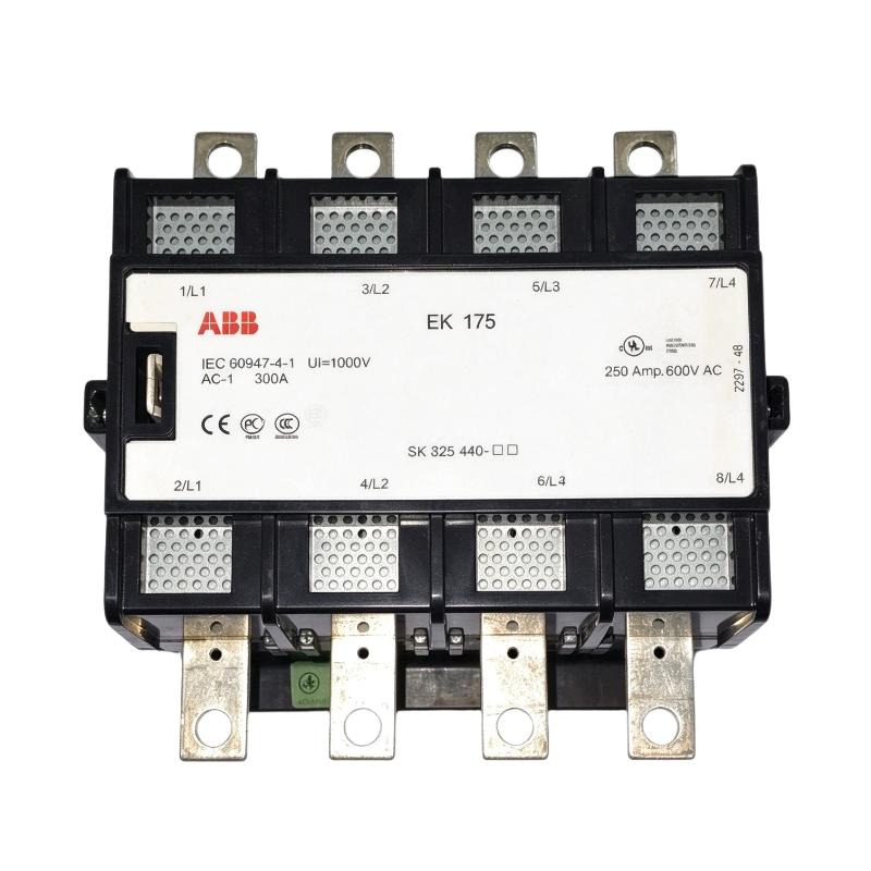
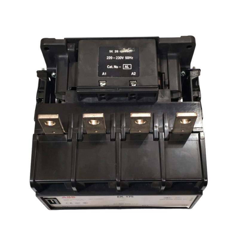
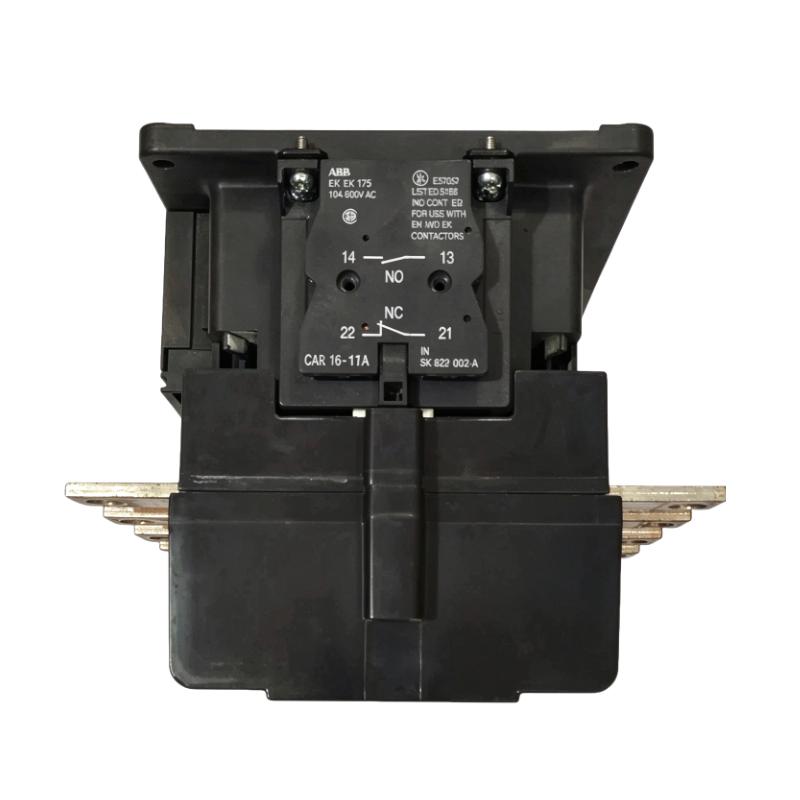
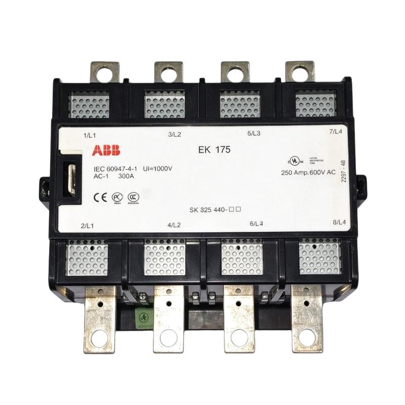
The ABB EK175-40-11 SK825440-AM is a four-pole AC contactor used for switching high-current electrical circuits in industrial installations. It has four normally open main contacts, one normally open auxiliary contact, and one normally closed auxiliary contact. The SK825440-AM designation identifies the version with a 230–240 V AC operating coil at 50 Hz.
This contactor is relevant to motor control panels, industrial power distribution assemblies, and machinery that requires electrically controlled switching. In a motor starter, for example, the EK175-40-11 can connect a compatible motor to the three-phase supply when the control circuit receives a start command. When the coil is de-energized, the main contacts open and disconnect the load, subject to the circuit’s operating conditions.
The contactor has a conventional free-air thermal current rating of 300 A at 40°C and an AC-1 operational current rating of 300 A at 690 V under the specified conditions. For squirrel-cage motor applications, its AC-3 rating is the more relevant selection parameter. The motor’s rated current, starting frequency, switching duty, and operating environment must all be considered before choosing the contactor.
The auxiliary contacts can be used in a contactor holding circuit, an electrical interlock, or a control-system status circuit. This is useful when the contactor operates as part of a larger sequence involving motor overload protection, circuit breakers, PLC commands, and operator push buttons.
For replacement applications, check the complete model and order code rather than selecting by frame size alone. Coil voltage, frequency, main-contact arrangement, auxiliary contacts, and terminal configuration all affect compatibility with the existing installation.
Technical Specifications
| Parameter | Specification |
|---|---|
| Manufacturer | ABB |
| Model | EK175-40-11 |
| Order Code | SK825440-AM |
| Product Family | ABB EK Series |
| Product Type | AC Contactor |
| Main Contact Configuration | 4 NO |
| Auxiliary Contact Configuration | 1 NO + 1 NC |
| Rated Coil Voltage | 230–240 V AC |
| Coil Frequency | 50 Hz |
| Rated Operational Voltage | Up to 1000 V |
| Conventional Free-Air Thermal Current | 300 A at 40°C |
| Rated Operational Current, AC-1 | 300 A at 690 V, 40°C |
| Rated Operational Current, AC-1 at 55°C | 270 A at 690 V |
| Rated Operational Current, AC-1 at 70°C | 215 A at 690 V |
| Rated Operational Current, AC-3 | 210 A at 230/400 V, 55°C |
| Operating Principle | Electromagnetic actuation |
| Number of Main Contacts | 4 normally open |
| Maximum Permissible Operating Altitude | 3000 m |
| Dimensions | 230 × 178 × 207 mm |
| Weight | 7.05 kg |
Product Features
- Four normally open main contacts for switching a compatible four-pole power circuit.
- 230–240 V AC, 50 Hz operating coil for the specified SK825440-AM version.
- One normally open and one normally closed auxiliary contact for control and interlocking functions.
- 300 A AC-1 operational current rating under the specified operating conditions.
- 210 A AC-3 operational current rating at 230/400 V and 55°C.
- Suitable for integration into industrial motor starters and power-switching panels.
- Can operate with appropriately selected circuit breakers, overload relays, and external control devices.
- Requires application-specific protection coordination and correct load selection.
Working Principle
In a typical motor control panel, the EK175-40-11 receives its operating command through a control circuit. When the specified AC voltage energizes the coil, the electromagnetic mechanism moves the contact assembly and closes the four main contacts. Power can then flow from the incoming supply to the connected load.
When the coil supply is removed, the contact mechanism returns to its normal state and opens the main contacts. This allows the contactor to respond to stop commands, control interlocks, or an overload relay’s trip contact when these devices are correctly connected in the control circuit.
The auxiliary contacts provide additional switching states for the control system. The normally open auxiliary contact can maintain a contactor command through a holding circuit, while the normally closed contact can be used for an interlock or complementary status signal.
Typical motor starter arrangement:
Three-Phase Supply → Circuit Breaker → EK175-40-11 → Motor
Control Supply → Stop Circuit and Interlocks → Start Command → Contactor Coil
The contactor switches the load; it does not independently provide complete motor overload and short-circuit protection. Those functions must be handled by appropriately selected protective devices within the complete installation.
Role in an Industrial Motor Control Architecture
The EK175-40-11 occupies the power-switching position between the electrical supply and the connected equipment. The control circuit determines when the contactor operates, while the main contacts carry the load current. Auxiliary contacts can support status feedback and interlocking with other switching devices.
In an automated installation, a PLC may issue the start command through a suitable output interface. Stop commands and required protective interlocks are incorporated into the control arrangement according to the machine’s electrical design.
| System Element | Function |
|---|---|
| EK175-40-11 Contactor | Switches the main power circuit through four normally open contacts |
| SK825440-AM Coil | Operates with the specified 230–240 V AC, 50 Hz control supply |
| Circuit Breaker | Provides the required short-circuit protection and circuit isolation arrangement |
| Motor Overload Relay | Detects motor overload conditions and initiates the configured trip response |
| Control Supply | Supplies the contactor coil at the required voltage |
| PLC or Relay Logic | Coordinates start commands, stop commands, and operating sequences |
| Auxiliary Contacts | Support holding circuits, interlocks, and status signaling |
| Operator Push Buttons | Provide local start and stop commands |
| Three-Phase Motor | Converts electrical power into mechanical output |
| Terminal Blocks | Organize the power and control wiring within the cabinet |
Industrial Applications
| Application | Typical Use |
|---|---|
| Industrial Motor Starters | Switching compatible motors within a coordinated starter assembly |
| Pumping Systems | Controlling motor power for industrial water, process, and utility pumps |
| Ventilation Equipment | Switching compatible fan motors in industrial air-handling installations |
| Compressor Systems | Switching compressor motor circuits when the starting duty matches the contactor rating |
| Power Distribution Panels | Controlling compatible electrical circuits requiring four-pole switching |
| Manufacturing Machinery | Switching motors used in production and processing equipment |
| Plant Utility Systems | Controlling suitable auxiliary motors and other electrical loads |
| Automated Machine Cabinets | Integrating power switching with PLC commands, relay logic, and electrical interlocks |
For motor applications, the contactor must be selected using the applicable AC-3 rating rather than relying solely on its AC-1 rating. Starting frequency, motor current, supply voltage, and operating temperature affect the selection.
Installation and Maintenance
- Confirm the complete EK175-40-11 SK825440-AM designation before installation or replacement.
- Verify that the control supply matches the specified 230–240 V AC, 50 Hz coil.
- Check the load voltage, operating current, and utilization category against the contactor’s applicable ratings.
- For squirrel-cage motor applications, assess the AC-3 rating alongside the motor’s rated current and starting duty.
- Select suitable short-circuit protective devices according to the installation’s prospective fault current and coordination requirements.
- Confirm that the motor overload relay is correctly rated and connected to the contactor control circuit where required.
- Inspect the main power terminals for loose connections, damaged insulation, discoloration, or signs of overheating.
- Verify the normally open and normally closed auxiliary-contact wiring against the actual control schematic.
- Check the mounting arrangement, mechanical support, terminal access, and available maintenance clearance.
- During commissioning, test the coil operation and confirm that the main contacts and associated control circuits respond correctly.
- Investigate coil chatter, unexpected dropouts, excessive heating, or signs of contact wear before returning the equipment to service.
- Record the contactor model, coil specification, wiring arrangement, and associated protection settings for future maintenance and replacement work.
Always isolate the electrical supply and verify the absence of hazardous voltage before carrying out installation or maintenance. Follow the applicable site procedures and electrical safety requirements.
Related Components
| Component | Function |
|---|---|
| Motor Circuit Breaker | Provides the required short-circuit protection and circuit switching |
| Motor Overload Relay | Detects sustained motor overload conditions |
| Control Relay | Interfaces control commands and additional switching signals |
| Control Transformer or AC Supply | Supplies the specified coil voltage where required |
| Auxiliary Contact Block | Adds auxiliary contacts when a compatible accessory is supported |
| Coil Surge Suppressor | Limits switching transients when an appropriate device is selected for the AC coil |
| PLC Output Interface | Connects automation commands to the contactor control circuit |
| Start/Stop Push Buttons | Provides local operator commands |
| Terminal Blocks | Organizes power and control wiring within the panel |
| Three-Phase Motor | Provides the mechanical load in a motor starter application |
Recommended Related Models
| Model / Product | Product Type | Typical Application |
|---|---|---|
| ABB EK150-40-11 SK824441-AM | Four-Pole AC Contactor | Lower-current applications within the same EK contactor family |
| ABB EK175-40-11 SK825440-AM | Four-Pole AC Contactor | Reference model with a 230–240 V AC, 50 Hz coil |
| ABB EK210-40-11 SK825441-AM | Four-Pole AC Contactor | Applications requiring a higher current rating within the EK family |
| ABB AF190-40-11-13100-250VAC/DC (1SFL487102R1311) | Four-Pole AF Contactor | Replacement candidate for installations using the discontinued EK175-40-11 |
The EK150-40-11 and EK210-40-11 are related models with different current ratings. The AF190-40-11-13100-250VAC/DC is a listed replacement reference for the EK175-40-11, but it has a different coil specification and must not be assumed to be a direct drop-in replacement. Confirm the control voltage, contact arrangement, electrical ratings, terminal layout, and mounting requirements before substitution.
Key Advantages
- Four-pole main-contact arrangement.
- Specified 230–240 V AC, 50 Hz operating coil.
- 300 A AC-1 rating under the stated conditions.
- 210 A AC-3 rating at 230/400 V and 55°C.
- NO and NC auxiliary contacts for control logic.
- Suitable for integration into industrial power-switching and motor-control assemblies.
Technical FAQs
What does the SK825440-AM order code identify?
SK825440-AM identifies the EK175-40-11 version with a 230–240 V AC, 50 Hz operating coil. Matching this code helps avoid selecting a replacement with an incompatible coil supply.
Is the 300 A AC-1 rating suitable for a 300 A motor?
Not necessarily. AC-1 applies to non-inductive or slightly inductive loads under specified conditions. For a motor, the AC-3 rating, motor nameplate current, starting conditions, and switching frequency must be assessed. The AC-1 rating alone does not establish suitability for motor duty.
What are the functions of the auxiliary contacts?
The contactor has one normally open and one normally closed auxiliary contact. Depending on the circuit, they can support a holding circuit, electrical interlocking, or status signaling. Their use should follow the actual control schematic.
Can the AF190-40-11-13100-250VAC/DC replace the EK175-40-11 directly?
It is identified as a replacement candidate, but direct substitution should not be assumed. The AF190 version uses a wide-range 100–250 V AC/DC coil, unlike the specified 230–240 V AC, 50 Hz coil of the EK175 version. Check the coil interface, main and auxiliary contacts, electrical ratings, terminal layout, and mounting arrangement before replacing the existing unit.