

ProductPRODUCT
Featured products
Contact Us
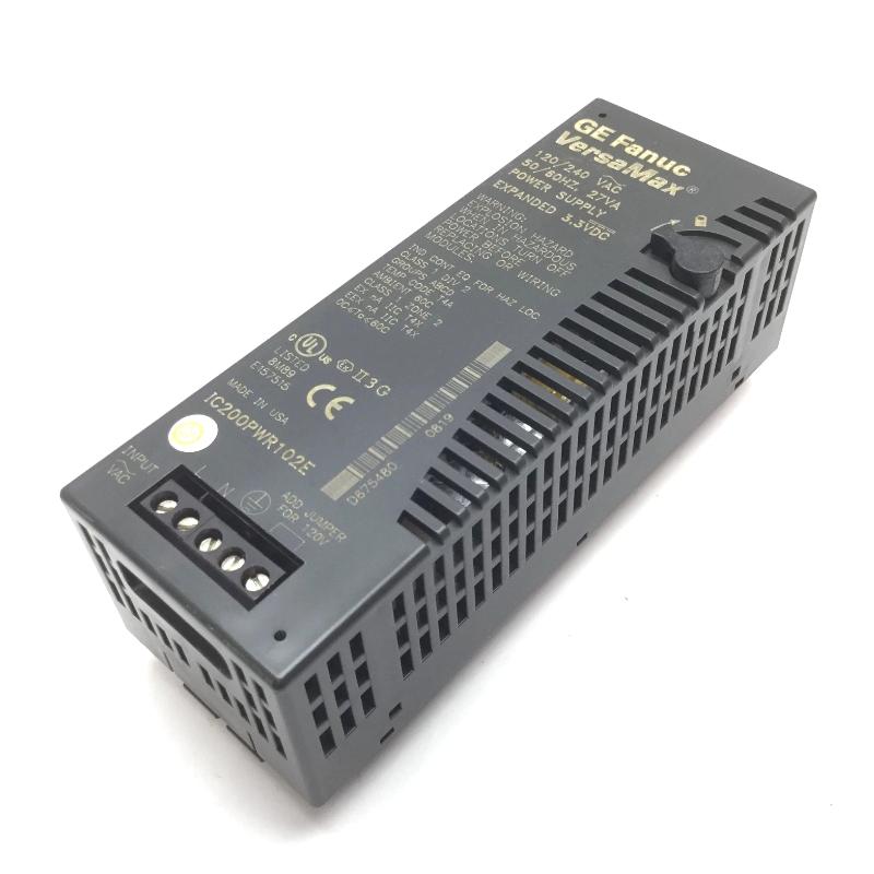
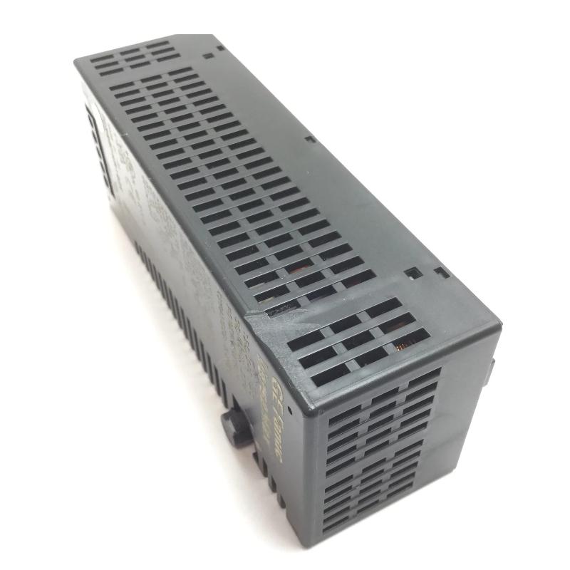
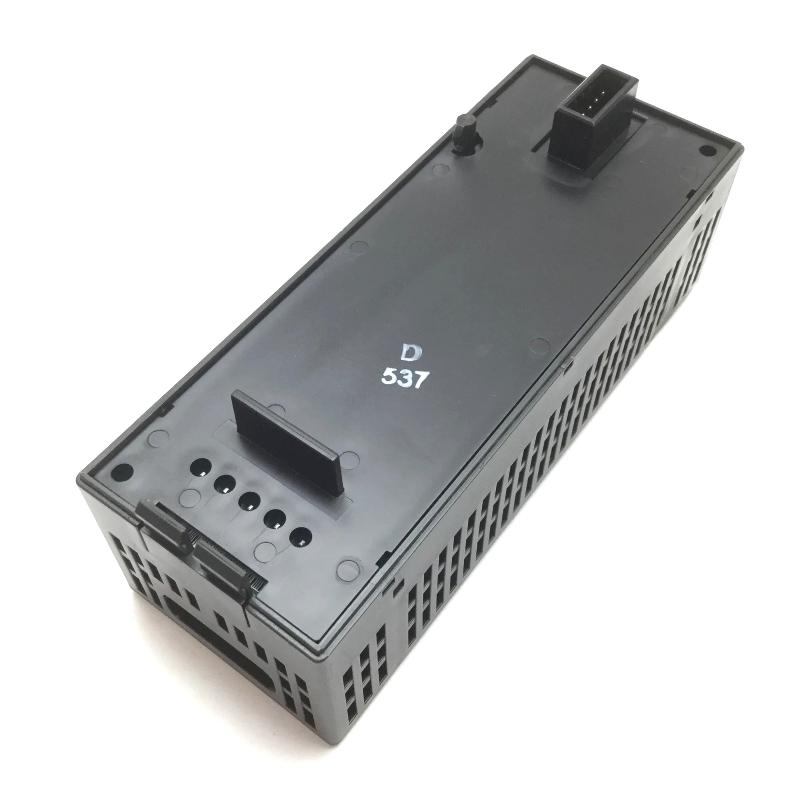
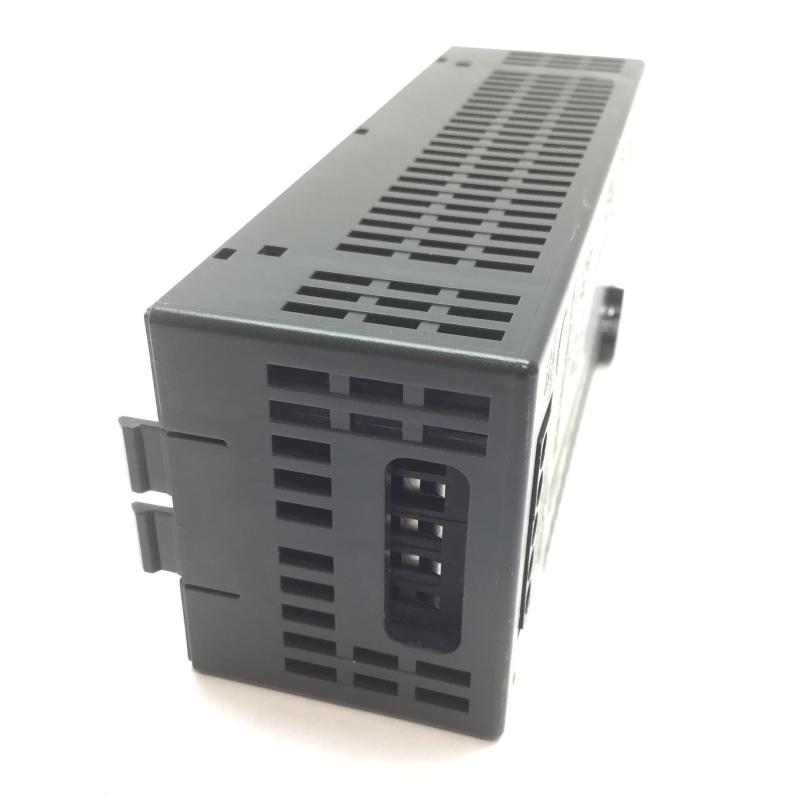
- GE
- IC200PWR102E
- Power Supply Module
- USA
- 133.4 × 39 × 49 mm
- 0.118 kg
- Xiamen, China
- New & In Stock
- T/T, PayPal, Western Union
- 1 Year
- 1-3 Working Days
- DHL, UPS, TNT, FedEx and EMS.
- 24-Hour Service
- COO
- 4
Our advantage

Global Logistics
We have a 10-year logistics and express cooperation agreement, so our products can be shipped to any place in the world.

Brand new and original
Our products are imported in bulk from the place of origin. Because of the cooperative relationship, our products are all original and 100% new.

24-hour service
We provide 7*24 hours service to our customers. We will be there whenever you need us.

Price advantage
All our products are priced very favorably because we have our own warehouse and supply.
| Company Information | |||
| [email protected] | |||
| Mobile | +8615980777398 | ||
| +8615980777398 | |||
| 15980777398 |
Product Overview
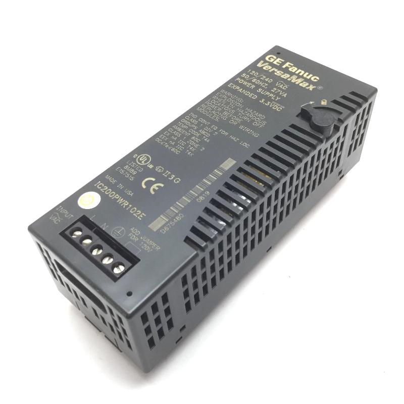
The GE IC200PWR102E is a power supply module used in the VersaMax automation platform. It supports the power requirements of a VersaMax PLC installation, helping the controller and associated I/O hardware operate as part of a coordinated control system. In an industrial control cabinet, the power supply is one of the first components to check when investigating startup failures, intermittent module operation, or unexpected loss of control-system communication.
In a typical VersaMax application, the power supply works alongside the CPU or network interface, I/O modules, and field wiring. Its role is distinct from that of the controller: the CPU executes the control program, while the power supply supports the electrical requirements of the configured hardware. Selecting a suitable supply therefore requires attention to the actual rack arrangement, connected modules, and the power specifications of the complete installation.
The IC200PWR102E is relevant to maintenance and replacement work involving existing VersaMax equipment. Before installing a replacement, engineers should confirm the required supply type, input source, output ratings, and compatibility with the specific VersaMax hardware configuration. Matching the model number alone is not sufficient if the system has been modified or expanded.
Technical Specifications
| Parameter | Specification |
|---|---|
| Brand | GE |
| Model | IC200PWR102E |
| Product Series | VersaMax |
| Product Type | Power Supply Module |
| Automation Platform | GE VersaMax |
| Module Function | Power supply for compatible automation hardware |
| System Role | Supports electrical power requirements of the configured system |
| Installation Environment | Industrial control cabinet |
| System Integration | VersaMax PLC and I/O architecture |
| Primary Application | Industrial automation and control |
| Operating Role | Supports normal operation of compatible system components |
| Maintenance Use | Inspection, servicing, and replacement of installed hardware |
| Configuration Requirement | Must match the system’s documented power requirements |
| Dimensions | 133.4 × 39 × 49 mm |
| Weight | 0.118 kg |
Product Features
- VersaMax platform integration: Belongs to the GE VersaMax automation family and is intended for use within compatible system configurations.
- Power-system support: Supplies the electrical power required by the hardware it is specified to serve, subject to its documented ratings and installation requirements.
- Centralized cabinet installation: Keeps the power supply within the automation hardware arrangement, making it easier to inspect alongside the controller and I/O modules.
- Support for continuous control operation: A correctly specified and functioning power supply helps maintain the operating conditions required by the configured control system.
- Maintenance and replacement use: Can be evaluated for servicing existing VersaMax installations when the original supply requires inspection or replacement.
- System-level compatibility checks: Encourages verification of input requirements, output capacity, and connected hardware before commissioning.
- Integration with modular automation: Fits into a broader control arrangement in which power, processing, communication, and I/O functions are handled by their respective components.
- Practical fault isolation: Provides a defined point for checking supply-related issues when a controller or group of modules fails to start or operates intermittently.
Working Principle
The IC200PWR102E supports the electrical requirements of the compatible VersaMax hardware configuration. Its operation can be understood through the power-up and monitoring sequence of an industrial control system.
- Input power connection: The supply receives electrical power from the source specified for the installed model. Input wiring and protective devices must follow the applicable hardware requirements.
- Power conversion and delivery: The module performs its specified power-supply function and makes the required power available to the compatible system hardware.
- Hardware startup: Once the required power conditions are established, the controller, communication hardware, and I/O components can start according to their own operating sequences.
- Control-system operation: The CPU executes the application logic, communication components exchange data, and I/O modules handle signals. The power supply supports these functions but does not execute the control program itself.
- System response to changing conditions: The supply must remain within its specified operating limits as the connected hardware starts and operates. The actual load must be considered when assessing whether the supply is suitable for the installation.
- Fault investigation: If the system fails to start or experiences repeated resets, technicians should check the incoming source, wiring, protective devices, supply status, connected load, and other possible causes before deciding that the module has failed.
A power supply problem can affect more than one component at a time. For this reason, troubleshooting should distinguish between a supply fault, an input-power issue, excessive system loading, a wiring problem, and a fault in the controller or connected modules.
Role in a VersaMax Control Architecture
The IC200PWR102E occupies the power-support layer of a VersaMax control installation. It works alongside the controller, communication hardware, and I/O modules, each of which performs a separate function within the automation system.
| System Component | Function | Relationship to IC200PWR102E |
|---|---|---|
| VersaMax CPU | Executes application logic and manages control operations | Depends on the specified power arrangement for normal operation |
| VersaMax I/O Modules | Process discrete or analog field signals | Require power appropriate to their hardware and configuration |
| VersaMax Network Interface | Connects the automation system to a communication network | Operates as part of the powered control architecture |
| IC200PWR102E Power Supply Module | Performs its specified power-supply function | Supports compatible system hardware within its rated capacity |
| I/O Carrier or Base | Provides mounting and electrical connections for compatible modules | Establishes the physical arrangement of the installed hardware |
| Field Power Supply | Supplies external field circuits where required | May be separate from the power serving the PLC hardware |
| Circuit Protection | Protects the supply input and associated circuits as specified | Helps manage electrical faults within the installation |
| Control Cabinet Grounding | Provides the required protective grounding arrangement | Supports safe installation and electrical integrity |
Industrial Applications
| Application | Example of Use | Power-Supply Role |
|---|---|---|
| Factory Automation | PLC control cabinets operating automated production equipment | Supports the configured VersaMax hardware |
| Material Handling | Conveyor and transfer systems using modular PLC control | Helps maintain the electrical operating conditions of the control system |
| Packaging Machinery | Automated packaging lines with discrete and analog I/O | Supports controller and I/O hardware as specified |
| Process Monitoring | Control panels collecting process signals and executing logic | Provides power support for compatible automation components |
| Machine Control Panels | Local PLC installations coordinating motors, valves, and sensors through suitable interfaces | Supports the PLC hardware responsible for control decisions |
| Equipment Maintenance | Repair of existing VersaMax-based machinery | Provides a model-specific replacement option after compatibility checks |
| Industrial Retrofits | Upgrades to established control cabinets | Requires verification against the revised hardware and power-load arrangement |
| Production-Line Support | Modular control systems used for machine sequencing and status monitoring | Helps maintain normal operation of compatible control hardware |
The suitability of the IC200PWR102E for a particular application depends on the documented electrical specifications, the system configuration, and the combined requirements of the connected hardware.
Installation and Maintenance
- Verify the module identification: Confirm the complete IC200PWR102E model number and hardware revision before installation or replacement.
- Check the input requirements: Verify the required input source, voltage range, frequency where applicable, and wiring arrangement from the module documentation.
- Isolate power before servicing: Follow the site’s lockout and isolation procedures before disconnecting the supply or accessing its terminals.
- Confirm system compatibility: Check that the module is appropriate for the installed VersaMax hardware and the intended mounting arrangement.
- Assess the connected load: Review the power requirements of the controller, communication hardware, and associated modules to ensure the configured system remains within the supply’s ratings.
- Inspect input wiring: Check terminal tightness, conductor condition, insulation, and wiring polarity or phase requirements as applicable.
- Check protective devices: Verify that upstream circuit protection is appropriate for the supply and installed electrical system.
- Inspect grounding and cabinet conditions: Confirm that grounding, ventilation, and environmental conditions comply with the equipment requirements.
- Examine connectors and mounting: Look for damaged connections, loose mounting hardware, contamination, or signs of overheating.
- Restore power under an approved procedure: After installation checks are complete, energize the system and verify that the supply and connected hardware start normally.
- Investigate abnormal operation: If modules reset, fail to initialize, or behave intermittently, check the incoming source, supply status, load, connections, and other possible system faults.
- Record maintenance results: Document the installed model, hardware revision, inspection findings, measured electrical conditions, and replacement details for future servicing.
Related Components
| Component | Function | Relationship to IC200PWR102E |
|---|---|---|
| GE VersaMax CPU | Executes the control program | Forms the processing part of the powered automation system |
| GE VersaMax I/O Module | Handles field input or output signals | Requires the appropriate power arrangement for the installed configuration |
| GE VersaMax Network Interface | Connects the controller system to an industrial network | Supports communication within the automation architecture |
| GE VersaMax I/O Carrier | Provides module mounting and electrical connections | Helps establish the hardware configuration |
| GE VersaMax Terminal Assembly | Organizes connections between I/O hardware and field wiring | Supports orderly installation and maintenance |
| Input Circuit Protection | Protects the power input circuit | Helps protect the supply and associated wiring |
| Control Cabinet Grounding Components | Provide the required protective grounding path | Support safe cabinet installation |
| External Field Power Supply | Powers field devices where separate field power is required | Complements the PLC hardware supply when the system design calls for separate power sources |
Recommended Related Models
| Model | Product Name | Relationship |
|---|---|---|
| GE IC200PWR001 | VersaMax Power Supply Module | Related VersaMax supply model for comparison of electrical requirements |
| GE IC200PWR002 | VersaMax Power Supply Module | Related power supply model within the VersaMax family |
| GE IC200PWR101 | VersaMax Power Supply Module | Related model for checking supply specifications and system compatibility |
| GE IC200PWR202 | VersaMax Power Supply Module | Alternative VersaMax power supply model requiring configuration-specific verification |
| GE IC200CPU001 | VersaMax CPU Module | Controller component associated with VersaMax automation systems |
| GE IC200CPU002 | VersaMax CPU Module | Related controller model for VersaMax system configuration comparisons |
Key Advantages
- VersaMax system compatibility: Belongs to the GE VersaMax product family.
- Dedicated power-supply function: Supports the electrical requirements of compatible control hardware.
- Simplified maintenance planning: Provides a specific model reference for inspection and replacement work.
- System-level troubleshooting: Helps technicians isolate supply-related issues from controller, I/O, and field-wiring faults.
- Modular automation support: Fits into a control architecture with separate power, processing, communication, and I/O functions.
- Configuration-based selection: Encourages verification of power capacity and hardware requirements before commissioning.
Technical FAQs
1. What is the GE IC200PWR102E used for?
The IC200PWR102E is a GE VersaMax power supply module. It supports the power requirements of compatible automation hardware within the specified system configuration.
2. Is the IC200PWR102E compatible with every VersaMax CPU and I/O configuration?
Compatibility should not be assumed across every VersaMax installation. The supply’s electrical ratings, mounting arrangement, hardware revision, and the requirements of the connected components must be checked against the system documentation.
3. What can cause a VersaMax system to fail to start when using this power supply?
Possible causes include an incorrect or unstable input source, loose wiring, an open protective device, excessive connected load, a defective supply, or a fault elsewhere in the control system. Troubleshooting should begin with the input circuit and proceed through the supply and connected hardware.
4. What should be checked before replacing the IC200PWR102E?
Confirm the complete model number, required input source, output specifications, mounting arrangement, system configuration, and combined power demand of the connected hardware. The replacement should meet the documented requirements of the installed VersaMax system.