

ProductPRODUCT
Featured products
Contact Us
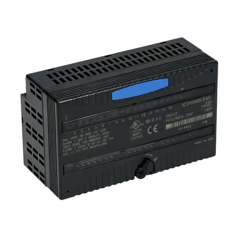
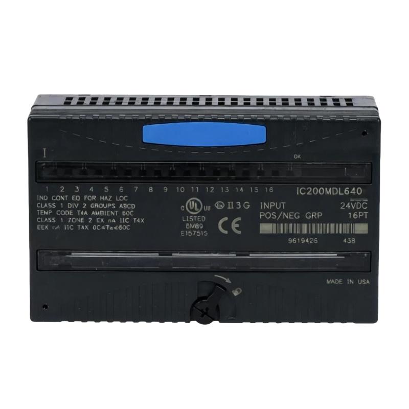
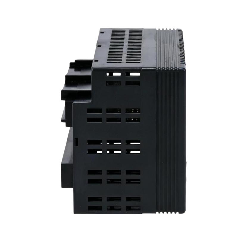
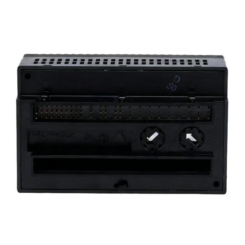
- GE
- IC200MDL640C
- Discrete Input Module
- USA
- 110 × 66.8 × 50 mm
- 0.45 kg
- Xiamen, China
- New & In Stock
- T/T, PayPal, Western Union
- 1 Year
- 1-3 Working Days
- DHL, UPS, TNT, FedEx and EMS.
- 24-Hour Service
- COO
- 4
Our advantage

Global Logistics
We have a 10-year logistics and express cooperation agreement, so our products can be shipped to any place in the world.

Brand new and original
Our products are imported in bulk from the place of origin. Because of the cooperative relationship, our products are all original and 100% new.

24-hour service
We provide 7*24 hours service to our customers. We will be there whenever you need us.

Price advantage
All our products are priced very favorably because we have our own warehouse and supply.
| Company Information | |||
| [email protected] | |||
| Mobile | +8615980777398 | ||
| +8615980777398 | |||
| 15980777398 |
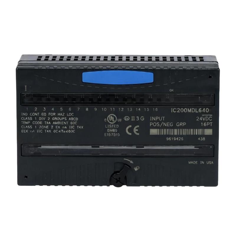
Product Overview
The GE IC200MDL640C VersaMax Discrete Input Module is an industrial automation component used to monitor discrete field signals and transfer their status to a programmable control system. It serves as an interface between field devices, such as push buttons, limit switches, proximity sensors, and auxiliary contacts, and the controller responsible for executing machine logic.
Within a VersaMax automation system, discrete input signals provide information about equipment status, operator commands, interlocks, and process events. The controller uses these signals to determine whether a machine can continue operating, whether a sequence should advance, or whether an alarm condition requires attention. The IC200MDL640C supports this input acquisition function as part of the system’s modular I/O arrangement.
This module is relevant to machine control panels, production equipment, and process automation installations where multiple discrete signals must be monitored by a central controller. During replacement or system maintenance, engineers should verify the module’s electrical input characteristics, terminal arrangement, compatibility with the installed VersaMax carrier or base, and controller configuration before returning the system to service.
Technical Specifications
| Parameter | Specification |
|---|---|
| Brand | GE |
| Model | IC200MDL640C |
| Product Series | VersaMax |
| Product Type | Discrete Input Module |
| Module Category | Digital Input |
| Primary Function | Discrete field signal acquisition |
| Signal Type | On/off digital signals |
| System Platform | VersaMax PLC and I/O system |
| Field Interface | Discrete input connections |
| Input Sources | Switches, sensors, and auxiliary contacts |
| Data Processing | Input status supplied to the controller |
| Mounting Arrangement | Compatible VersaMax I/O base or carrier |
| Application | Industrial machine and process control |
| Hardware Compatibility | Verify against the installed VersaMax configuration |
| Dimensions | 110 × 66.8 × 50 mm |
| Weight | 0.45 kg |
Product Features
- Discrete signal acquisition: Receives on/off status signals from compatible field devices and makes the input information available to the control system.
- VersaMax platform integration: Belongs to the GE VersaMax automation family, supporting modular I/O arrangements used in industrial control panels and machine automation systems.
- Field device monitoring: Can be used to monitor equipment states, limit-switch positions, operator commands, and other discrete conditions when the connected devices meet the module’s input requirements.
- Support for sequence control: Input states can be used by the PLC program to determine when a machine operation may begin, continue, pause, or move to its next programmed step.
- Interlock signal handling: Supplies discrete status information used by the controller to evaluate permissive conditions and operational interlocks.
- Centralized I/O organization: Consolidates multiple discrete signal connections within the control system’s modular I/O structure, helping organize field wiring and controller-side signal handling.
- Controller-based decision making: The module acquires input states, while the PLC program interprets those states and determines the appropriate control response.
- Maintenance and replacement suitability: Can be considered during troubleshooting when a compatible VersaMax system experiences missing, incorrect, or intermittent discrete input signals.
- Integration with other I/O functions: Works as part of a larger control architecture that may include digital outputs, analog inputs, analog outputs, communication interfaces, and controller hardware.
- Configuration-dependent operation: Correct performance depends on the module’s documented electrical characteristics, compatible mounting hardware, field wiring, and controller configuration.
Working Principle
The GE IC200MDL640C acquires discrete electrical signals from field devices and presents their states to the controller through the VersaMax I/O system. A discrete signal generally represents one of two logical conditions, such as a switch being open or closed or a sensor detecting or not detecting an object. The electrical interpretation depends on the input circuit and the connected device.
The typical operating sequence follows these stages:
- Field signal generation: A connected switch, sensor, or auxiliary contact changes its electrical state in response to an operator action or equipment condition.
- Input signal reception: The module receives the field signal through the appropriate input connection.
- Electrical input processing: The input circuitry interprets the incoming signal according to the module’s supported electrical characteristics.
- Input status update: The corresponding input state becomes available to the VersaMax controller through the I/O interface.
- PLC program evaluation: The controller evaluates the input state against its programmed conditions, interlocks, timers, and sequence logic.
- Control response: The program may update internal logic, generate an alarm, or command a compatible output module to operate connected equipment.
For example, a limit switch may indicate that a machine actuator has reached its required position. The discrete input module transfers that status to the controller, and the PLC program determines whether the next machine operation is permitted.
The input module does not independently make machine-level control decisions. Its role is to acquire electrical input states; the controller program determines how those states affect the overall process.
Role in a VersaMax PLC Control Architecture
The IC200MDL640C occupies the field-input layer of a VersaMax control system. It provides the connection between discrete field devices and the controller, allowing the PLC program to use real-world equipment states in its control logic.
| System Component | Function | Relationship to the IC200MDL640C |
|---|---|---|
| VersaMax PLC CPU | Executes the control program | Reads input states and determines the control response |
| IC200MDL640C Input Module | Acquires discrete field signals | Transfers input status to the controller |
| Push Buttons and Selector Switches | Provide operator commands | Supply manual control signals to the input module |
| Proximity Sensors | Detect object presence or position | Provide discrete detection signals where electrically compatible |
| Limit Switches | Indicate mechanical position or travel limits | Supply position and interlock status |
| Auxiliary Contacts | Indicate the state of contactors or other equipment | Provide equipment status feedback |
| VersaMax I/O Base or Carrier | Supports the module’s physical and electrical connection | Provides the required mounting and system interface |
| Digital Output Module | Operates relays, contactors, valves, or other loads | Executes commands generated by the PLC program |
| PLC Programming Software | Configures and monitors the control application | Defines how input states are interpreted and used |
A problem with one input may affect a specific machine sequence, while a loss of communication or a broader I/O fault can affect several control functions. Troubleshooting should distinguish between a field device fault, wiring problem, module failure, mounting-interface issue, and controller configuration error.
Industrial Applications
| Application | Typical Input Monitoring Requirement | Role of the IC200MDL640C |
|---|---|---|
| Automated Assembly Lines | Monitoring part presence, station status, and cycle completion | Supplies discrete status signals for PLC sequence logic |
| Conveyor Systems | Detecting product arrival, accumulation, and position | Transfers sensor states to the controller |
| Packaging Machinery | Monitoring guards, limit switches, and operator commands | Provides input information for machine sequencing and interlocks |
| Material Handling Equipment | Monitoring end positions and equipment status | Supports discrete feedback acquisition |
| Pump and Motor Control Panels | Reading auxiliary contacts and operating status signals | Supplies status information for control and alarm logic |
| Industrial Process Skids | Monitoring valve limit switches and equipment permissives | Provides discrete inputs for the programmed process sequence |
| Machine Safety Status Monitoring | Acquiring designated status signals used by the control program | Supports monitoring functions when used within an appropriately engineered architecture; it is not automatically a safety-rated input module |
| Legacy PLC Installations | Maintaining existing VersaMax-based control systems | Serves as a discrete input component in compatible installations |
The exact application depends on the module’s electrical input specifications and the system design. Safety functions requiring certified safety inputs must use appropriately rated safety hardware and validated safety logic rather than relying on a standard discrete input module alone.
Installation and Maintenance
- Verify the module identification: Confirm the complete IC200MDL640C model number and hardware revision before installation or replacement.
- Check system compatibility: Verify that the module is supported by the installed VersaMax controller, I/O base or carrier, and system configuration.
- Confirm input requirements: Check the documented input voltage, signal thresholds, polarity requirements, and channel arrangement before connecting field devices.
- Isolate the equipment: Follow the site’s electrical safety procedures and isolate the relevant power sources before removing or installing the module.
- Inspect the module and interface: Check the module housing, terminals, contacts, mounting points, and associated base or carrier for damage or contamination.
- Verify field wiring: Confirm terminal assignments, wire identification, connection tightness, and the electrical compatibility of each connected device.
- Check the field devices: Test switches, sensors, and auxiliary contacts to confirm that they change state as expected when the associated equipment operates.
- Install the module correctly: Fit the module to the designated compatible base or carrier and secure it according to the installation procedure. Do not force an incorrectly aligned module into place.
- Review the PLC configuration: Confirm that the module is recognized by the controller and that the configured I/O references correspond to the intended field signals.
- Check input status indications: Where status indicators are provided, compare their behavior with the actual field signal states and the controller’s online input display.
- Test the control sequence: Operate the relevant field devices under approved test conditions and verify that the PLC receives the expected input changes and executes the correct programmed response.
- Document maintenance results: Record the module identification, affected input points, wiring checks, test results, and corrective actions for future maintenance.
If an input remains inactive, check the field device, incoming signal, terminal connection, and electrical compatibility before replacing the module. If several input points fail together, also inspect the module seating, base or carrier, system power, and controller-side I/O status.
Related Components
| Component | Function | Relationship to the IC200MDL640C |
|---|---|---|
| GE VersaMax PLC CPU | Executes the control program | Processes the input states acquired by the module |
| VersaMax I/O Base or Carrier | Provides the module mounting and system interface | Supports the module’s physical and electrical connection |
| VersaMax Digital Output Module | Controls external discrete loads | Executes output commands generated by the PLC program |
| VersaMax Analog Input Module | Acquires analog process measurements | Complements discrete input monitoring |
| VersaMax Analog Output Module | Supplies analog control signals | Supports control functions requiring variable output signals |
| Proximity Sensor | Detects object presence or position | Supplies discrete input signals |
| Limit Switch | Indicates mechanical position | Provides travel-limit and sequence feedback |
| Auxiliary Contact | Indicates the state of electrical equipment | Supplies status feedback to the input module |
| Field Wiring and Terminal Assemblies | Connect field devices to the I/O system | Carry electrical signals into the module |
Recommended Related Models
| Model or Product Family | Product Type | Relevance |
|---|---|---|
| GE IC200MDL640C | VersaMax Discrete Input Module | Target model for compatible discrete input applications |
| GE VersaMax Digital Input Modules | Digital Input Modules | Related products for acquiring discrete field signals; verify individual specifications |
| GE VersaMax Digital Output Modules | Digital Output Modules | Complementary modules for discrete control outputs |
| GE VersaMax Analog Input Modules | Analog Input Modules | Complementary hardware for acquiring variable process signals |
| GE VersaMax Analog Output Modules | Analog Output Modules | Complementary hardware for analog control applications |
| GE VersaMax PLC CPUs | Programmable Logic Controllers | Controller hardware for processing input data and executing automation logic |
Key Advantages
- Acquires discrete field signals for PLC-based monitoring and control.
- Integrates into compatible GE VersaMax modular I/O systems.
- Supports machine sequencing, equipment status monitoring, and interlock logic.
- Works alongside digital and analog I/O modules within a larger automation architecture.
- Provides a module-level maintenance option for compatible VersaMax installations.
Technical FAQs
1. What is the GE IC200MDL640C used for?
The GE IC200MDL640C is a VersaMax discrete input module used to acquire on/off signals from compatible field devices. The PLC uses these signals for machine sequencing, status monitoring, interlocks, and other programmed control functions.
2. Which devices can be connected to the IC200MDL640C?
Potential signal sources include push buttons, selector switches, limit switches, proximity sensors, and equipment auxiliary contacts. Each device must meet the module’s documented electrical input requirements and wiring specifications.
3. Why does an input point remain inactive?
Possible causes include a faulty field device, incorrect wiring, an incompatible input signal, a loose connection, an incorrectly configured I/O reference, or a defective module. Checking the actual field signal and comparing it with the controller’s input status helps isolate the cause.
4. Is the IC200MDL640C a safety-rated input module?
It should not be assumed to be safety-rated simply because it monitors machine status. Safety-related applications require hardware and control architecture with the appropriate safety certification and validated implementation.