

ProductPRODUCT
Featured products
Contact Us
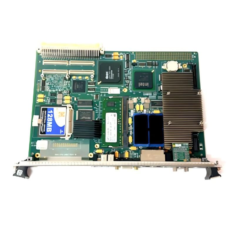
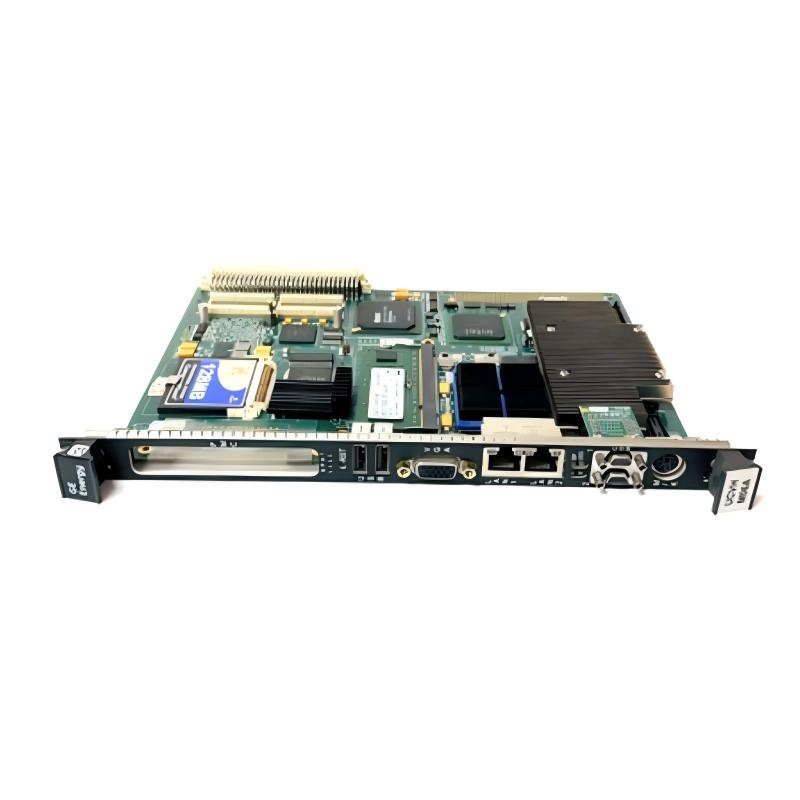
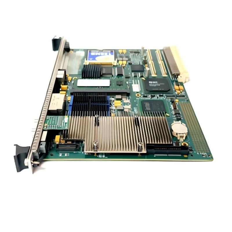
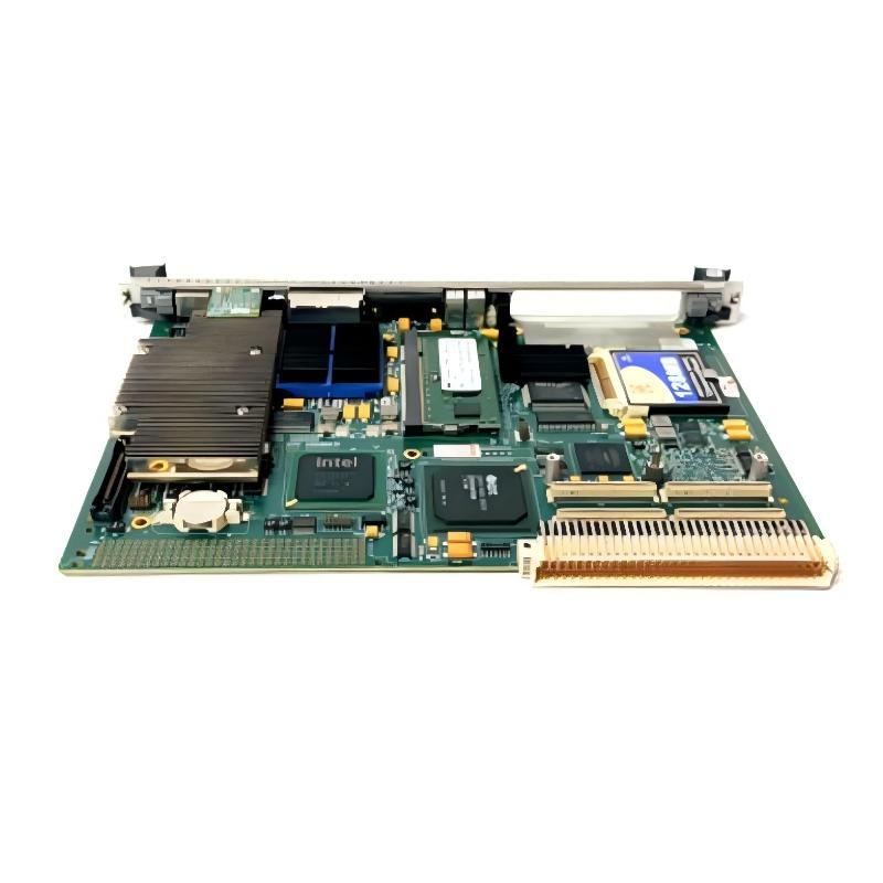
- GE
- IS415UCVHH1AB
- Circuit Board
- USA
- 86.36 x 161.8 mm
- 0.907 kg
- Xiamen, China
- New & In Stock
- T/T, PayPal, Western Union
- 1 Year
- 1-3 Working Days
- DHL, UPS, TNT, FedEx and EMS.
- 24-Hour Service
- COO
- 7
Our advantage

Global Logistics
We have a 10-year logistics and express cooperation agreement, so our products can be shipped to any place in the world.

Brand new and original
Our products are imported in bulk from the place of origin. Because of the cooperative relationship, our products are all original and 100% new.

24-hour service
We provide 7*24 hours service to our customers. We will be there whenever you need us.

Price advantage
All our products are priced very favorably because we have our own warehouse and supply.
| Company Information | |||
| [email protected] | |||
| Mobile | +8615980777398 | ||
| +8615980777398 | |||
| 15980777398 |
Product Overview
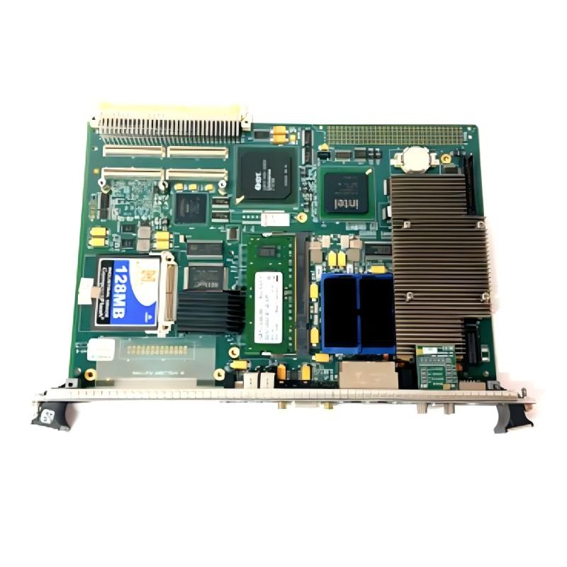
The GE IS415UCVHH1AB Circuit Board is an industrial electronic assembly intended for integration into compatible control equipment. Designed for use in industrial automation environments, this board forms part of the electronic hardware that supports the operation of complex control systems. Circuit boards of this type provide the physical platform for electronic components, signal paths, and electrical connections required by their designated functions within an industrial installation.
In industrial automation, electronic circuit boards help connect control hardware, process interfaces, and supporting electronic assemblies. Depending on the specific design and host system, a board may contribute to signal handling, internal communication, control processing, or coordination between different hardware components. The exact role of the IS415UCVHH1AB should be confirmed against the equipment configuration and applicable technical documentation before installation or replacement.
The GE IS415UCVHH1AB has a listed size of 86.36 × 161.8 mm and a weight of approximately 0.907 kg. Its relatively compact dimensions make it suitable for equipment installations where circuit boards must fit within an established enclosure or mounting arrangement. Accurate identification of the board is essential because industrial circuit boards that appear similar may have different electrical characteristics, connector layouts, firmware requirements, and system functions.
For maintenance engineers, system integrators, and industrial spare-parts specialists, the IS415UCVHH1AB is a component that should be selected according to its complete part number and confirmed application. Proper identification, careful handling, and compatibility checks help reduce replacement errors and support reliable operation of the equipment in which it is installed.
Technical Specifications
| Parameter | Specification |
|---|---|
| Manufacturer | General Electric (GE) |
| Model | IS415UCVHH1AB |
| Product Type | Industrial Circuit Board |
| Product Family | GE IS415 Series |
| Primary Role | Electronic assembly for compatible industrial control equipment |
| Dimensions | 86.36 × 161.8 mm |
| Weight | 0.907 kg |
| Installation | Within compatible equipment or designated mounting assembly |
| Application | Industrial automation and control-system maintenance |
| Compatibility | Must be verified against the host system and hardware revision |
| Replacement Identification | Complete part number and applicable revision |
Note: Detailed electrical ratings, connector assignments, board-level functions, and host-system compatibility should be verified using the technical documentation for the specific installation. The table includes only the product identification and physical information provided for this item.
What Is the GE IS415UCVHH1AB Circuit Board?
The GE IS415UCVHH1AB is identified as an industrial circuit board used in compatible GE control equipment. An industrial circuit board is an electronic assembly that carries components and conductive pathways designed to perform a defined role within a larger electrical or automation system.
Unlike a complete standalone controller, a circuit board may operate as one part of a broader hardware architecture. Its function depends on the components installed on the board, the signals or power supplied through its connections, and the way it interacts with other assemblies in the host equipment.
Industrial control systems commonly contain several interconnected hardware layers. These can include processing electronics, input and output interfaces, communication assemblies, terminal boards, power-distribution components, and operator-interface equipment. A dedicated circuit board may support one of these layers, but its precise purpose cannot be established from physical dimensions or a model number alone.
For the IS415UCVHH1AB, technicians should confirm the board’s designation, revision, installation location, and associated equipment before assigning a specific control or communication function. This is especially important in legacy installations where multiple board generations may share similar dimensions or enclosure formats.
Function and Working Principle
The operating principle of the IS415UCVHH1AB depends on its intended circuit design and its position within the host system. At a general level, an industrial circuit board supports electrical and electronic operations through its components, conductive traces, connectors, and interfaces.
Electronic Circuit Operation
A circuit board provides the physical structure on which electronic components are mounted and electrically interconnected. Depending on its design, these components may perform functions such as signal conditioning, logic operations, electrical interfacing, or other designated electronic tasks.
The exact functions available on the IS415UCVHH1AB should be established from its approved technical documentation rather than inferred from the board’s dimensions or product-family designation.
Electrical Connections
Connectors and contact points allow a circuit board to interface with other assemblies. These connections may carry power, control signals, data, or other electrical information according to the board’s design.
Incorrect connections, damaged contacts, or the use of an incompatible assembly can prevent the equipment from operating correctly. Before installation, technicians should compare the replacement board’s connector arrangement with the original hardware and confirm the required connection configuration.
Interaction With the Host System
An industrial circuit board normally operates as part of a larger equipment architecture. Its performance may depend on other circuit boards, the system power supply, connected field devices, configuration settings, and the condition of the surrounding electrical installation.
For this reason, a fault reported by the host equipment does not automatically indicate that the IS415UCVHH1AB itself has failed. Troubleshooting should consider the entire relevant circuit and the diagnostic information available from the system.
System-Level Operation
When installed in its designated position and operating with compatible equipment, a circuit board contributes to the overall functions of the host system. The specific operational sequence, signal flow, and control responsibilities of the IS415UCVHH1AB must be determined from the applicable system drawings and technical manuals.
Role in Industrial Automation Systems
Industrial automation systems depend on coordinated operation between electronic hardware, control logic, electrical interfaces, and process equipment. Circuit boards provide an important part of this infrastructure by implementing the electronic functions assigned to individual hardware assemblies.
The IS415UCVHH1AB should be evaluated according to its designated role within the equipment where it is installed. Depending on the host architecture, a circuit board may form part of a processing subsystem, interface assembly, or another electronic function. However, these possibilities should not be treated as confirmed specifications for this particular model without supporting documentation.
In a maintenance environment, the board’s practical importance includes:
- Maintaining the intended hardware configuration of the host equipment.
- Providing the electronic functionality assigned to its design.
- Supporting the operation of associated assemblies when correctly installed.
- Allowing technicians to replace a defective component with a verified compatible unit.
- Helping preserve the original equipment configuration during servicing and refurbishment.
A correctly identified replacement can simplify maintenance planning and reduce the risk of installing hardware that is physically similar but electrically incompatible.
Industrial Applications
The IS415UCVHH1AB should be used only in equipment for which its compatibility has been established. The following areas describe the broader environments in which industrial control circuit boards are commonly maintained, rather than verified application claims specific to this model.
Industrial Control Equipment
Industrial control cabinets contain electronic assemblies that coordinate equipment operation and provide connections between different hardware elements. Circuit boards may be installed as part of these assemblies to perform specific electronic functions.
Process Automation
Process facilities use interconnected control hardware to monitor and regulate industrial operations. Circuit boards within these systems must match the control architecture, hardware revision, and installation requirements of the equipment.
Power and Utility Facilities
Power generation and utility installations often rely on specialized electronic control equipment. Maintenance teams must verify the designated application of each board before using it in such environments, particularly when the equipment performs safety-related or operationally critical functions.
Manufacturing Systems
Automated production lines can contain control electronics for coordinating machinery and associated equipment. When a board requires replacement, the exact part number and system compatibility should be confirmed to avoid introducing a hardware mismatch.
Industrial Equipment Repair and Refurbishment
Industrial repair specialists may maintain circuit boards as part of equipment restoration, spare-parts management, and planned maintenance programs. Correct identification and traceable inventory records help ensure that the replacement assembly is suitable for the intended installation.
Installation and System Integration
Correct installation is important for maintaining electrical integrity and preventing damage to the circuit board or surrounding equipment. The IS415UCVHH1AB should be installed only by qualified personnel following the procedures established for the host system.
1. Verify the Complete Part Number
Before beginning the replacement process, check that the existing board is identified as IS415UCVHH1AB. Record any additional revision markings, labels, and identifying information present on the original assembly.
Do not rely solely on appearance or dimensions. Two boards with similar physical layouts may have different electrical functions or compatibility requirements.
2. Follow Equipment Isolation Procedures
Before accessing internal control electronics, follow the host equipment manufacturer’s shutdown, isolation, and electrical safety procedures. Confirm that the relevant circuits are in a safe state before removing or installing hardware.
Where the equipment requires special handling procedures, including protection against electrostatic discharge, these procedures must be followed throughout the replacement operation.
3. Document the Existing Installation
Before removing the original board, document its installation position, orientation, connector locations, cable routing, and associated hardware. Photographs and maintenance records can help preserve the original arrangement.
Any configurable settings or removable accessories should be recorded and handled according to the applicable maintenance instructions.
4. Inspect the Replacement Board
Check the replacement board for visible damage, bent contacts, contamination, corrosion, cracked components, or signs of improper handling. Verify that the connectors and mounting features match the requirements of the designated installation.
If the board’s condition or identity is uncertain, do not install it until the discrepancy has been resolved.
5. Install the Board Correctly
Position the board according to the specified mounting arrangement. Avoid applying excessive force to connectors, mounting points, or the circuit board itself. Confirm that the assembly is securely installed and that all required connections are correctly seated.
Connector assignments and installation orientation must be confirmed from the relevant equipment documentation rather than assumed.
6. Complete Configuration and Verification
Some industrial electronic assemblies require system-specific configuration, parameter restoration, firmware matching, or additional commissioning steps. Whether these requirements apply to the IS415UCVHH1AB must be confirmed for the actual host system.
After installation, carry out the prescribed inspection and startup checks. Verify system diagnostics and confirm that the equipment operates as expected before returning it to normal service.
Troubleshooting the GE IS415UCVHH1AB
When an industrial control system experiences a fault, the IS415UCVHH1AB should be examined as one possible component within the affected circuit or subsystem. A board replacement should be based on evidence rather than on a fault symptom alone.
Board Not Recognized by the Host Equipment
If the host system does not recognize the installed board, consider the following checks:
- Confirm the full part number and hardware revision.
- Verify that the board is installed in the correct location.
- Inspect connectors and contact surfaces for damage or poor seating.
- Check the applicable system diagnostics and fault indications.
- Confirm that the board is supported by the host equipment configuration.
- Review any required configuration or commissioning procedures.
A compatibility mismatch or connection problem may produce symptoms similar to an internal board failure.
Equipment Reports an Electronic Fault
An electronic fault may originate from the board, its power or signal connections, another assembly, or a wider system issue. Review the host system’s diagnostic messages and maintenance records before removing components.
Where available, use the manufacturer’s prescribed diagnostic procedure to determine whether the reported fault is associated with the IS415UCVHH1AB or another part of the installation.
Intermittent Equipment Operation
Intermittent faults can be associated with loose connections, damaged wiring, vibration, contamination, thermal conditions, or faults in associated equipment.
Inspect the installation environment and connection points according to the applicable safety procedures. Do not assume that an intermittent system fault necessarily indicates a defective circuit board.
Visible Board Damage
If the board shows burnt areas, cracked components, corrosion, liquid contamination, or damaged connectors, remove it from service according to the approved maintenance procedure.
Visible damage should be investigated to determine whether the underlying cause involves excessive heat, contamination, electrical stress, or a problem elsewhere in the system. Installing another board without addressing the original cause may lead to a repeated failure.
Fault Persists After Replacement
If the same fault remains after a verified replacement has been installed, reassess the diagnosis. Check the associated wiring, power conditions, configuration, connected assemblies, and host-system fault history.
A replacement board should not be considered defective solely because the original fault remains. The problem may lie outside the board itself.
Maintenance Recommendations
Routine inspection and correct handling help preserve the condition of industrial circuit boards and reduce avoidable service interruptions.
Visual Inspection
Inspect the board and surrounding assembly for contamination, corrosion, damaged connectors, loose mounting hardware, and other visible abnormalities. Follow the host equipment’s maintenance schedule and inspection procedures.
Connector and Contact Care
Connectors should be maintained according to the manufacturer’s instructions. Avoid unnecessary disconnection, excessive force, or cleaning methods that may damage contact surfaces or electronic components.
Environmental Control
Excessive dust, moisture, heat, vibration, and conductive contamination can affect the reliability of industrial electronic equipment. Maintain the cabinet and installation environment within the limits specified for the host system.
Electrostatic Discharge Protection
Use suitable electrostatic discharge precautions when handling exposed electronic assemblies. Hold the board by its designated edges where appropriate, and avoid touching exposed components or contact areas unnecessarily.
Maintenance Records
Record the board’s part number, revision, installation location, replacement date, reported fault, and test results. These details help technicians identify recurring problems and improve future maintenance decisions.
Spare-Part Management
Store replacement boards in suitable protective packaging and controlled conditions. Inventory records should distinguish between part numbers and revisions that may look similar but are not confirmed interchangeable.
Compatible System Components
The IS415UCVHH1AB must be matched to its designated host equipment. The precise compatible hardware cannot be established from the model number and physical dimensions alone, so the following table describes component categories that may be relevant when reviewing an industrial control installation.
| Component Category | Typical Purpose | Compatibility Check |
|---|---|---|
| Host Control Assembly | Provides the board’s intended operating environment | Confirm the supported board model and revision |
| Power Supply Assembly | Supplies electrical power to the relevant equipment | Verify specified voltage, connections, and power requirements |
| Interface or Connector Assembly | Provides physical and electrical connections | Check connector type, pin assignment, and mounting arrangement |
| Associated Circuit Boards | Work with other assemblies within the control architecture | Confirm approved hardware combinations |
| Control Cabinet | Houses and protects the electronic equipment | Verify mounting, clearance, and environmental conditions |
| System Configuration | Defines the installed hardware arrangement | Confirm required settings and commissioning procedures |
This list is intended as a compatibility checklist, not as a declaration that any particular component model is directly compatible with the IS415UCVHH1AB.
Recommended Replacement and Selection Considerations
Selecting a replacement circuit board requires more than matching its external dimensions. Industrial control assemblies can differ in their internal circuitry, connector pinouts, revision levels, and system requirements.
When sourcing the GE IS415UCVHH1AB, review the following details:
- Exact model number: Confirm IS415UCVHH1AB without omitting or changing characters.
- Revision identification: Compare all available revision and assembly markings.
- Original equipment: Record the host equipment model and the board’s installed position.
- Connector arrangement: Check the physical connectors and electrical interfaces against the original assembly.
- Hardware compatibility: Confirm that the board is approved for the intended system configuration.
- Condition and provenance: Establish whether the replacement is new, refurbished, or previously used, and review its inspection status.
- Commissioning requirements: Determine whether configuration, testing, or additional procedures are required after installation.
If an alternative part number is offered, do not assume that it is a direct substitute. Interchangeability should be confirmed through the applicable technical documentation or a qualified equipment specialist.
Key Advantages
Compact Physical Size
The listed dimensions of 86.36 × 161.8 mm make accurate size information useful when planning equipment access, spare-parts storage, and replacement logistics.
Defined Product Identification
The full part number provides a specific identifier for inventory control and maintenance records, helping technicians distinguish the required board from similar industrial assemblies.
Support for Equipment Maintenance
A correctly identified replacement can help maintenance teams restore the intended hardware configuration when the original circuit board has been confirmed as defective.
Integration Into Existing Control Equipment
When approved for the host system, the board can be incorporated into the established installation without substituting an unverified component.
Practical Spare-Parts Planning
Recording the part number, revision, dimensions, and weight supports stock management, shipping preparation, and equipment-maintenance planning.
Technical FAQs
What is the GE IS415UCVHH1AB?
The GE IS415UCVHH1AB is identified as an industrial circuit board intended for installation in compatible control equipment. Its precise electronic function should be confirmed from the documentation for the host system.
What are the dimensions of the IS415UCVHH1AB?
The listed dimensions are 86.36 × 161.8 mm.
How much does the GE IS415UCVHH1AB weigh?
The listed weight is approximately 0.907 kg.
What does the IS415UCVHH1AB do in an industrial control system?
Its exact role depends on the equipment in which it is installed. The board should be identified and evaluated using the relevant system drawings, assembly information, and technical documentation.
Can the IS415UCVHH1AB be replaced by a similar-looking circuit board?
No. Physical similarity does not establish electrical or functional compatibility. The complete part number, revision, connector arrangement, and host-system requirements must be checked before replacement.
What should be checked before installing a replacement?
Verify the part number and revision, confirm the intended installation location, inspect connectors and mounting features, follow electrical isolation procedures, and determine whether configuration or commissioning is required.
Why might a system fault remain after replacing the board?
The underlying problem may involve wiring, power, connectors, associated hardware, configuration, or the host system rather than the circuit board itself. Further diagnosis is necessary if the fault persists.
Does the IS415UCVHH1AB have a confirmed communication protocol or channel count?
Those details have not been established by the product identification and physical specifications provided here. They should be verified using the applicable technical documentation instead of being inferred.
How should the board be stored?
Store the board in suitable protective packaging under the environmental conditions specified for the equipment. Use appropriate electrostatic discharge precautions and protect the assembly from moisture, dust, impact, and contamination.
Conclusion
The GE IS415UCVHH1AB Circuit Board is an industrial electronic assembly intended for use in compatible control equipment. With listed dimensions of 86.36 × 161.8 mm and a weight of approximately 0.907 kg, it can be identified for spare-parts planning, equipment maintenance, and replacement evaluation.
Successful integration depends on confirming the board’s exact role within the host system, matching the complete part number and revision, maintaining correct electrical connections, and following the prescribed installation and commissioning procedures. Because the specific function and detailed electrical characteristics of the IS415UCVHH1AB must be established from the applicable hardware documentation, compatibility should never be determined from physical appearance alone.
For industrial maintenance teams and spare-parts purchasers, accurate identification and documented verification are the most reliable steps toward selecting the correct GE circuit board and maintaining the integrity of the existing control system.