

ProductPRODUCT
Featured products
Contact Us
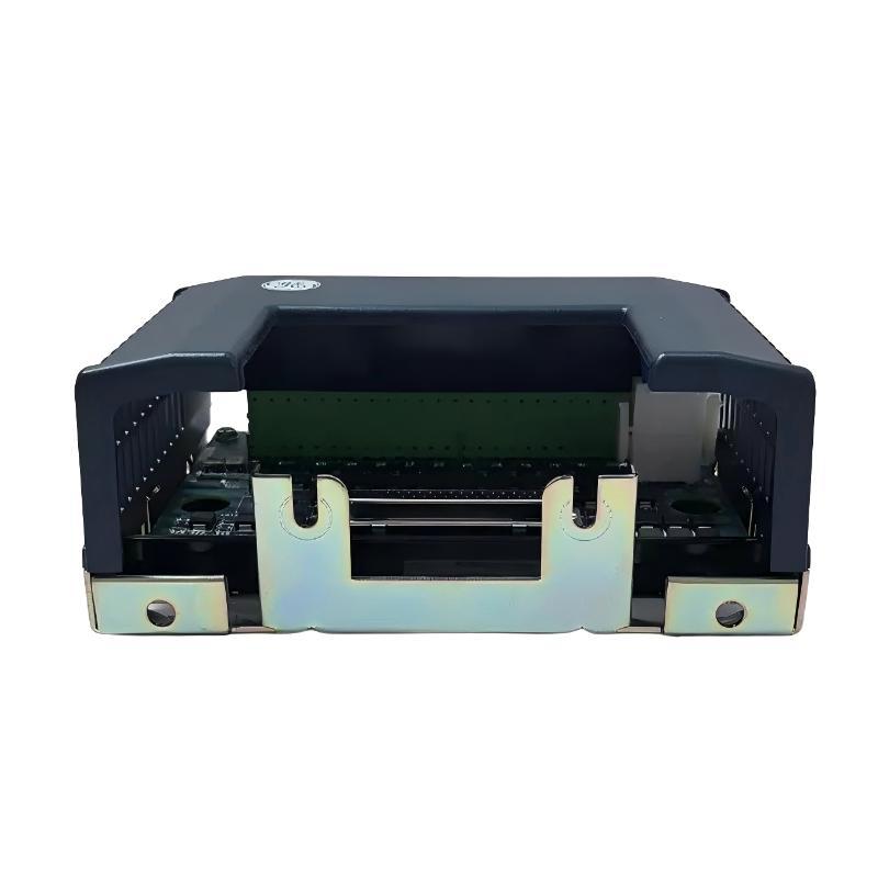
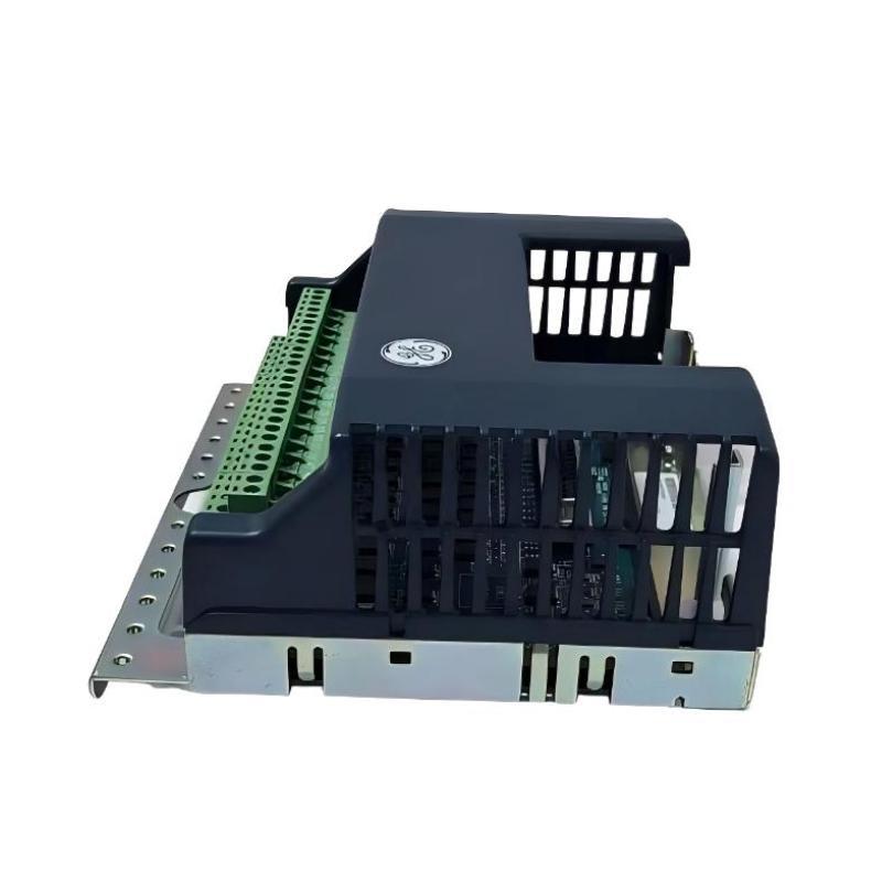
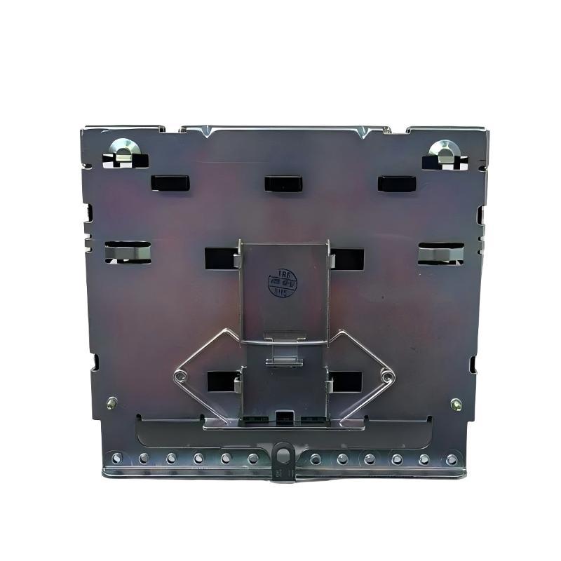
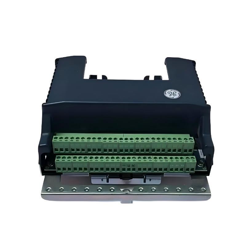
- GE
- IS410STCIS2A IS400STCIS2AFF
- Simplex Contact Input Terminal Block
- USA
- 150 × 100 × 28 mm
- 0.55 kg
- Xiamen, China
- New & In Stock
- T/T, PayPal, Western Union
- 1 Year
- 1-3 Working Days
- DHL, UPS, TNT, FedEx and EMS.
- 24-Hour Service
- COO
- 5
Our advantage

Global Logistics
We have a 10-year logistics and express cooperation agreement, so our products can be shipped to any place in the world.

Brand new and original
Our products are imported in bulk from the place of origin. Because of the cooperative relationship, our products are all original and 100% new.

24-hour service
We provide 7*24 hours service to our customers. We will be there whenever you need us.

Price advantage
All our products are priced very favorably because we have our own warehouse and supply.
| Company Information | |||
| [email protected] | |||
| Mobile | +8615980777398 | ||
| +8615980777398 | |||
| 15980777398 |
Product Overview
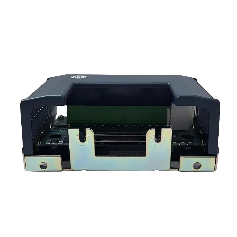
The GE IS410STCIS2A IS400STCIS2AFF Simplex Contact Input Terminal Block is an industrial control connection component intended for use in compatible GE automation systems. Contact input interfaces allow a control system to receive information from external contacts and switching devices, enabling the controller to monitor equipment status and respond to changes in field conditions. A dedicated terminal block provides organized connection points for the associated electrical circuits and supports orderly wiring within industrial control assemblies.
The product identifiers IS410STCIS2A and IS400STCIS2AFF should be verified against the installed hardware label and applicable equipment documentation to confirm the exact product configuration and compatibility. Components from the same manufacturer or product family may have similar physical characteristics while differing in terminal assignments, electrical characteristics, or intended applications.
As a simplex contact input terminal block, this product is associated with a designated contact input connection arrangement. Its specific electrical role depends on the compatible input hardware, field wiring, and host-system configuration. The terminal block should therefore be installed according to the approved wiring diagrams rather than assumptions based solely on its model designation.
The supplied dimensions are 150 × 100 × 28 mm, and the listed weight is approximately 0.55 kg. These specifications are useful for cabinet-layout planning, installation clearance checks, spare-parts management, and replacement logistics.
Technical Specifications
| Parameter | Specification |
|---|---|
| Manufacturer | General Electric (GE) |
| Primary Model | IS410STCIS2A |
| Additional Part Number | IS400STCIS2AFF |
| Product Type | Simplex Contact Input Terminal Block |
| Product Family | GE IS400 / IS410 Series identification |
| Primary Function | Contact input circuit connection interface |
| System Configuration | Simplex |
| Signal Category | Contact input |
| Application | Industrial automation and control systems |
| Interface Role | Field contact wiring connection |
| Dimensions | 150 × 100 × 28 mm |
| Weight | 0.55 kg |
| Installation | Compatible host-system mounting location |
| Input Voltage and Current | Verify against applicable hardware documentation |
| Terminal Assignment | Confirm using the approved wiring diagram |
| Compatibility | Verify the exact part number and host-system configuration |
What Is the GE IS410STCIS2A IS400STCIS2AFF?
The GE IS410STCIS2A IS400STCIS2AFF is identified as a simplex contact input terminal block. It provides a connection interface for contact input circuits within a compatible industrial control installation.
Contact input circuits are commonly used to communicate the state of external switching devices to a control system. Depending on the application, these devices may include limit switches, auxiliary contacts, push buttons, pressure switches, position contacts, and other approved devices that provide discrete electrical states.
For example, a contact may change state when a valve reaches a specified position or when a machine component activates a limit switch. The associated input hardware detects the electrical condition and makes the resulting status available to the control system.
The terminal block supports the physical wiring arrangement, while the compatible input hardware and controller perform the functions required to acquire and interpret the signal. The precise implementation depends on the installed system.
Because the product is supplied with two identifiers, technicians should confirm the relationship between IS410STCIS2A and IS400STCIS2AFF before purchasing or installing a replacement.
Understanding Contact Input Technology
A contact input allows an automation system to detect the electrical state of an external switching device. In many industrial applications, the contact represents a simple condition such as open or closed.
The input circuit detects the corresponding electrical condition and passes the resulting status to the control system through the appropriate interface hardware.
A simplified signal path is:
Field Contact → Field Wiring → Contact Input Terminal Block → Compatible Input Hardware → Controller Logic → Monitoring or Control Response
This diagram illustrates a general contact input arrangement. It does not establish the exact electrical path, terminal assignments, or internal architecture of the IS410STCIS2A.
Contact input signals can be used for monitoring, sequencing, interlocking, alarms, and equipment-status indication. Their reliability depends on the condition of the field contact, wiring integrity, terminal connections, input circuitry, and controller configuration.
Function and Working Principle
1. Field Contact Connection
The terminal block provides connection points for conductors associated with external contact devices. Correct wiring ensures that each contact signal reaches the intended input circuit.
2. Discrete Signal Transmission
A field contact changes its electrical state according to the connected device’s operation. The corresponding circuit condition is transmitted through the installed wiring to the compatible input interface.
The actual signal characteristics and wiring requirements must be confirmed from the applicable hardware documentation.
3. Input Hardware Interface
The associated contact input hardware detects the electrical state of the circuit. The controller can then use the resulting input information in its configured logic.
The terminal block should not be confused with the controller itself or assumed to contain the complete input-processing circuitry.
4. Equipment Status Monitoring
Contact input signals can provide information about the state of industrial equipment. Depending on the installation, the control system may use this information to indicate operating status, detect limit conditions, initiate alarms, or permit subsequent operations.
5. Maintenance and Fault Isolation
The terminal interface provides a physical point for checking wiring identification and connection integrity. Proper inspection helps maintenance personnel determine whether a signal problem originates in the field contact, wiring, terminal connection, input hardware, or controller configuration.
Role in Industrial Automation Systems
Modern industrial control systems depend on accurate information from field devices. Contact inputs are important because many equipment conditions are represented by discrete states rather than continuously varying measurements.
The GE IS410STCIS2A IS400STCIS2AFF serves as a contact input connection component within a compatible installation. Its contribution is associated with maintaining the physical connection between field contact circuits and the designated control-system interface.
Typical functions supported by a contact input architecture include:
- Monitoring machine or equipment status
- Detecting limit-switch operation
- Receiving auxiliary contact information
- Monitoring discrete process conditions
- Supporting alarm and indication circuits
- Providing input information for control sequences
- Supporting troubleshooting of field wiring
These are general applications of contact input systems. The specific functions available in an installation depend on the connected devices, the input hardware, and the configured control logic.
Industrial Applications
Equipment Status Monitoring
Industrial systems frequently use auxiliary contacts to indicate whether equipment is running, stopped, available, or in another defined state. A contact input arrangement allows these conditions to be monitored by the control system.
Limit-Switch Monitoring
Limit switches can indicate when a mechanical component reaches a defined position. The associated contact input circuit communicates the switch state to the controller for monitoring or sequencing.
Valve and Actuator Position Feedback
Where supported by the equipment design, discrete contacts can indicate the position or state of a valve, actuator, or other controlled mechanism. Correct field wiring is necessary to ensure that the control system receives the intended status.
Alarm and Interlock Circuits
Contact inputs may be used to receive discrete alarm conditions or interlock status. The controller can process these signals according to the approved application logic.
Safety-related functions must use appropriately designed and approved safety systems; an ordinary contact input arrangement should not automatically be treated as a safety-rated circuit.
Manufacturing and Process Automation
Manufacturing lines and process facilities use discrete input signals to monitor machine states, equipment availability, and switching conditions. A contact input terminal interface can form part of the electrical connection arrangement in compatible control installations.
Installation and System Integration
Correct installation begins with identifying the exact component and confirming its intended role within the host system.
Verify the Product Identification
Check the product label and confirm the full model designation:
- IS410STCIS2A
- IS400STCIS2AFF
Verify the relationship between these identifiers using the applicable hardware documentation. Do not assume that one designation is a direct substitute for the other without confirmation.
Review the Wiring Diagram
Use the approved electrical schematic and terminal assignment documentation to identify the correct connection points for the field contacts.
Confirm the input circuit requirements, contact arrangement, and wiring method before connecting conductors. Do not infer terminal numbering, polarity, or voltage limits from the model name.
Follow Electrical Isolation Procedures
Before installation or maintenance, apply the facility’s electrical isolation and lockout/tagout procedures. Identify all relevant power sources and confirm that the circuit is in a safe state before handling conductors or terminals.
Some field circuits may be energized independently of the main control system, so the complete electrical arrangement must be considered.
Inspect the Mounting Location
The supplied dimensions are 150 × 100 × 28 mm. Check that the intended mounting location provides sufficient space and meets the installation requirements of the host equipment.
Inspect the surrounding area for moisture, dust, corrosion, mechanical damage, and other conditions that could affect the component or its connections.
Connect and Identify Field Wiring
Inspect conductors for damaged insulation, poor termination, and unclear labels. Ensure that each field contact is wired to the correct terminal according to the approved schematic.
Maintain consistent wire identification so that future maintenance personnel can trace the circuit without ambiguity.
Verify the Installation
After installation, check the mechanical security of the terminal block and confirm the accuracy of the connections. Perform continuity checks and functional tests using the approved commissioning procedure.
Verify that the controller receives the expected contact state before returning the equipment to normal service.
Troubleshooting the GE IS410STCIS2A
Contact input faults can originate at several points in the signal path. Effective troubleshooting requires checking the field device, wiring, terminal interface, input hardware, and control logic.
1. Input Signal Not Detected
If the controller does not detect a contact transition, inspect:
- Field contact condition
- Contact wiring and conductor identification
- Terminal connection security
- Circuit power, where applicable
- Associated input hardware
- Controller input status and configuration
- Relevant system diagnostics
Compare the actual circuit arrangement with the approved schematic before making any changes.
2. Input Signal Remains Permanently On or Off
A contact input that does not change state may be caused by a faulty field switch, incorrect wiring, a broken conductor, a short circuit, a stuck mechanical contact, or an input hardware issue.
Check the field device’s mechanical operation and verify the electrical state of the circuit using the correct test procedure. Do not assume that the terminal block is defective before checking the entire signal path.
3. Intermittent Input Signal
Intermittent signals may result from loose connections, damaged cables, vibration, contact wear, corrosion, or unstable operation of the field device.
Inspect the wiring and terminal connections for visible damage. If the field contact is mechanically operated, verify that it changes state consistently under the intended operating conditions.
4. Incorrect Contact Status
If the control system reports a state that does not match the field device, check for reversed or incorrectly identified connections, an unsuitable contact arrangement, a configuration issue, or a problem with the associated input circuitry.
Use the approved wiring documentation to establish the expected signal behavior.
5. Multiple Input Problems
If several input signals fail simultaneously, consider a shared issue rather than assuming that multiple terminal connections have failed independently.
Potential areas to investigate include common wiring, shared power supplies, associated input hardware, connectors, and system-level diagnostics. The appropriate checks depend on the actual circuit design.
Preventive Maintenance Recommendations
Routine inspection helps maintain signal integrity and reduces the risk of contact input failures.
Inspect Field Contacts
Check connected switches and contact devices for mechanical damage, wear, contamination, or inconsistent operation. A defective field device may produce symptoms similar to a terminal or input hardware fault.
Inspect Wiring and Terminations
Check cables for abrasion, pinching, insulation damage, and loose identification labels. Verify that conductors remain securely connected according to the applicable maintenance instructions.
Maintain Clean Connections
Keep terminal areas free from excessive dust, moisture, corrosion, and other contamination. Follow the approved procedures when cleaning or servicing electrical components.
Monitor Input Status
Where the control system provides suitable diagnostics, periodically review input states and event records. Unexpected or intermittent changes may indicate developing problems with a field device or its wiring.
Maintain Service Records
Record inspection findings, wiring changes, replacement details, and functional test results. Accurate maintenance records help identify recurring problems and support future troubleshooting.
Compatible System Components
The IS410STCIS2A IS400STCIS2AFF should be evaluated as part of the complete control-system installation. Depending on the actual configuration, associated equipment may include the following component categories.
| Component Category | Typical Function |
|---|---|
| Field Contact Device | Provides an open/closed or other discrete contact state |
| Field Wiring | Carries the contact circuit to the control equipment |
| Contact Input Terminal Block | Provides organized electrical connection points |
| Compatible Input Hardware | Detects the electrical state of the input circuit |
| Industrial Controller | Processes input information using configured logic |
| Power Supply | Provides power to designated system components or circuits |
| Operator Interface | Displays equipment status and alarms |
| Engineering Documentation | Defines terminal assignments, wiring, and configuration |
This table describes general functional categories and does not establish compatibility with specific GE module part numbers. Confirm all hardware relationships against the documentation for the installed system.
Replacement and Procurement Considerations
Selecting a replacement contact input terminal block requires verification of the complete product identification and its electrical role.
Before purchasing or installing a replacement, confirm:
- Full model and part number
- Relationship between IS410STCIS2A and IS400STCIS2AFF
- Manufacturer and product-label details
- Revision information, where applicable
- Terminal arrangement and connection layout
- Associated contact input hardware
- Host-system compatibility
- Electrical characteristics and circuit requirements
- Mounting dimensions and available clearance
- Approved installation and commissioning procedures
The supplied dimensions of 150 × 100 × 28 mm and weight of 0.55 kg are useful for enclosure planning, inventory management, and shipping preparation. They do not, by themselves, establish electrical compatibility or interchangeability.
For critical control installations, have the proposed replacement verified by the responsible engineering or maintenance team before installation.
Key Advantages
Organized Contact Input Connections
The terminal interface supports structured wiring for contact input circuits within a compatible control installation.
Support for Discrete Status Monitoring
When used with appropriate input hardware, contact circuits can communicate equipment states to the control system.
Easier Inspection and Troubleshooting
Organized terminal connections help technicians inspect wiring and trace potential faults through the signal path.
Practical Installation Planning
The supplied dimensions of 150 × 100 × 28 mm support cabinet-layout preparation and replacement planning.
Efficient Spare-Parts Management
The model identifiers and listed weight of 0.55 kg help support inventory identification, procurement, and maintenance logistics.
Technical FAQs
What is the GE IS410STCIS2A IS400STCIS2AFF?
It is identified as a GE Simplex Contact Input Terminal Block intended for use in compatible industrial control equipment. Its precise electrical role should be confirmed from the applicable system documentation.
What is a contact input terminal block used for?
It provides connection points for wiring from external contact devices to a compatible control-system input arrangement. The input hardware detects the contact state, and the controller uses the resulting information according to its configuration.
What are the dimensions of this product?
The supplied dimensions are 150 × 100 × 28 mm.
How much does the product weigh?
The supplied weight is approximately 0.55 kg.
Are IS410STCIS2A and IS400STCIS2AFF interchangeable?
Interchangeability should not be assumed from the two identifiers alone. Verify the exact product configuration, terminal arrangement, and host-system requirements before selecting a replacement.
What can cause a contact input signal to fail?
Possible causes include a defective field contact, loose connections, damaged wiring, incorrect terminal assignments, a fault in the associated input hardware, or an issue with the controller configuration.
Can this terminal block directly process input signals?
A terminal block primarily provides an electrical connection interface. Signal detection and processing generally depend on the associated input hardware and control system.
How should the terminal block be maintained?
Maintenance should include inspection of the component, wiring, terminal connections, and connected field contacts. Follow approved electrical safety procedures and verify circuit operation after servicing.
Conclusion
The GE IS410STCIS2A IS400STCIS2AFF Simplex Contact Input Terminal Block is an industrial connection component intended to support contact input wiring in compatible GE control installations. By providing organized connection points, it can contribute to reliable signal routing, equipment-status monitoring, and efficient maintenance of industrial automation systems.
With supplied dimensions of 150 × 100 × 28 mm and a weight of 0.55 kg, the component can be included in cabinet-layout planning and industrial spare-parts management.
Before installation or replacement, confirm the exact part designation, terminal assignments, and host-system compatibility. Correct wiring, appropriate electrical isolation, inspection of connected field devices, and functional verification are essential for maintaining reliable contact input operation.