

ProductPRODUCT
Featured products



Contact Us
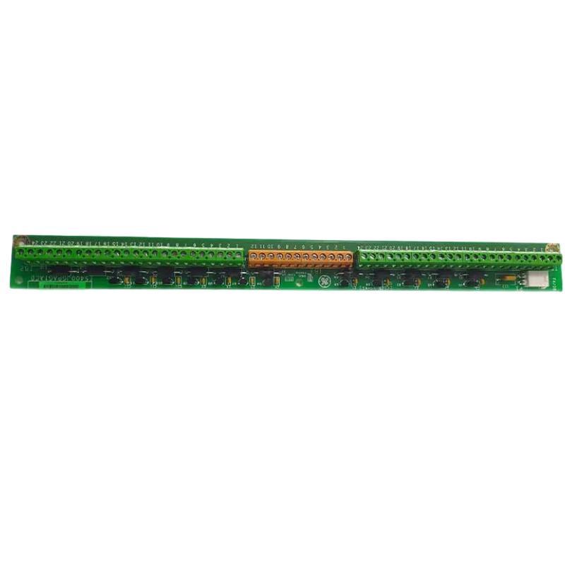
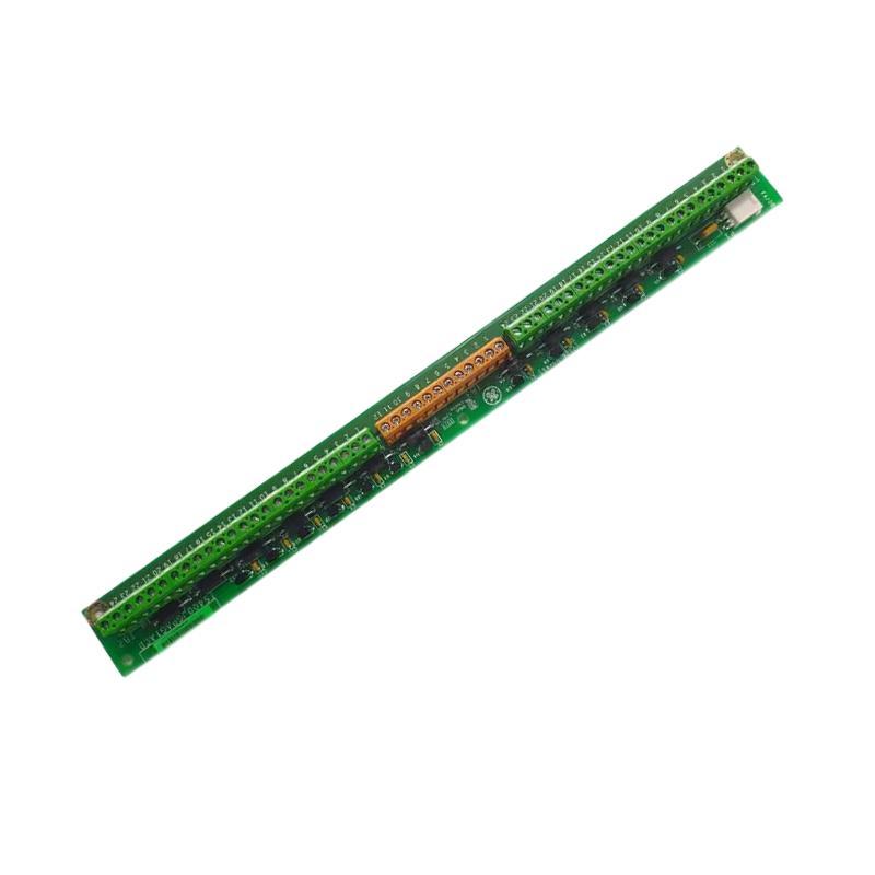
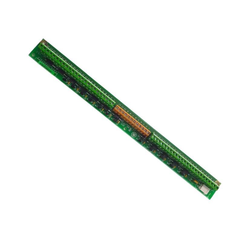
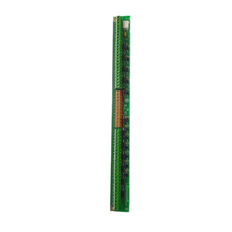
- GE
- IS400JGPAG1A
- Grounding Terminal Block
- USA
- 320 × 250 × 30 mm
- 1.25 kg
- Xiamen, China
- New & In Stock
- T/T, PayPal, Western Union
- 1 Year
- 1-3 Working Days
- DHL, UPS, TNT, FedEx and EMS.
- 24-Hour Service
- COO
- 23
Our advantage

Global Logistics
We have a 10-year logistics and express cooperation agreement, so our products can be shipped to any place in the world.

Brand new and original
Our products are imported in bulk from the place of origin. Because of the cooperative relationship, our products are all original and 100% new.

24-hour service
We provide 7*24 hours service to our customers. We will be there whenever you need us.

Price advantage
All our products are priced very favorably because we have our own warehouse and supply.
| Company Information | |||
| [email protected] | |||
| Mobile | +8615980777398 | ||
| +8615980777398 | |||
| 15980777398 |
Product Overview
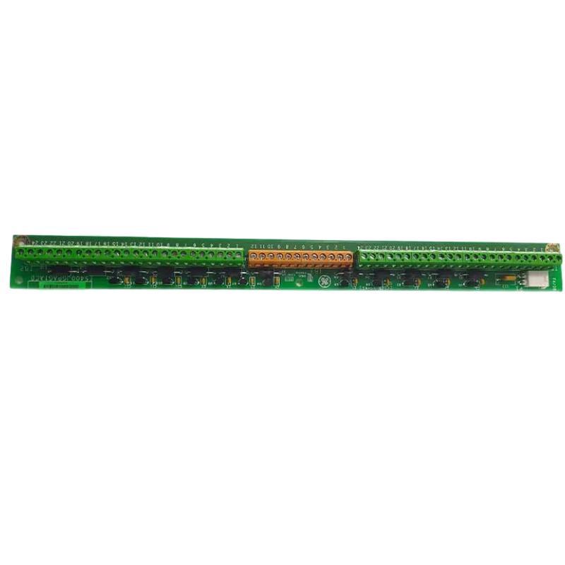
The GE IS400JGPAG1A Grounding Terminal Block is an industrial electrical component intended for grounding-related connections within a compatible control system. Grounding components play an important role in industrial automation by providing designated connection points for protective earth conductors, grounding conductors, or other grounding arrangements specified by the equipment design. Correct grounding practices help support electrical safety, reduce the risk associated with unintended electrical potentials, and improve the reliability of industrial control installations.
In industrial environments, grounding is particularly important because control cabinets may contain programmable controllers, electronic interface boards, power supplies, signal-conditioning devices, communication equipment, and field wiring. A properly designed grounding arrangement helps establish the intended electrical reference and provides a controlled path for fault current where required by the system design.
The GE IS400JGPAG1A is listed with dimensions of 320 × 250 × 30 mm and a weight of approximately 1.25 kg. These physical specifications are useful for cabinet-layout planning, spare-parts management, equipment identification, and replacement logistics.
The exact electrical configuration, terminal count, conductor capacity, grounding resistance requirements, and mounting arrangement of this model should be verified against the applicable equipment documentation. Grounding components that appear similar may have different connection designs or electrical ratings, so the full part number should be confirmed before installation or replacement.
Technical Specifications
| Parameter | Specification |
|---|---|
| Manufacturer | General Electric (GE) |
| Model Number | IS400JGPAG1A |
| Product Type | Grounding Terminal Block |
| Product Series | GE IS400 Series |
| Primary Function | Grounding connection and electrical bonding, subject to system design |
| Application | Industrial control and electrical installations |
| Terminal Count | Verify from the applicable product documentation |
| Conductor Size Range | Verify from the applicable product documentation |
| Electrical Rating | Verify from the applicable product documentation |
| Grounding Arrangement | Confirm from the host equipment design |
| Mounting Method | Verify from the product documentation |
| Dimensions | 320 × 250 × 30 mm |
| Weight | 1.25 kg |
| Installation Environment | Compatible industrial control equipment |
| Replacement Requirement | Confirm part number, revision, terminal arrangement, and electrical compatibility |
Note: Dimensions and weight are based on the supplied product information. Electrical ratings, terminal configuration, conductor capacity, and specific system compatibility should be confirmed before installation.
What Is the GE IS400JGPAG1A Grounding Terminal Block?
A grounding terminal block is a connection component used to organize and secure grounding conductors within an electrical or industrial control installation. It provides designated connection points that allow conductors to be connected according to the grounding and bonding arrangement established by the equipment designer.
Unlike ordinary signal terminals, grounding terminals are associated with the electrical reference or protective grounding system. Their function depends on the installation. A grounding terminal may be used as part of a protective earth arrangement, an equipment-bonding network, or another specified grounding connection.
The GE IS400JGPAG1A is identified as a grounding terminal block. Its precise role within a particular GE control platform should be established from the installed assembly and relevant technical documentation rather than inferred solely from the model number.
Grounding components are often integrated into larger electrical assemblies that include control boards, power distribution hardware, terminal blocks, and cabinet grounding conductors. The terminal block itself is only one element of the overall grounding arrangement. Reliable performance depends on correct conductor selection, secure connections, suitable mounting, and compliance with the applicable electrical design.
Function and Working Principle
1. Providing Designated Grounding Connections
The primary purpose of a grounding terminal block is to provide an organized location for grounding conductors. Designated connection points help technicians establish and maintain the intended grounding arrangement.
The number and type of connections supported by the IS400JGPAG1A should be confirmed from its physical layout and technical documentation.
2. Supporting Electrical Bonding
Electrical bonding connects conductive parts according to the installation’s grounding design. Where required, bonding helps keep accessible conductive components at an appropriate common potential and provides a path for fault current through the designated protective circuit.
A terminal block may form part of this bonding arrangement when its construction, rating, and installation are suitable for that purpose.
3. Organizing Grounding Conductors
Industrial cabinets may contain multiple grounding conductors associated with equipment frames, enclosure panels, cable shields, or designated grounding points. The actual connections must follow the system’s electrical design.
A properly organized terminal arrangement can make inspection and maintenance easier by helping technicians identify conductors and verify their connections.
4. Supporting Electrical Safety
Protective grounding is an important part of an electrical safety system. Where the grounding arrangement is correctly designed and installed, it helps provide a controlled path for fault current so that appropriate protective devices can operate.
A grounding terminal block does not provide complete protection by itself. Overall safety also depends on suitable conductors, protective devices, bonding connections, enclosure design, and correct installation practices.
5. Supporting Reliable Control-System Operation
Industrial control equipment can be sensitive to electrical interference and differences in electrical potential. A properly implemented grounding and bonding system can help reduce certain electrical noise problems and support consistent system operation.
However, protective earth, signal reference, and cable-shield connections serve different purposes. They should not be interconnected indiscriminately. The connection method must follow the grounding strategy specified for the control system.
Role in Industrial Control Systems
Within a GE industrial control installation, the IS400JGPAG1A Grounding Terminal Block may serve as part of the grounding arrangement associated with the host equipment. Its contribution depends on how the terminal block is incorporated into the complete cabinet or control assembly.
A typical industrial control cabinet may contain:
- Programmable controllers and control electronics
- Input and output interface modules
- Power distribution components
- Communication interfaces
- Signal and power wiring
- Protective grounding conductors
- Enclosure bonding connections
- Field-device interfaces
These components may require different grounding or reference arrangements. Protective grounding is intended to support electrical safety, while signal grounding and cable shielding may be used to manage electrical reference and electromagnetic interference.
The installation should therefore maintain a clear distinction between protective earth, functional grounding, signal reference, and shield termination. The exact arrangement depends on the equipment architecture and applicable electrical requirements.
For maintenance teams, the grounding terminal block is important because a loose, corroded, incorrectly connected, or unsuitable grounding connection can affect the safety and reliability of the overall installation.
Industrial Applications
Industrial Automation Cabinets
Industrial automation cabinets contain control hardware, electrical distribution components, wiring terminals, and interfaces to field devices. Grounding terminal blocks can help organize designated grounding connections within a properly designed cabinet.
The mounting location and conductor arrangement should follow the cabinet’s electrical drawings and equipment instructions.
Power Distribution Assemblies
Electrical distribution assemblies require grounding and bonding arrangements appropriate to their voltage levels, protective devices, enclosure construction, and installation environment. A suitable terminal block may form part of the designated grounding network.
Its suitability must be confirmed against the required electrical rating and conductor specifications.
PLC and Control-System Installations
PLC-based control systems combine electronic hardware with field wiring and power distribution. A properly designed grounding arrangement supports electrical safety and may help reduce interference affecting control signals.
The grounding terminal block should be installed only in the location and configuration specified for the particular system.
Industrial Machinery
Industrial machines commonly include metal frames, control enclosures, motors, drives, sensors, and actuator wiring. Protective bonding may be required between conductive components to maintain the intended electrical safety arrangement.
The grounding terminal block can be considered as part of this broader arrangement when it is approved for the application.
Process Automation Facilities
Process facilities often operate distributed instrumentation and control equipment in environments where reliable operation and maintainability are important. Organized grounding connections can help technicians inspect and maintain the electrical installation.
The grounding design must also account for the specific environmental and electrical requirements of the facility.
Maintenance and Equipment Replacement
Grounding terminal blocks may be inspected during planned maintenance, cabinet refurbishment, or replacement of damaged components. Correct identification is particularly important because terminal arrangement, conductor capacity, and electrical ratings can differ between products.
Installation and System Integration
Correct installation of the GE IS400JGPAG1A requires confirmation of the product’s intended role and compliance with the grounding design of the host equipment.
1. Verify the Product Identification
Before installation or replacement, confirm the complete part number IS400JGPAG1A and compare the component with the installed hardware.
Record the following details where available:
- Complete model number
- Hardware revision or additional identification markings
- Existing mounting location
- Terminal arrangement
- Conductor routing
- Associated grounding conductors
- Host equipment and cabinet identification
Do not select a replacement based solely on a similar appearance or matching dimensions.
2. Review the Grounding Design
Consult the applicable electrical drawings and installation instructions to determine the intended function of each connection. Confirm whether the terminal block is used for protective grounding, bonding, or another designated grounding purpose.
Do not assume that all grounding conductors or cable shields can share the same terminal. Their connection points should be determined by the equipment design.
3. Isolate the Equipment Safely
Before performing maintenance, follow the site’s electrical safety procedures and applicable lockout/tagout requirements. Isolate relevant energy sources and verify that the equipment is in a safe condition before handling conductors.
Grounding components can be associated with hazardous electrical circuits. Installation and inspection should be performed by qualified personnel using appropriate safety practices.
4. Inspect the Mounting Surface
Check the designated mounting location for physical damage, contamination, corrosion, loose hardware, or other conditions that could affect the connection.
The listed dimensions are 320 × 250 × 30 mm. Confirm that the available space accommodates the component and allows adequate access for conductor routing, inspection, and maintenance.
5. Check the Conductors
Verify that each grounding conductor is suitable for its intended purpose and complies with the applicable conductor-size requirements. Inspect the insulation, conductor condition, terminal hardware, and connection surfaces.
Do not assume that a conductor suitable for one grounding terminal is automatically suitable for another. Conductor size, terminal capacity, and connection method must be compatible.
6. Secure the Connections
Install conductors according to the manufacturer’s specified connection method and tightening requirements. If a torque value is required, obtain it from the applicable documentation rather than estimating it.
An inadequately secured connection can increase contact resistance, overheat under fault conditions, or become unreliable over time.
7. Verify Electrical Continuity
Following installation, qualified personnel should verify the grounding and bonding arrangement using the approved test method for the system. Testing should confirm the required connections without introducing unsafe conditions or damaging sensitive electronics.
The acceptable results depend on the grounding design, conductor path, and applicable electrical standards.
8. Complete Final Inspection
Before returning the equipment to service, check that conductors are correctly identified, terminals are secure, and no wiring has been displaced or damaged.
Confirm that the completed installation matches the electrical drawings and that any required inspection or test results have been recorded.
Troubleshooting the GE IS400JGPAG1A
Grounding problems should be investigated as part of the complete electrical installation. The terminal block may be involved, but the cause can also be related to wiring, corrosion, mounting, bonding conductors, or other parts of the grounding network.
Loose Grounding Connection
A loose connection can reduce the reliability of the grounding path and may cause intermittent electrical problems.
Potential causes include:
- Insufficient tightening
- Incorrect connection hardware
- Mechanical vibration
- Conductor movement
- Improper installation
- Deterioration of the terminal or conductor
The equipment should be placed in a safe state before inspection. Connections should be checked and restored according to the specified installation procedure.
Corrosion or Contamination
Corrosion, dust, moisture, or chemical contamination may affect conductive surfaces and connection integrity.
Inspect the terminal block and surrounding area for visible deterioration. If damage is present, determine whether the terminal block, conductor, mounting surface, or environmental protection requires corrective action.
Do not simply clean and reuse a damaged component if its electrical integrity can no longer be assured.
Unexpected Electrical Noise
Electrical interference may sometimes be associated with grounding or shielding problems. However, noise can also originate from switching equipment, cable routing, poor shielding termination, unsuitable signal wiring, or incorrect system configuration.
Check the grounding design and cable routing before modifying connections. Avoid making unapproved links between protective earth, signal reference, and cable shields, as these changes can introduce new problems.
Intermittent Equipment Faults
Intermittent faults may occur when grounding or bonding connections are loose, corroded, or mechanically unstable. Similar symptoms can also result from power-supply problems, damaged cables, or defective electronic components.
Review fault records and inspect the complete electrical path. If an intermittent grounding issue is suspected, use an approved test procedure to identify the actual source rather than replacing the terminal block without verification.
Failed Grounding Continuity Test
A failed continuity test requires investigation of the complete path between the specified grounding points.
Check the conductor, terminal interface, mounting connection where applicable, and associated bonding points. Confirm that the test method and measurement points are appropriate for the intended grounding arrangement.
Any corrective work should be followed by the required verification test before the equipment returns to service.
Maintenance Recommendations
Routine inspection helps preserve the reliability of grounding connections and reduces the likelihood of undetected deterioration.
Periodic Visual Inspection
Inspect the terminal block for cracks, deformation, corrosion, discoloration, contamination, and signs of overheating. Investigate any unusual condition before it develops into a more serious electrical problem.
Connection Integrity Checks
Check the condition of the connected conductors and terminal hardware during scheduled maintenance. Tightening and reconnection work should follow the specified procedure and torque requirements.
Grounding Continuity Verification
Where required by the maintenance plan, verify grounding and bonding continuity using an appropriate test method. Record the test points, results, and any corrective actions.
Environmental Protection
Maintain suitable cabinet conditions and protect the component from moisture, corrosive substances, and excessive contamination. The required environmental protection depends on the actual installation.
Conductor Identification
Ensure that grounding conductors remain correctly identified and routed. Clear labeling can simplify inspection, replacement, and troubleshooting.
Maintenance Documentation
Record the part number, installation location, inspection date, observed condition, and test results. Documentation supports traceability and helps maintenance teams identify recurring problems.
Compatible System Components
A grounding terminal block may form part of a larger electrical assembly containing several types of equipment.
| Component Category | Typical Function |
|---|---|
| Grounding Conductors | Connect designated grounding points |
| Protective Earth Network | Provides the intended protective grounding path |
| Bonding Conductors | Connect conductive parts according to the electrical design |
| Industrial Control Cabinet | Houses and protects electrical and control equipment |
| PLC and Control Hardware | Executes or supports automation functions |
| Power Distribution Components | Distribute electrical power to connected equipment |
| I/O Modules | Interface with field signals |
| Signal and Communication Cables | Carry control and data signals |
| Cable Shield Terminations | Connect shields according to the specified EMC design |
| Protective Devices | Provide protection appropriate to the electrical installation |
These are general component categories, not a verified list of specific parts compatible with the IS400JGPAG1A. The exact connections and supported equipment must be confirmed from the host-system documentation.
Replacement and Procurement Considerations
Selecting the correct grounding terminal block is important because grounding components must match the electrical and mechanical requirements of the installation.
When purchasing the GE IS400JGPAG1A, consider the following points:
- Exact part number: Verify that the required model is IS400JGPAG1A.
- Physical dimensions: Confirm the listed size of 320 × 250 × 30 mm against the available installation space.
- Weight: Use the listed weight of 1.25 kg for handling and shipping preparation.
- Terminal arrangement: Compare the connection layout with the installed component.
- Conductor capacity: Confirm the supported conductor sizes and connection methods.
- Electrical suitability: Verify that the component meets the requirements of the intended grounding arrangement.
- Mounting configuration: Check the specified mounting method and mechanical interface.
- Hardware condition: Inspect the component for damage, corrosion, deformation, or signs of previous overheating.
- System compatibility: Confirm that the component is intended for the actual host equipment and installation.
A substitute should not be approved merely because its dimensions are similar. Grounding components must be evaluated for their intended electrical function and connection requirements.
Key Advantages
Organized Grounding Connections
A designated grounding terminal block can help arrange grounding conductors and make the electrical installation easier to inspect.
Support for Electrical Safety
When selected and installed correctly, grounding hardware can contribute to the protective grounding and bonding arrangement of an industrial control system.
Improved Maintenance Accessibility
Clearly arranged grounding connections can make inspection, continuity testing, and fault investigation more systematic.
Practical Installation Information
The listed dimensions of 320 × 250 × 30 mm and weight of 1.25 kg support cabinet planning, handling, and inventory management.
Integration Into Industrial Electrical Assemblies
The IS400JGPAG1A can be evaluated for use in a compatible industrial control installation after its precise function and electrical requirements have been confirmed.
Technical FAQs
What is the GE IS400JGPAG1A?
The GE IS400JGPAG1A is identified as a Grounding Terminal Block for industrial electrical and control-system applications. Its exact connection arrangement should be verified from the applicable technical documentation.
What are the dimensions of the IS400JGPAG1A?
The listed dimensions are 320 × 250 × 30 mm.
What is the weight of the GE IS400JGPAG1A?
The listed weight is approximately 1.25 kg.
What is the purpose of a grounding terminal block?
A grounding terminal block provides designated connection points for grounding conductors within an electrical installation. Depending on the design, it may form part of a protective grounding or bonding arrangement.
Can a grounding terminal block eliminate electrical noise?
Not by itself. Correct grounding and shielding can help reduce certain interference problems, but noise may also be caused by cable routing, switching equipment, wiring faults, or signal configuration. The complete installation should be evaluated.
How should the IS400JGPAG1A be installed?
Installation should follow the approved electrical drawings and applicable equipment instructions. Qualified personnel should verify conductor suitability, terminal connections, mounting, and grounding continuity before returning the equipment to service.
What should be checked if grounding continuity is poor?
Inspect the complete grounding path, including the conductor, terminal connection, associated bonding points, and mounting interface where applicable. Use an approved test procedure to identify the cause.
Can another terminal block replace the IS400JGPAG1A?
Interchangeability should not be assumed. The replacement must meet the required electrical function, conductor capacity, terminal configuration, mounting requirements, and host-system specifications.
Why is regular inspection important?
Regular inspection can identify loose connections, corrosion, damaged conductors, and other conditions that may compromise the grounding arrangement. Scheduled verification also helps maintain accurate maintenance records.
Conclusion
The GE IS400JGPAG1A Grounding Terminal Block is an industrial electrical component intended for grounding-related connections within a compatible control installation. Grounding terminal blocks help organize designated conductor connections and can contribute to the protective grounding and bonding arrangement when correctly selected and installed.
With listed dimensions of 320 × 250 × 30 mm and a weight of 1.25 kg, the component can be assessed for cabinet planning, maintenance inventory, and replacement logistics. Its suitability, however, depends on the exact electrical design, terminal configuration, conductor requirements, and host-system compatibility.
For dependable operation, maintenance teams should verify the complete model designation, inspect the grounding connections, follow the approved installation procedure, and perform the required continuity checks. Correct component identification and systematic maintenance help support electrical safety and reliable operation of industrial automation equipment.