

ProductPRODUCT
Featured products



Contact Us
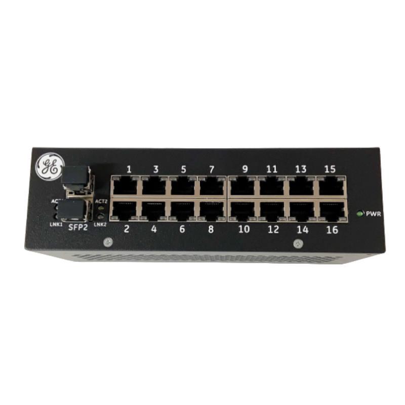
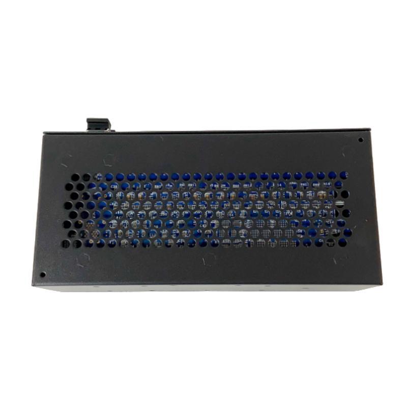
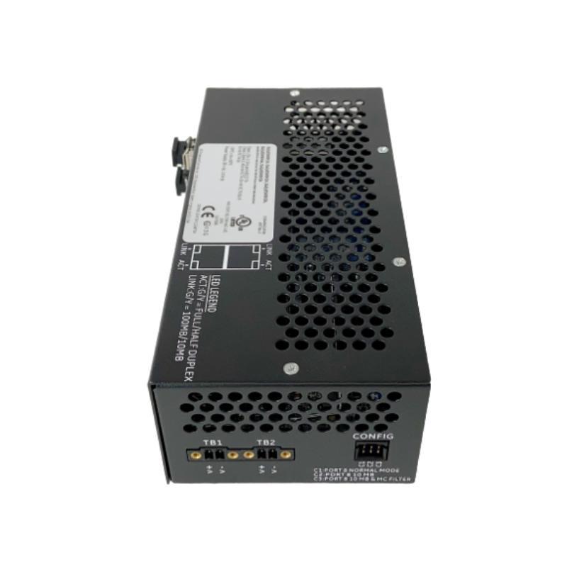
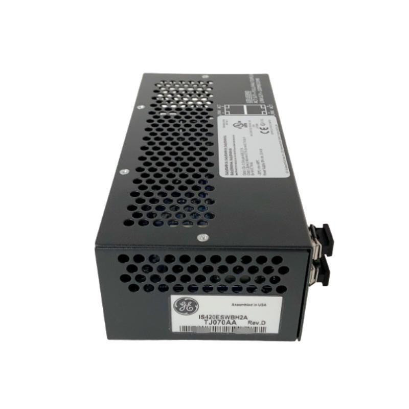
- GE
- IS400AEBMH3A
- Programmable Logic Controller
- USA
- 230 × 160 × 100 mm
- 1.4 kg
- Xiamen, China
- New & In Stock
- T/T, PayPal, Western Union
- 1 Year
- 1-3 Working Days
- DHL, UPS, TNT, FedEx and EMS.
- 24-Hour Service
- COO
- 15
Our advantage

Global Logistics
We have a 10-year logistics and express cooperation agreement, so our products can be shipped to any place in the world.

Brand new and original
Our products are imported in bulk from the place of origin. Because of the cooperative relationship, our products are all original and 100% new.

24-hour service
We provide 7*24 hours service to our customers. We will be there whenever you need us.

Price advantage
All our products are priced very favorably because we have our own warehouse and supply.
| Company Information | |||
| [email protected] | |||
| Mobile | +8615980777398 | ||
| +8615980777398 | |||
| 15980777398 |
Product Overview
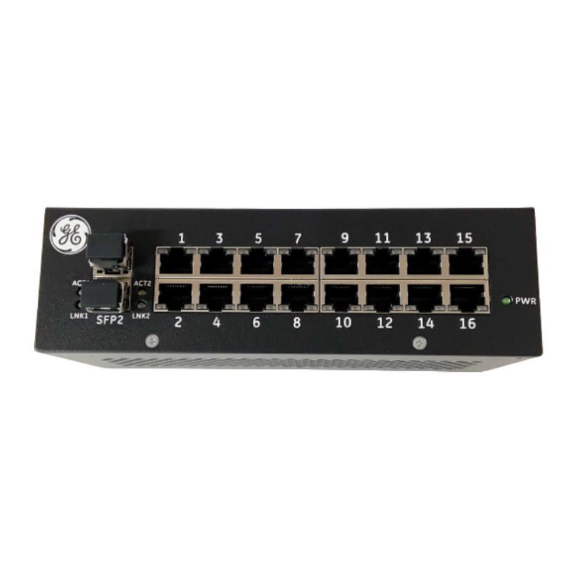
The GE IS400AEBMH3A Programmable Logic Controller (PLC) is an industrial automation component identified by its GE IS400 series part number. Programmable logic controllers are used in industrial environments to execute control logic, coordinate equipment operation, process input information, and support automated production and process-management tasks. In a suitable control architecture, a PLC-related component can contribute to reliable coordination between field devices, control electronics, and the wider automation system.
The GE IS400AEBMH3A is listed with dimensions of 230 × 160 × 100 mm and a weight of approximately 1.4 kg. These physical specifications are useful for equipment identification, cabinet-layout planning, inventory management, shipping preparation, and replacement planning.
For industrial buyers and maintenance teams, identifying the correct hardware is essential. The complete model number should be recorded and checked against the installed equipment before a replacement is ordered. Although the product is described as a programmable logic controller, its precise hardware role, processor architecture, I/O capacity, communication interfaces, and supported control platform should be confirmed from the equipment nameplate and applicable technical documentation.
In industrial automation applications, correctly matched control hardware helps maintenance teams preserve system configuration, reduce unnecessary downtime, and maintain consistent operation across interconnected equipment. The IS400AEBMH3A should therefore be evaluated according to the requirements of its intended installation rather than by physical appearance alone.
Technical Specifications
| Parameter | Specification |
|---|---|
| Manufacturer | General Electric (GE) |
| Model Number | IS400AEBMH3A |
| Product Type | Programmable Logic Controller |
| Product Series | GE IS400 Series |
| Primary Application | Industrial automation and control |
| Control Function | To be confirmed for the installed hardware configuration |
| Processor Type | Verify from applicable technical documentation |
| I/O Capacity | Verify from the product documentation |
| Communication Interfaces | Verify from the product documentation |
| Power Requirements | Verify from the equipment nameplate and technical documentation |
| Installation | Compatible industrial control equipment |
| Dimensions | 230 × 160 × 100 mm |
| Weight | 1.4 kg |
| Operating Environment | Must comply with the specified equipment requirements |
| Replacement Requirement | Confirm full model number, hardware revision, and system compatibility |
Note: Only the product identity, category, dimensions, and weight listed above are treated as established specifications. Electrical ratings, processor features, interface types, and detailed compatibility should be verified before installation.
What Is the GE IS400AEBMH3A?
A programmable logic controller is an industrial control device designed to execute a defined control program. It receives information from connected devices, evaluates programmed conditions, and coordinates the operation of equipment through appropriate control interfaces.
PLCs are widely used because industrial processes often require repeatable control sequences, predictable responses to field signals, and the ability to adapt operating logic when production requirements change. Depending on the controller architecture, a PLC-based system may manage discrete operations, coordinate machinery, monitor process conditions, or exchange information with other automation equipment.
The GE IS400AEBMH3A is identified for this application category. Its exact role within a particular installation must be established by confirming the host system and the board or module identification. The model number alone should not be used to infer a specific processor family, programming environment, communication protocol, or number of supported I/O points.
When assessing this product, engineers should distinguish between the controller itself and the complete automation system. A PLC-based installation may include a processor, power supply, I/O modules, communication interfaces, field wiring, operator panels, and supervisory software. These elements work together, but their individual functions and compatibility requirements are different.
Function and Working Principle
1. Acquisition of Input Information
Industrial control systems obtain information from field devices such as limit switches, proximity sensors, pressure transmitters, temperature instruments, and other monitoring equipment. The signals indicate the condition of machinery or the process being controlled.
A PLC-based system uses compatible input hardware to make this information available to the control logic. The exact input types supported by a particular installation depend on the selected I/O modules and system configuration.
2. Execution of Control Logic
The control program defines how the system should respond to incoming information. Typical logic may include interlocks, operating sequences, permissive conditions, alarms, and equipment-start or equipment-stop commands.
The controller evaluates the configured logic and determines the appropriate response. This allows industrial equipment to operate according to established process requirements rather than relying entirely on manual intervention.
3. Coordination of Outputs
After evaluating the control logic, the system sends commands through compatible output interfaces. These commands may control contactors, valves, indicator devices, motor-control equipment, or other actuators, depending on the installation.
The output hardware must be suitable for the connected load. Voltage, current, switching characteristics, and electrical isolation requirements should be checked before connecting field equipment.
4. Communication With Other Equipment
Many industrial control architectures exchange data between controllers, remote I/O stations, operator interfaces, and supervisory systems. Such communication can support status monitoring, alarm handling, production coordination, and maintenance activities.
The communication capabilities of the IS400AEBMH3A should be verified for the specific hardware version and host system. A protocol or network interface should not be assumed unless it is confirmed by the applicable documentation.
5. Monitoring and Fault Response
A properly configured control system can use diagnostic information to identify abnormal conditions, including missing input signals, communication interruptions, equipment interlocks, or control-system faults.
The available diagnostic functions depend on the controller architecture and connected devices. Maintenance personnel should use the relevant system indicators and diagnostic tools when investigating a problem rather than assuming that every fault originates from the controller.
Role in Industrial Automation Systems
The GE IS400AEBMH3A can be evaluated as part of an industrial automation architecture in which control hardware supports the coordination of machines, field signals, and process equipment.
A typical PLC-based arrangement may follow this functional sequence:
Field Devices → Input Interfaces → Control Logic → Output Interfaces → Industrial Equipment
Operator interfaces and supervisory systems may also exchange information with the control architecture where supported.
Within such an arrangement, the main purpose of programmable control is to provide repeatable operation and consistent execution of established process logic. The controller-based architecture can help reduce manual intervention, improve operating consistency, and make troubleshooting more systematic.
For maintenance engineers, the most important consideration is the relationship between the installed hardware and the existing control program. Replacing a controller-related component with an incorrectly matched unit may affect configuration, communications, field signal handling, or equipment operation. Hardware compatibility should therefore be established before a replacement is installed.
Industrial Applications
PLC-based control systems are used across a wide range of industries. The following examples describe general application areas for compatible programmable control equipment; they do not confirm that every application is supported by the IS400AEBMH3A in isolation.
Manufacturing and Production Lines
Automated production lines use control logic to coordinate equipment sequences, monitor machine states, manage interlocks, and synchronize related operations. A suitable controller architecture can help improve repeatability and simplify fault investigation.
Material Handling Systems
Conveyors, transfer mechanisms, sorting equipment, and automated handling stations frequently require coordinated control of motors, sensors, and actuators. PLC-based systems can execute movement sequences and respond to equipment status signals.
Industrial Machinery
Manufacturing machines may rely on programmable control for operating sequences, safety-related interlocks, machine status monitoring, and production-cycle coordination. The controller and associated interfaces must be selected according to the machine’s electrical and operational requirements.
Process Automation
Industrial processes often involve multiple instruments, valves, pumps, and other equipment. A compatible control architecture can coordinate process steps and provide operating information to local or supervisory interfaces.
Utilities and Infrastructure
Water systems, industrial utilities, and facility equipment may use PLC-based control to manage operating sequences and monitor equipment conditions. Suitability depends on the requirements of the application and the specifications of the complete installed system.
Equipment Modernization and Maintenance
Industrial facilities may need to replace aging control hardware, restore an existing installation, or maintain spare units for planned shutdowns. In these cases, exact model identification and compatibility verification are particularly important.
Installation and System Integration
Correct installation begins with confirming the product identity and the requirements of the host equipment. The following procedure provides a general framework for qualified industrial maintenance personnel.
Step 1: Verify the Product Identification
Before installation, compare the new unit with the existing equipment. Confirm:
- Complete model number: IS400AEBMH3A
- Manufacturer and product identification
- Hardware revision, where applicable
- Connector arrangement and physical layout
- Existing mounting position
- Associated modules and interface hardware
- Host-system requirements
If the existing unit has additional identification labels or revision markings, record these details before removing it.
Step 2: Review the Host-System Requirements
Confirm the controller architecture in which the product is intended to operate. Verify the required power supply, mounting method, connector assignments, supported modules, and any hardware configuration requirements.
Do not rely solely on a similar-looking module or a related part number as evidence of compatibility. Products within the same manufacturer family can serve different functions and may not be interchangeable.
Step 3: Isolate the Equipment Safely
Before working inside an industrial control cabinet, follow the facility’s electrical safety procedures and the equipment manufacturer’s instructions. Isolate relevant energy sources, apply lockout/tagout procedures where required, and verify that the equipment is in a safe state.
Stored energy and externally powered circuits may remain hazardous even when the main supply has been disconnected. Only qualified personnel should perform the installation.
Step 4: Inspect the Installation Area
Check the cabinet and mounting location for contamination, moisture, excessive heat, vibration, loose hardware, or signs of electrical damage.
The listed dimensions of 230 × 160 × 100 mm should be considered when checking the available installation space. Additional clearance may be required for connectors, wiring bends, ventilation, access, and maintenance.
Step 5: Check Connections and Wiring
Inspect connectors and associated wiring before reconnecting the hardware. Confirm that terminals, cables, and interfaces match the documented configuration.
Avoid changing wiring assignments based only on connector shape or physical similarity. Incorrect connections may damage equipment or cause unexpected system behavior.
Step 6: Restore Configuration as Required
If the replacement procedure requires a program, parameter set, or hardware configuration, use the approved backup and restoration process for the host system. Confirm that the configuration corresponds to the installed hardware revision.
Do not assume that configuration files from a different controller or hardware variant are suitable.
Step 7: Perform Commissioning Checks
After installation, verify the equipment’s status indicators and available diagnostic information. Check that the controller or associated system recognizes the installed hardware as expected.
Where applicable, confirm input status, output response, communication status, and interlock behavior using an approved commissioning procedure. Conduct functional tests under controlled conditions before returning the equipment to normal service.
Troubleshooting the GE IS400AEBMH3A
A controller-related fault may originate from the hardware, power supply, wiring, configuration, connected modules, or the wider automation system. A structured troubleshooting process helps prevent unnecessary replacement.
Controller Does Not Start or Show Expected Status
Potential areas to investigate include:
- Power supply condition
- Power connections
- Connector seating
- Hardware installation
- System configuration
- Diagnostic indicators
- Faults reported by the host equipment
Confirm the expected power and startup requirements from the applicable documentation before making measurements or replacing components.
Communication Failure
If the automation system cannot exchange information with the controller or associated hardware, inspect the documented communication path.
Check cable connections, interface hardware, network settings where applicable, and diagnostic information from the connected devices. The specific communication procedure depends on the actual interface and control platform.
Do not assume that a communication fault indicates a defective controller. A disconnected cable, configuration mismatch, or failure in another network component can produce similar symptoms.
Input Signals Are Not Recognized
If field conditions do not appear correctly in the control logic, inspect the relevant sensor, wiring, input interface, and configuration.
Confirm that the field device is functioning and that its signal type is compatible with the installed input hardware. If multiple signals are affected, investigate common power, wiring, or interface issues before replacing individual components.
Output Commands Do Not Operate Equipment
When a control command does not produce the expected equipment response, determine whether the control logic is issuing the command and whether the output interface is functioning.
Check applicable interlocks, permissive conditions, output wiring, downstream relays or contactors, and the equipment being controlled. Follow the system’s electrical safety procedures before testing output circuits.
Intermittent Operation
Intermittent faults may be associated with loose connectors, damaged wiring, unstable power, environmental conditions, configuration problems, or faults in connected hardware.
Record when the problem occurs and whether it correlates with vibration, temperature changes, equipment startup, or particular operating sequences. Diagnostic logs and a clear record of fault conditions can help narrow the investigation.
Repeated Hardware Faults
If a replacement unit develops similar symptoms to the original, investigate the underlying system conditions. Possible areas include unsuitable power, wiring errors, environmental problems, incompatible hardware, or faults in associated equipment.
Repeatedly replacing a component without identifying the original cause may increase downtime and maintenance costs.
Maintenance Recommendations
Preventive maintenance helps maintain the reliability of industrial control hardware and supports more efficient troubleshooting.
Periodic Visual Inspection
Inspect the installed unit and surrounding cabinet for contamination, physical damage, loose mounting hardware, moisture, corrosion, and signs of overheating. Investigate any unusual discoloration or odor according to the facility’s safety procedures.
Connector and Wiring Checks
Inspect accessible connections for looseness, damaged insulation, corrosion, and mechanical strain. Any disconnection or reconnection should follow the approved maintenance procedure and be performed with the equipment in a safe state.
Environmental Management
Keep the control cabinet within the environmental limits specified for the installed equipment. Adequate ventilation and protection from dust, moisture, and excessive vibration can help reduce the risk of premature failure.
Configuration Backup
Maintain current, verified backups of applicable programs, parameters, and hardware configurations. Store revision information with the backup so that the correct files can be identified during recovery or replacement.
Fault History Review
Record alarms, diagnostic codes, operating symptoms, and corrective actions. Reviewing recurring faults can help identify system-level issues that may not be obvious during a single inspection.
Spare-Parts Management
Label spare units clearly and maintain records of their complete part numbers, hardware revisions, storage conditions, and verification status. This reduces the risk of installing an incompatible component during an urgent repair.
Compatible System Components
A PLC-based industrial control installation may include the following categories of equipment, depending on the host architecture.
| Component Category | Typical Role |
|---|---|
| Industrial Power Supply | Provides power to supported control hardware |
| Programmable Control Hardware | Executes or supports programmed control functions |
| Digital Input Modules | Receive compatible discrete field signals |
| Analog Input Modules | Acquire compatible analog process signals |
| Digital Output Modules | Control compatible discrete loads through suitable interfaces |
| Analog Output Modules | Provide configured analog control signals |
| Communication Interfaces | Exchange data with supported devices and networks |
| Operator Interface | Displays status, alarms, and operating information |
| Field Sensors | Detect process or machine conditions |
| Actuators and Relays | Perform control actions under the installed system design |
| Supervisory Control System | Provides higher-level monitoring and coordination |
This table describes common system categories, not a verified compatibility list for the IS400AEBMH3A. Each component must be checked against the applicable GE control-system documentation and the actual installed configuration.
Replacement and Procurement Considerations
Selecting the correct replacement is especially important in industrial control systems where hardware may be associated with a particular configuration or revision.
Before purchasing the GE IS400AEBMH3A, verify the following details:
- Exact part number: Confirm that the full designation is IS400AEBMH3A.
- Hardware revision: Record all revision identifiers shown on the existing unit.
- Product function: Confirm the role of the unit within the installed control architecture.
- Host equipment: Identify the system or assembly in which the unit operates.
- Connection layout: Compare connector positions, wiring interfaces, and mounting details.
- Configuration requirements: Determine whether software, parameters, or hardware settings must be transferred or restored.
- Physical fit: Use the listed dimensions of 230 × 160 × 100 mm and weight of 1.4 kg as planning references, while checking actual mounting and clearance requirements.
- Condition and traceability: For replacement inventory, record product condition, inspection results, and relevant identification markings.
A similar model number or matching enclosure size does not guarantee electrical or functional interchangeability. The replacement should be confirmed against the requirements of the specific installation before it is put into service.
Key Advantages
Supports Programmable Industrial Control
PLC-based control architectures provide a structured method for executing repeatable operating logic and coordinating connected industrial equipment.
Helps Organize Equipment Operation
When integrated into a compatible system, programmable control hardware can help coordinate inputs, logic, outputs, and equipment status.
Supports Maintenance and Fault Investigation
A documented control architecture with appropriate diagnostics can help maintenance personnel identify problems more systematically.
Practical Physical Specifications
The listed dimensions of 230 × 160 × 100 mm and weight of 1.4 kg provide useful information for inventory handling, cabinet planning, and replacement logistics.
Suitable for Evaluation in Industrial Control Applications
The GE IS400AEBMH3A can be assessed for an intended industrial installation by confirming its exact function, revision, and compatibility with the host system.
Technical FAQs
What is the GE IS400AEBMH3A?
The GE IS400AEBMH3A is identified as a programmable logic controller associated with the GE IS400 product series. Its precise role and supported functions should be confirmed against the installed equipment documentation.
What are the dimensions of the IS400AEBMH3A?
The listed dimensions are 230 × 160 × 100 mm.
How much does the GE IS400AEBMH3A weigh?
The listed weight is approximately 1.4 kg.
What does a programmable logic controller do?
A PLC executes programmed control logic, processes information supplied through compatible interfaces, and coordinates equipment operation according to the configured application.
Which communication protocols does the IS400AEBMH3A support?
The supported communication interfaces and protocols should be confirmed from the product’s technical documentation and the host-system configuration. They should not be inferred from the model number alone.
How can the IS400AEBMH3A be integrated into an existing control system?
First confirm the intended host equipment, hardware revision, power requirements, connection layout, and configuration requirements. Installation and commissioning should follow the applicable technical documentation and site safety procedures.
What should be checked if the controller does not operate correctly?
Begin by checking power, connectors, installation, configuration, system diagnostics, and connected interfaces. Investigate the complete control system before concluding that the controller itself has failed.
Can another GE IS400 model replace the IS400AEBMH3A?
Not automatically. Compatibility depends on the hardware function, revision, electrical characteristics, connectors, and host-system requirements. Confirm interchangeability before ordering or installing an alternative model.
What information should be recorded before ordering a replacement?
Record the complete part number, revision markings, host equipment, installation location, connector arrangement, and any relevant fault information. These details help reduce the risk of ordering an incompatible unit.
Conclusion
The GE IS400AEBMH3A Programmable Logic Controller is an industrial automation product identified by the GE IS400 series designation. PLC-based control systems support programmed equipment operation, input processing, control sequencing, and coordination between compatible devices. The exact functions available from this model should be confirmed against the applicable hardware documentation and its intended host system.
With listed dimensions of 230 × 160 × 100 mm and a weight of 1.4 kg, the unit’s physical specifications can support cabinet planning, inventory management, and replacement preparation. However, physical fit alone is not sufficient to establish compatibility.
For reliable installation and maintenance, technicians should verify the complete model number, hardware revision, system configuration, power requirements, and interface details before commissioning the product. Careful identification, systematic fault diagnosis, and adherence to the appropriate technical and safety procedures help reduce avoidable downtime and support dependable industrial control operations.