

ProductPRODUCT
Featured products



Contact Us
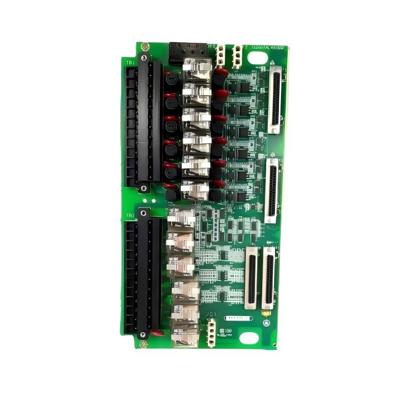
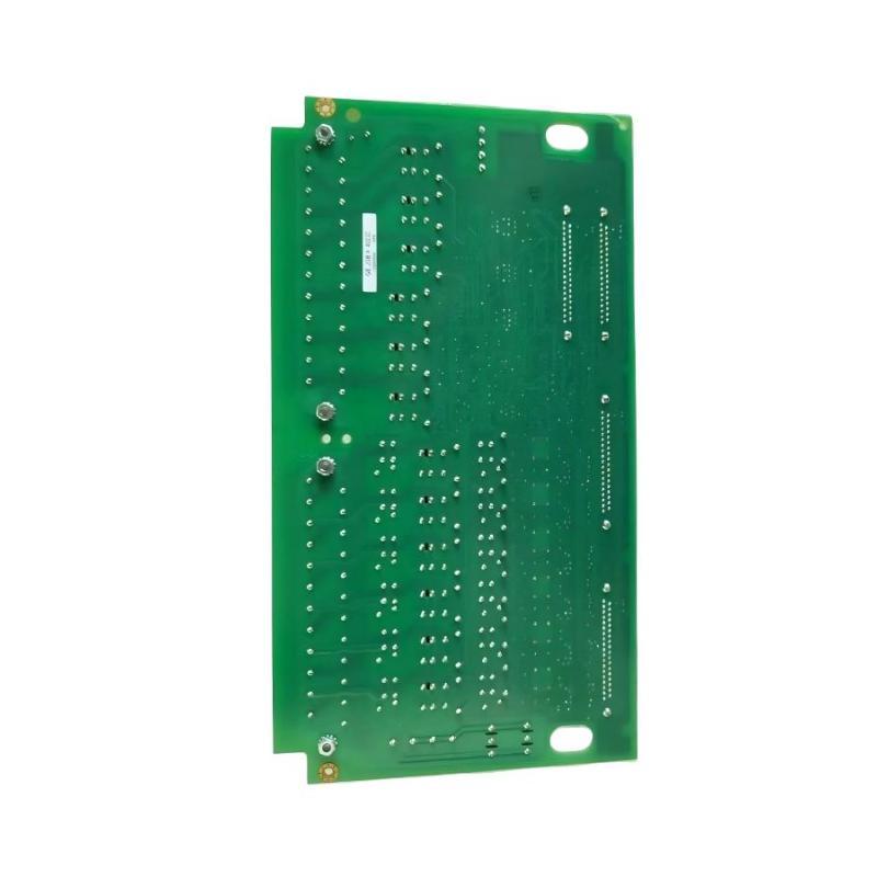
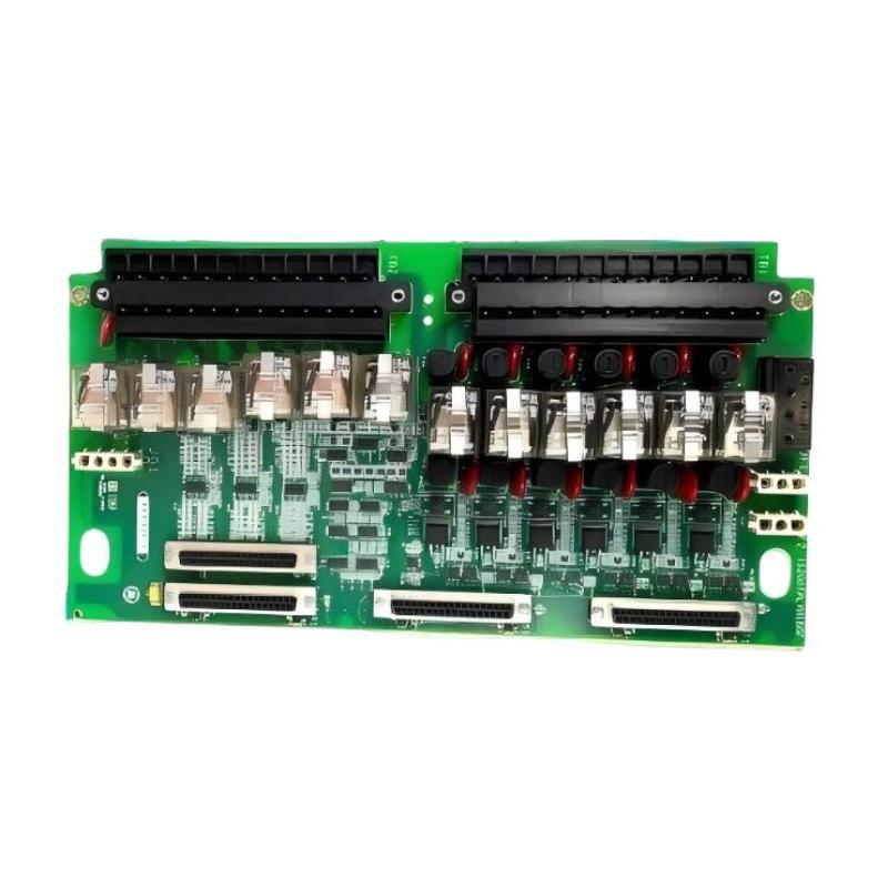
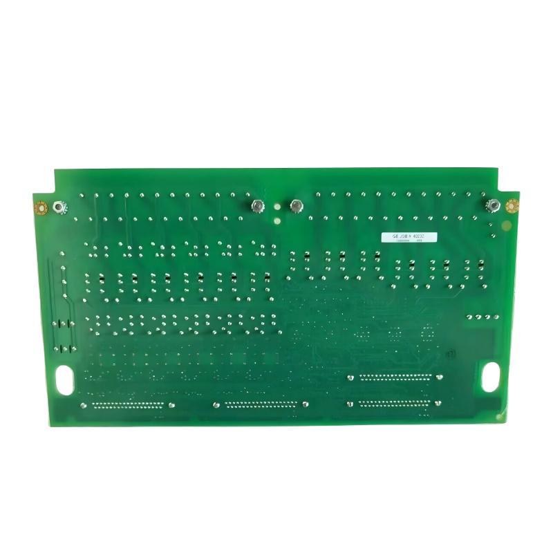
- GE
- IS239TRLYH1B
- Printed Circuit Board
- USA
- 200 × 120 × 35 mm
- 1.05 kg
- Xiamen, China
- New & In Stock
- T/T, PayPal, Western Union
- 1 Year
- 1-3 Working Days
- DHL, UPS, TNT, FedEx and EMS.
- 24-Hour Service
- COO
- 25
Our advantage

Global Logistics
We have a 10-year logistics and express cooperation agreement, so our products can be shipped to any place in the world.

Brand new and original
Our products are imported in bulk from the place of origin. Because of the cooperative relationship, our products are all original and 100% new.

24-hour service
We provide 7*24 hours service to our customers. We will be there whenever you need us.

Price advantage
All our products are priced very favorably because we have our own warehouse and supply.
| Company Information | |||
| [email protected] | |||
| Mobile | +8615980777398 | ||
| +8615980777398 | |||
| 15980777398 |
Product Overview
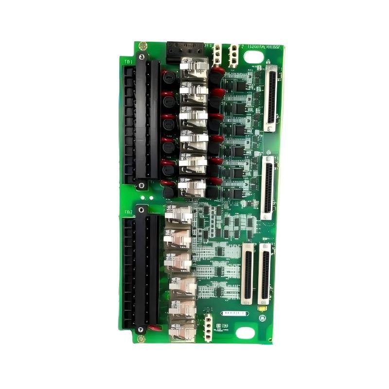
The GE IS239TRLYH1B Printed Circuit Board (PCB) is an industrial electronic assembly intended for use within a compatible control or automation system. Printed circuit boards provide the electrical interconnections and component mounting required for electronic signal handling, control functions, and communication between different parts of an industrial equipment architecture.
In industrial automation, specialized circuit boards help connect electronic components and support the operation of larger control assemblies. Their actual functions depend on the board design, installed components, connector arrangement, and host equipment. Correct identification is therefore essential when selecting a replacement or planning maintenance.
The GE IS239TRLYH1B is identified by its supplied model number as a printed circuit board. Its precise circuit function, supported interfaces, electrical ratings, and host-system compatibility should be confirmed against the relevant equipment documentation before installation. The model designation alone is not sufficient to establish the board’s exact signal-processing or control capabilities.
With dimensions of 200 × 120 × 35 mm and a weight of approximately 1.05 kg, the IS239TRLYH1B has a defined physical footprint for equipment layout, inventory management, and replacement planning. Maintaining the correct board identification helps reduce the risk of installing an incompatible assembly in an industrial control cabinet.
Whether used for replacement, maintenance, or spare-parts inventory, the GE IS239TRLYH1B should be evaluated according to its intended application, revision markings, connectors, and compatibility with the existing equipment.
Technical Specifications
| Parameter | Specification |
|---|---|
| Manufacturer | General Electric (GE) |
| Model | IS239TRLYH1B |
| Product Type | Printed Circuit Board (PCB) |
| Product Family | GE IS239 Series designation |
| Primary Function | Industrial electronic circuit assembly; specific function requires verification |
| Application | Industrial control and automation equipment |
| Circuit Configuration | Confirm from the applicable hardware documentation |
| Input/Output Interfaces | Verify according to the installed system |
| Communication Functions | Not confirmed; check the equipment specification |
| Operating Voltage | Verify from the applicable technical documentation |
| Electrical Ratings | Confirm before installation |
| Dimensions | 200 × 120 × 35 mm |
| Weight | 1.05 kg |
| Installation | Compatible industrial control equipment |
| Maintenance | Inspection of the PCB, connectors, mounting points, and associated wiring |
The specifications above preserve the supplied product identification and physical data. Detailed electrical parameters and functional characteristics should be verified before the board is commissioned.
What Is the GE IS239TRLYH1B Printed Circuit Board?
A printed circuit board is an electronic assembly that mechanically supports components and connects them through conductive pathways. Depending on its design, a PCB may perform signal conditioning, electrical interfacing, control logic, data communication, power distribution, or other specialized functions.
In industrial equipment, circuit boards are often designed for a specific system architecture. Their connectors, electrical characteristics, and installed components determine how they interact with other control hardware.
The GE IS239TRLYH1B should therefore be treated as a model-specific industrial electronic assembly rather than a generic replacement PCB. Its precise role must be established from the installed equipment, board markings, circuit documentation, and original parts identification.
A simplified industrial control arrangement can be represented as:
Field Devices → Interface Electronics → Control Circuit Board → System Control Hardware → Monitoring or Equipment Response
This diagram illustrates a general control architecture, not a verified internal signal path for the IS239TRLYH1B.
Function and Working Principle
The operation of a printed circuit board depends on its electronic design and the function it performs within the host system. Industrial PCBs may contain integrated circuits, resistors, capacitors, transistors, connectors, and other components arranged to perform a defined electrical task.
For the IS239TRLYH1B, the specific circuitry and functional role should be confirmed before assigning detailed operating characteristics.
Electronic Interconnection
Conductive tracks connect electronic components and establish the electrical paths needed for the board’s intended function. Connectors provide interfaces to other circuit boards, power sources, sensors, or external equipment, depending on the design.
Reliable interconnection is important because damaged tracks, poor solder joints, or contaminated connectors can interrupt electrical signals.
Signal Handling
Some industrial circuit boards receive electrical signals and prepare them for use by other system components. Depending on the design, this can involve filtering, switching, isolation, amplification, or other electronic operations.
These functions should not be attributed specifically to the IS239TRLYH1B without confirmation from its technical documentation.
Interaction With Other Control Hardware
A circuit board generally operates as part of a larger system rather than as an independent device. It may depend on a host assembly, external power, configured interfaces, and associated hardware to perform its intended function.
The correct combination of components is essential for reliable operation.
System-Level Operation
The overall performance of an industrial PCB depends on both the board and its operating environment. Power quality, temperature, vibration, grounding, connector integrity, and correct configuration can all influence system reliability.
Understanding the complete installation is therefore important when diagnosing a suspected board fault.
Role in Industrial Automation
Industrial automation systems combine multiple electronic assemblies to monitor equipment, process signals, execute control logic, and communicate operating information. Specialized PCBs provide the hardware foundation for many of these functions.
Depending on its verified application, the IS239TRLYH1B may form part of an industrial electronic assembly that interacts with other control equipment. Its role should be determined from the actual system architecture rather than inferred from the general PCB product category.
Common functions performed by industrial circuit boards include:
- Establishing electrical connections between electronic components.
- Supporting specialized control or interface functions.
- Providing connections to associated hardware.
- Participating in signal-handling or monitoring circuits.
- Supporting the operation of larger industrial equipment.
- Allowing modular replacement during maintenance.
These are general functions of industrial PCBs, not a confirmation that every function is implemented by the IS239TRLYH1B.
Industrial Applications
Industrial printed circuit boards are used across a broad range of automation and equipment-control environments. The suitability of the IS239TRLYH1B for a specific application depends on its confirmed function and compatibility with the host equipment.
Industrial Control Cabinets
Control cabinets contain electronic assemblies that work together to manage equipment operation, collect signals, and provide interfaces between different system elements. A model-specific PCB can be an important part of this arrangement.
Manufacturing Automation
Automated production lines use electronic control hardware to coordinate machinery, monitor conditions, and maintain repeatable operating sequences. Specialized circuit boards support the electronic functions required by these systems.
Power and Electrical Equipment
Industrial power equipment may contain circuit boards for control, measurement, monitoring, or interface functions. Replacement hardware must match the electrical and environmental requirements of the original installation.
Process Automation
Process industries rely on electronic equipment to support monitoring and control in applications such as water treatment, chemical processing, utilities, and manufacturing. Circuit boards can provide dedicated functions within these larger systems.
Equipment Maintenance and Repair
Printed circuit boards may require inspection or replacement when physical damage, electrical failure, contamination, or connector problems affect system operation. Correct identification helps maintenance teams select an appropriate replacement and avoid unnecessary changes to the equipment configuration.
These examples describe common industrial PCB applications and should not be interpreted as confirmation of specific end uses for the IS239TRLYH1B.
Installation and System Integration
Correct installation helps protect the circuit board and reduces the risk of electrical faults, connector damage, and system incompatibility. The IS239TRLYH1B should be installed only in equipment for which its identity and function have been verified.
1. Confirm the Board Identification
Check the complete model number IS239TRLYH1B and compare it with the original assembly, equipment parts list, and maintenance documentation.
Where available, record revision markings, serial information, connector locations, and other identification details. Do not assume that boards with similar dimensions or appearances are interchangeable.
2. Follow Electrical Safety Procedures
Before removing or installing the PCB, follow the site’s approved isolation and lockout/tagout procedures. Confirm that the equipment is in a safe condition and that applicable electrical hazards have been addressed.
Only qualified personnel should carry out work on industrial control electronics.
3. Observe Electrostatic Discharge Precautions
Electronic components can be damaged by electrostatic discharge even when no visible damage occurs. Use suitable ESD protection, including approved grounding equipment and handling procedures.
Hold the board by its edges where practical, and avoid touching exposed components, conductive tracks, or connector contacts unnecessarily.
4. Inspect the Installation Area
Before fitting the board, inspect the mounting area, connectors, adjacent hardware, and wiring. Look for contamination, corrosion, loose mounting points, damaged contacts, or evidence of overheating.
Correct any installation-related problems before fitting the replacement.
5. Verify Connectors and Wiring
Compare connector positions and keying features with the approved system documentation. Confirm that all associated cables and interfaces are intended for the board.
Never force a connector into place or alter wiring based on assumptions about pin assignments.
6. Secure the Assembly
Install the PCB according to the equipment’s specified mounting arrangement. Ensure that it is properly supported and that no cable, fastener, or nearby component places undue mechanical stress on the assembly.
Maintain the required clearance and environmental conditions for the host equipment.
7. Perform Commissioning Checks
After installation, follow the system’s prescribed startup and diagnostic procedures. Check for hardware alarms, abnormal indications, and unexpected operating behavior.
Where required, verify the associated circuit function using approved test procedures before returning the equipment to normal service.
Troubleshooting the GE IS239TRLYH1B
A suspected PCB failure should be investigated systematically. Symptoms attributed to a circuit board can also result from power-supply problems, connector faults, wiring damage, configuration errors, or failures in other system components.
Equipment Fails to Start or Operate
If the equipment does not operate after installation, check the following:
- Confirm that the correct board model and revision have been installed.
- Review the host system’s diagnostic messages.
- Verify the required power supply and associated electrical connections.
- Inspect connectors and mounting points.
- Check for incorrectly connected or damaged cables.
- Confirm that related control hardware is operating normally.
Do not conclude that the PCB is defective until other likely causes have been investigated.
Intermittent System Faults
Intermittent failures may result from loose connectors, cracked solder joints, damaged wiring, vibration, contamination, or temperature-related issues.
Review fault records and operating conditions to identify when the problem occurs. Inspect connections under safe conditions and use the approved diagnostic process to isolate the affected component.
Visible Damage or Overheating
Discoloration, burnt areas, damaged components, cracked circuit material, or unusual odor can indicate an electrical or environmental problem.
The equipment should be placed in a safe condition before inspection. Determine the cause of the damage, including possible overloads, incorrect wiring, poor connections, or environmental stress, before installing replacement hardware.
No Response From an Associated Interface
If connected equipment does not respond, inspect the complete interface path. This may include the host controller, relevant cables, connectors, power supply, configuration, and external equipment.
The exact troubleshooting steps depend on the verified function of the IS239TRLYH1B and the system in which it is installed.
Repeated Hardware Alarms
Repeated alarms may indicate an incompatible board, an incorrect installation, an unstable power source, a connection problem, or a failure elsewhere in the control system.
Record the exact alarm information and compare the installed hardware with the approved configuration. Avoid repeatedly resetting the system without identifying the underlying cause.
Maintenance Recommendations
Preventive maintenance can help preserve PCB reliability and reduce unexpected downtime.
Regular Visual Inspection
Inspect the board and surrounding assembly for dust accumulation, corrosion, damaged components, loose mounting, or signs of overheating. The inspection interval should reflect the operating environment and maintenance requirements of the equipment.
Connector Maintenance
Check connectors for contamination, damaged contacts, loose locking mechanisms, and signs of wear. Clean or service connections only using approved methods suitable for the installed hardware.
Environmental Control
Maintain appropriate temperature, humidity, cleanliness, and ventilation within the control cabinet. Excessive moisture, conductive dust, heat, and vibration can contribute to premature electronic failure.
Power Supply Verification
Where appropriate, verify that the associated power supply operates within the limits specified for the system. Electrical disturbances or incorrect supply conditions can cause faults that appear to originate from a circuit board.
ESD-Safe Handling
Use appropriate electrostatic discharge precautions whenever the PCB is removed, inspected, stored, or replaced. Store spare boards in suitable protective packaging until required.
Maintenance Records
Record the model number, revision information, installation date, reported symptoms, diagnostic results, and replacement details. Accurate records help identify recurring failures and simplify future maintenance.
Compatible System Components
The GE IS239TRLYH1B may operate within a larger control assembly containing other electronic and electrical components. The exact compatible part numbers cannot be established from the product name and physical specifications alone.
| Component Category | Typical Function |
|---|---|
| Host Control Assembly | Provides the equipment environment in which the PCB operates |
| Power Supply | Provides the required electrical power |
| Interface Hardware | Connects the PCB to associated system components |
| Control Processor | Executes control logic where required by the architecture |
| Input/Output Hardware | Transfers signals between the control system and external equipment |
| Wiring and Connectors | Establish electrical connections between assemblies |
| Operator Interface | Displays operating status and diagnostic information |
| Cabinet Grounding System | Supports the required grounding and electrical safety arrangement |
This table lists general component categories rather than verified compatible products. Confirm the required hardware and interfaces using the original equipment documentation before purchasing or installing related components.
Replacement and Procurement Considerations
Selecting a replacement for the GE IS239TRLYH1B Printed Circuit Board requires careful attention to identification and compatibility. An incorrect board can cause installation difficulties, electrical incompatibility, hardware alarms, or loss of the intended equipment function.
Before ordering, verify the following details:
- Complete model number: IS239TRLYH1B
- Revision or hardware identification markings.
- Original equipment and installation location.
- Connector arrangement and interface configuration.
- Required electrical characteristics.
- Approved replacement status.
- Physical dimensions and mounting requirements.
- Condition of associated cables and system hardware.
The supplied dimensions are 200 × 120 × 35 mm, and the listed weight is 1.05 kg. These measurements can support spare-parts planning, shipping preparation, and cabinet-layout assessment.
If a supplier offers an alternative model, request confirmation of functional and electrical interchangeability. A similar model number, product family, or physical appearance is not sufficient proof of compatibility.
Key Advantages
Defined Physical Specifications
The supplied dimensions and weight provide useful information for inventory management, equipment handling, and replacement planning.
Modular Maintenance Approach
Where the host system supports board-level replacement, a correctly identified PCB can help maintenance personnel address a localized hardware problem without unnecessarily replacing an entire assembly.
Integration With Industrial Electronics
Printed circuit boards provide the electrical interconnections required for specialized industrial control and interface functions.
Support for System Reliability
Correct installation, proper environmental control, and systematic troubleshooting help maintain reliable operation of the electronic assembly.
Improved Maintenance Traceability
Accurate board identification and maintenance records help technicians track replacements, investigate recurring faults, and maintain the integrity of the installed hardware configuration.
Technical FAQs
What is the GE IS239TRLYH1B?
The GE IS239TRLYH1B is identified as an industrial Printed Circuit Board (PCB). Its precise function should be confirmed from the applicable equipment documentation and original hardware identification.
What are the dimensions of the IS239TRLYH1B?
The supplied dimensions are 200 × 120 × 35 mm.
How much does the IS239TRLYH1B weigh?
The supplied weight is approximately 1.05 kg.
What does a printed circuit board do in an industrial control system?
A PCB supports electronic components and connects them through conductive pathways. Depending on its design, it may provide control, signal handling, communication, power distribution, or interface functions.
Can any GE circuit board with similar dimensions replace the IS239TRLYH1B?
No. Physical dimensions alone do not establish compatibility. The complete model number, revision, electrical characteristics, connectors, and host-system requirements must be checked.
What should be checked before installing the board?
Verify the board identity, host-system compatibility, connector arrangement, required power conditions, mounting requirements, and applicable safety procedures. Use ESD protection when handling the electronic assembly.
What can cause PCB-related system faults?
Potential causes include electronic component failure, damaged circuit tracks, poor solder connections, contaminated connectors, unstable power, incorrect installation, environmental stress, or problems elsewhere in the system.
How should the IS239TRLYH1B be stored?
Store the board in suitable protective packaging that limits electrostatic discharge, moisture exposure, contamination, and mechanical damage. Follow the storage requirements for the specific electronic assembly.
Conclusion
The GE IS239TRLYH1B Printed Circuit Board is an industrial electronic assembly identified for use within a compatible control or automation environment. As with other specialized industrial PCBs, its successful operation depends on correct hardware identification, suitable electrical interfaces, proper installation, and compliance with the host equipment’s requirements.
With supplied dimensions of 200 × 120 × 35 mm and a weight of 1.05 kg, the board can be identified for inventory management, equipment planning, and replacement preparation. Its specific circuit function and compatibility should be verified before installation rather than inferred from the product category alone.
For maintenance and procurement, confirm the complete IS239TRLYH1B designation, check all relevant revision and connector details, use electrostatic discharge precautions, and perform the required commissioning checks. These practices help reduce replacement errors and support the dependable operation of industrial electronic control equipment.