

ProductPRODUCT
Featured products



Contact Us
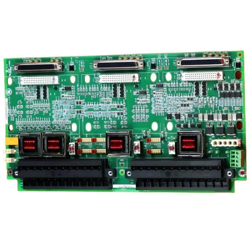
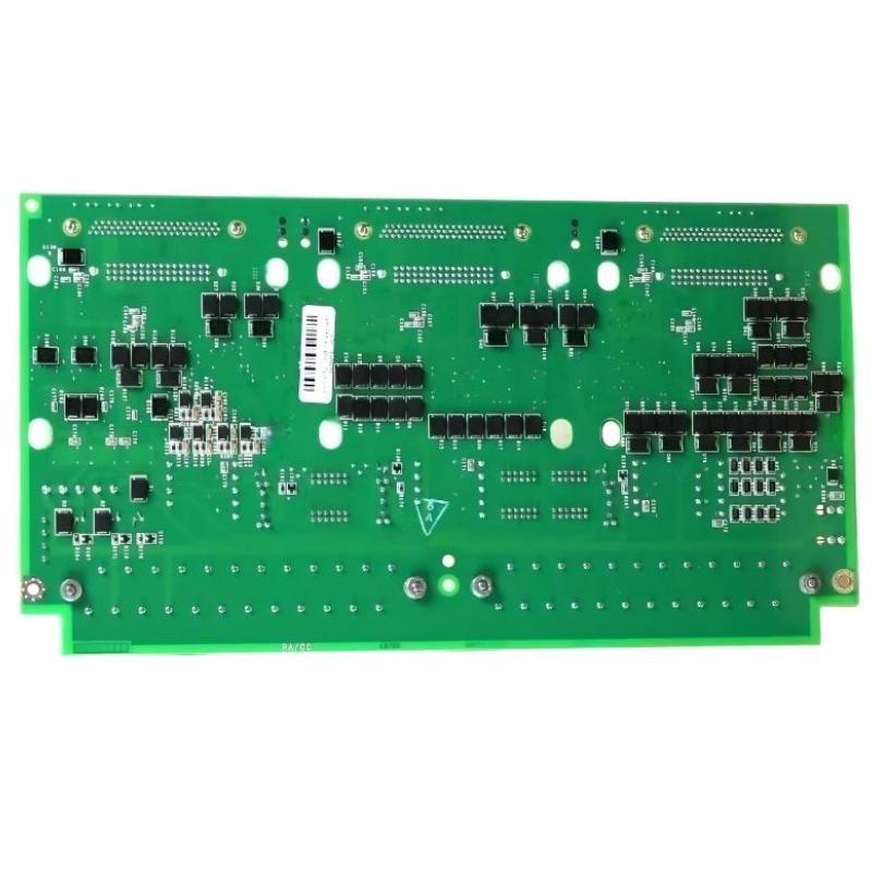
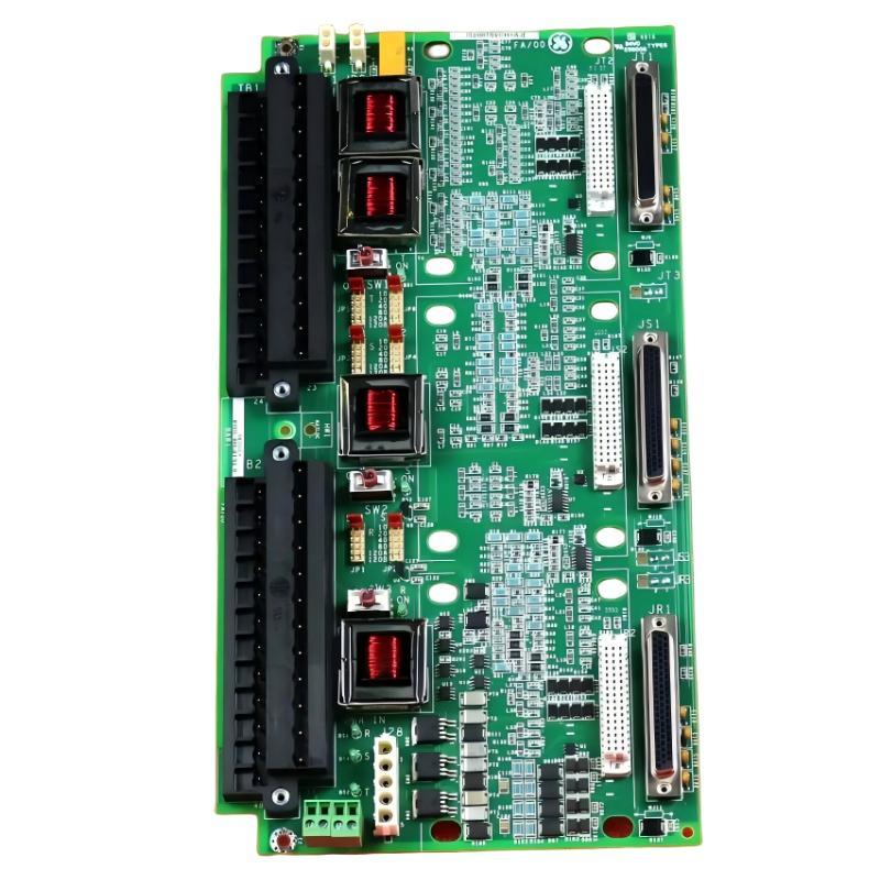
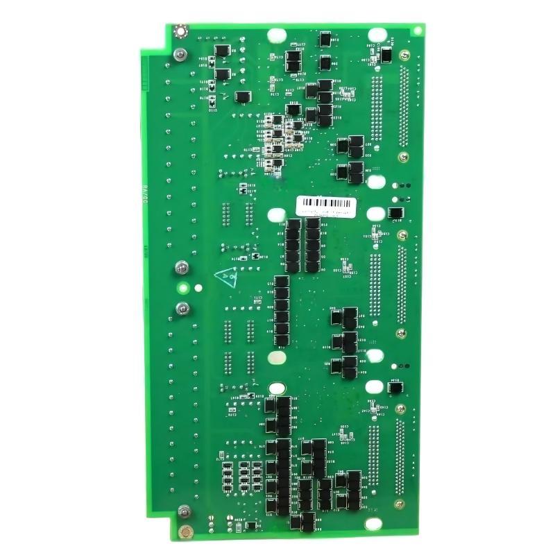
- GE
- IS230TNSVH3A IS200TSVCH1AJE
- Servo Terminal Block
- USA
- 225 x 167 x 55 mm
- 0.5 kg
- Xiamen, China
- New & In Stock
- T/T, PayPal, Western Union
- 1 Year
- 1-3 Working Days
- DHL, UPS, TNT, FedEx and EMS.
- 24-Hour Service
- COO
- 26
Our advantage

Global Logistics
We have a 10-year logistics and express cooperation agreement, so our products can be shipped to any place in the world.

Brand new and original
Our products are imported in bulk from the place of origin. Because of the cooperative relationship, our products are all original and 100% new.

24-hour service
We provide 7*24 hours service to our customers. We will be there whenever you need us.

Price advantage
All our products are priced very favorably because we have our own warehouse and supply.
| Company Information | |||
| [email protected] | |||
| Mobile | +8615980777398 | ||
| +8615980777398 | |||
| 15980777398 |
Product Overview
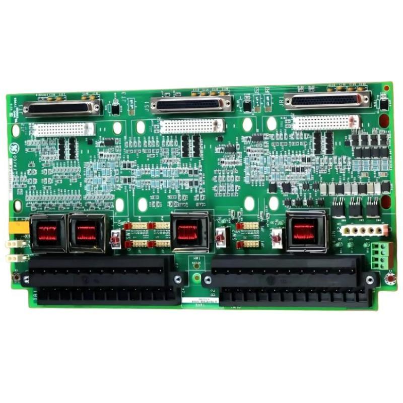
The GE IS230TNSVH3A / IS200TSVCH1AJE Servo Terminal Block is an industrial control component intended for use within compatible GE automation and control equipment. Terminal blocks provide organized electrical connection points that help connect control hardware with associated wiring and external devices. In servo-related applications, terminal hardware can form part of the electrical interface between control electronics and the equipment responsible for motion or actuator operation.
Industrial servo systems require dependable electrical connections to support command transmission, status monitoring, and coordinated equipment operation. A correctly identified terminal block helps maintain an organized wiring arrangement, simplifies maintenance, and reduces the risk of connection errors during equipment servicing. Its exact function depends on the hardware configuration and the host system in which it is installed.
The GE IS230TNSVH3A and IS200TSVCH1AJE identifiers should be verified against the installed component, equipment records, and applicable parts documentation before replacement. Similar-looking terminal assemblies may have different connector assignments, electrical functions, or system compatibility. The complete part number and revision should therefore be checked rather than relying on appearance alone.
With listed dimensions of 225 × 167 × 55 mm and a weight of approximately 0.5 kg, this servo terminal block is suitable for maintenance planning, cabinet-space assessment, and spare-parts management in industrial automation environments.
Technical Specifications
| Parameter | Specification |
|---|---|
| Manufacturer | General Electric (GE) |
| Model Number | IS230TNSVH3A |
| Associated Part Number | IS200TSVCH1AJE |
| Product Type | Servo Terminal Block |
| Product Family | GE IS200 / IS230 Industrial Control Hardware |
| Primary Function | Electrical termination and interface within a compatible control system |
| Application Area | Servo-related industrial control and automation |
| Dimensions | 225 × 167 × 55 mm |
| Weight | 0.5 kg |
| Installation | Compatible equipment mounting arrangement |
| System Compatibility | Must be confirmed against the host equipment and hardware revision |
| Maintenance Requirement | Periodic inspection of mounting, terminals, and associated wiring |
Note: Terminal assignments, voltage and current ratings, connector types, supported servo equipment, and exact host-system compatibility must be confirmed using the component markings and the applicable equipment documentation.
What Is a Servo Terminal Block?
A servo terminal block is an electrical connection component used to organize and terminate conductors associated with a servo or motion-control installation. Depending on the design, terminal hardware may provide connection points for control signals, status signals, power-related wiring, or other designated interfaces.
The term “servo terminal block” describes the product category, but it does not by itself establish the exact electrical function of a specific GE assembly. The role of the IS230TNSVH3A / IS200TSVCH1AJE must be determined from its approved installation configuration.
In a typical industrial control arrangement, a terminal assembly may help connect control electronics with field wiring and associated equipment. Correct termination is important because loose, damaged, or incorrectly positioned conductors can interrupt signals and cause unexpected system behavior.
The principal maintenance objectives for terminal hardware include:
- Maintaining secure and correctly positioned electrical connections.
- Keeping wiring organized and identifiable.
- Supporting efficient inspection and fault isolation.
- Reducing the likelihood of wiring mistakes during replacement.
- Preserving the intended electrical interface of the original system.
- Simplifying maintenance documentation and spare-part identification.
Function and Working Principle
Electrical Connection Management
Terminal blocks provide designated connection points for conductors. In a servo-related installation, these connections may form part of the interface between the control system and associated motion equipment. The exact signals and connections depend on the specific assembly.
Signal Interconnection
Servo systems rely on coordinated communication between control electronics and the devices they manage. Depending on the system design, terminal hardware may support the routing of designated command, status, or interface signals.
The actual signal types and terminal assignments for the IS230TNSVH3A / IS200TSVCH1AJE should be confirmed before wiring or commissioning.
Wiring Organization
A well-arranged terminal interface helps technicians identify individual conductors and trace connections during troubleshooting. Clear labeling and correct wire routing can reduce maintenance time and lower the risk of accidental cross-connections.
Support for System Maintenance
When terminal hardware is damaged or connections become unreliable, a verified replacement can help restore the intended installation. However, replacing the terminal block will not resolve faults originating in the servo controller, motor, feedback device, power supply, or external wiring.
Role in Industrial Servo Control Systems
Industrial servo systems are used when equipment requires controlled motion, repeatable positioning, or coordinated movement. Depending on the application, a complete system may include a controller, servo drive, motor, feedback device, electrical interfaces, and associated mechanical equipment.
A simplified system arrangement is:
Motion Controller → Servo Drive and Control Interfaces → Servo Motor → Mechanical Load
Feedback and status information may travel through separate paths defined by the system architecture. A terminal block can provide part of the required electrical connection structure, but its exact position in this arrangement must be established from the equipment documentation.
In a properly configured system, secure electrical connections help maintain signal continuity and reliable equipment operation. Incorrect terminal assignments or poor connections may lead to communication errors, drive faults, intermittent operation, or failure to execute a motion command.
The IS230TNSVH3A / IS200TSVCH1AJE should therefore be installed only in its designated position within the compatible GE control assembly.
Industrial Applications
Servo and Motion-Control Equipment
Servo-based machinery depends on coordinated electrical connections between control devices and motion hardware. A suitable terminal block can help maintain the wiring arrangement specified for the equipment.
Automated Manufacturing
Manufacturing lines often combine motion control with sensors, actuators, conveyors, and supervisory control equipment. Reliable terminal connections help support maintenance and troubleshooting within these interconnected systems.
Packaging Machinery
Packaging equipment may use servo-driven mechanisms for indexing, positioning, cutting, feeding, and other repetitive movements. Correctly maintained electrical interfaces help reduce the risk of connection-related interruptions.
Material Handling Systems
Automated handling equipment can incorporate servo-driven positioning mechanisms and other controlled devices. Properly identified terminal hardware helps technicians maintain the electrical installation during planned service.
Industrial Equipment Refurbishment
When older control equipment is refurbished, terminal blocks and associated wiring should be inspected for physical damage, corrosion, loose connections, and signs of overheating. Replacements should match the original hardware requirements.
These examples describe general servo and industrial automation applications. The suitability of this particular GE component must be confirmed for the intended machine or control system.
Installation and System Integration
Correct installation is essential for electrical safety, signal integrity, and long-term serviceability. Installation should be carried out by qualified personnel following the procedures applicable to the host equipment.
1. Confirm the Part Number
Before removing an existing component, record its complete identification. Verify:
- IS230TNSVH3A model designation.
- IS200TSVCH1AJE associated part number.
- Revision or suffix information.
- Terminal and connector arrangement.
- Mounting configuration.
- Existing installation position.
- Associated servo and control hardware.
Do not assume that another terminal block is interchangeable simply because its dimensions are similar.
2. Isolate the Equipment
Follow the site’s approved shutdown and lockout/tagout procedures before opening the control cabinet or disconnecting wiring. Verify that all relevant power sources have been isolated and that hazardous voltage is absent.
Servo drives and related equipment may contain stored electrical energy after power is removed. Follow the manufacturer’s discharge and waiting-time instructions before handling terminals or connectors.
3. Document the Existing Wiring
Before disconnecting conductors, record the existing wiring arrangement using approved diagrams, labels, and maintenance records. Ensure that each conductor can be returned to its designated terminal.
Photographs may help document the physical arrangement, but they should supplement rather than replace the approved wiring diagram.
4. Inspect the Mounting Location
Check the mounting area for damage, contamination, loose hardware, restricted access, and interference from neighboring components. The replacement should be installed securely using the specified mounting method.
The listed dimensions are 225 × 167 × 55 mm. Confirm that the available space and wiring clearances are appropriate for the actual installation.
5. Reconnect the Wiring
Reconnect conductors according to the approved terminal assignments. Check wire identification, connector engagement, conductor condition, and any specified termination requirements.
Do not infer terminal functions from the position of adjacent terminals or from another model’s wiring diagram.
6. Perform Pre-Commissioning Checks
Before restoring the equipment to operation, verify:
- Correct component identification.
- Secure mechanical mounting.
- Correct conductor placement.
- Proper connector engagement.
- No loose wires or foreign objects.
- No visible damage to the terminal assembly.
- Completion of all required electrical safety checks.
Follow the host system’s commissioning procedure before returning the equipment to service.
Troubleshooting and Fault Diagnosis
Terminal-related problems may cause symptoms that resemble failures in the servo drive or controller. A systematic inspection can help identify whether the fault originates in the terminal block, the associated wiring, or another part of the system.
Servo Equipment Fails to Respond
Possible causes:
- Loose or disconnected control wiring.
- Incorrectly restored terminal connections.
- Damaged conductors.
- Incorrect replacement hardware.
- A fault in the controller, drive, or associated equipment.
Recommended checks:
- Review the system’s fault and diagnostic information.
- Verify the installed part number and revision.
- Inspect the wiring against the approved diagram.
- Check connectors and terminals after isolating the equipment.
- Investigate the controller and drive if the terminal connections are correct.
Intermittent Servo Operation
Intermittent operation may be associated with loose connections, damaged conductors, vibration, contamination, or faults in connected equipment.
Inspect the terminal assembly and wiring under the approved maintenance procedure. Check for cable strain and ensure that conductors are correctly retained. Do not reseat or manipulate energized connections unless explicitly permitted by the equipment documentation.
Communication or Signal Errors
Signal errors can result from incorrect wiring, damaged cables, poor connections, electrical interference, or faults in the connected control hardware.
Confirm the designated signal path and wiring requirements before making changes. The terminal block should not be assumed to be the cause until the connected equipment and wiring have been checked.
Visible Terminal Damage
Discoloration, corrosion, cracked insulation, melted material, or burn marks may indicate overheating, contamination, or an electrical problem.
Do not return visibly damaged hardware to service without determining the cause. Inspect the associated wiring and connected equipment, and replace the affected component according to the approved maintenance procedure.
Fault Persists After Replacement
If the original symptom remains after installation of a verified replacement, investigate other possible causes, including the servo drive, controller, power supply, feedback device, field wiring, and mechanical load.
Replacing terminal hardware alone cannot correct a fault elsewhere in the control system.
Maintenance Recommendations
A preventive maintenance program helps maintain terminal connection integrity and reduces the risk of avoidable equipment interruptions.
Periodic Visual Inspection
Inspect the assembly for cracks, contamination, corrosion, discoloration, and other visible damage. The inspection interval should reflect the operating environment and the site’s maintenance requirements.
Connection Integrity
Check connections according to the approved maintenance procedure. Where specified, use the correct tools and tightening requirements. Avoid arbitrary retightening because excessive force can damage terminals or conductors.
Wiring Condition
Inspect accessible wiring for damaged insulation, loose retention, abrasion, and excessive strain. Verify that cable routing remains consistent with the installation design.
Environmental Management
Keep the control cabinet within the environmental limits specified for the installed equipment. Excessive dust, moisture, corrosive substances, and vibration can degrade connections and surrounding components.
Maintenance Records
Record the installed part number, revision, inspection findings, and replacement history. Accurate records help technicians identify the correct component during future maintenance.
Spare-Part Storage
Store replacement terminal hardware in a clean, dry environment with suitable protection against electrostatic discharge where applicable. Keep the product identification label intact so the part can be verified before use.
Compatible System Components
The IS230TNSVH3A / IS200TSVCH1AJE may form part of a larger control installation containing several functional groups of equipment.
| Component Category | General Function |
|---|---|
| Servo Controller | Generates or coordinates motion commands |
| Servo Drive | Controls the operation of a compatible servo motor |
| Servo Motor | Produces controlled mechanical movement |
| Feedback Device | Provides position, speed, or other feedback where supported |
| Terminal Block | Provides designated electrical connection points |
| Control Wiring | Carries specified command and status signals |
| Power Distribution Equipment | Supplies electrical power to compatible devices |
| Industrial Controller | Coordinates machine or process logic |
| Operator Interface | Displays machine status and diagnostic information |
This is a general system-level overview, not a confirmed compatibility list for the specific terminal block. Exact compatible controllers, drives, motors, and interface assemblies must be verified against the original equipment documentation.
Recommended Replacement Considerations
When sourcing the GE IS230TNSVH3A / IS200TSVCH1AJE Servo Terminal Block, procurement should focus on exact identification and application compatibility.
| Verification Item | Why It Matters |
|---|---|
| Complete Model Number | Helps distinguish the required assembly from similar products |
| Associated Part Number | Supports identification of the intended hardware |
| Revision or Suffix | May indicate differences in hardware configuration |
| Terminal Arrangement | Helps prevent incorrect wiring |
| Mounting Configuration | Ensures the component fits the designated installation |
| Host Equipment | Establishes the intended system application |
| Physical Condition | Helps identify damage or unsuitable storage conditions |
| Testing and Warranty Information | Supports procurement and maintenance planning |
The listed dimensions are 225 × 167 × 55 mm, and the weight is 0.5 kg. These measurements are useful for inventory and installation planning but do not establish electrical compatibility.
A replacement should not be selected solely by matching dimensions, product-family naming, or visual appearance. The complete part number and approved application should be confirmed before installation.
Key Advantages
Organized Electrical Connections
A suitable terminal block provides a structured connection arrangement for the wiring specified by the equipment design.
Easier Maintenance and Inspection
Clearly identified terminal hardware helps technicians trace connections and inspect wiring during scheduled maintenance.
Support for Reliable Servo-System Integration
When correctly matched to the host equipment, the terminal assembly helps maintain the intended electrical interface within a servo-related control installation.
Practical Replacement Planning
The model identification, dimensions, and weight support spare-parts records, storage planning, and replacement logistics.
Improved Troubleshooting Workflow
A clearly documented terminal arrangement can help maintenance personnel distinguish connection problems from faults in the controller, drive, motor, or other equipment.
Technical FAQs
What is the GE IS230TNSVH3A / IS200TSVCH1AJE?
It is identified in this product listing as a GE Servo Terminal Block associated with industrial control hardware. Its exact electrical role should be verified using the actual unit markings and host-system documentation.
What are the dimensions of this servo terminal block?
The listed dimensions are 225 × 167 × 55 mm.
How much does the module weigh?
The listed weight is approximately 0.5 kg.
What can cause servo faults related to terminal connections?
Potential causes include loose wiring, damaged conductors, incorrect terminal assignments, connector problems, contamination, or faults in connected control equipment.
Can another GE terminal block replace this model?
Not automatically. The complete part number, revision, terminal arrangement, and host-system requirements must be checked before using another model as a replacement.
Does this terminal block directly control a servo motor?
A terminal block generally provides electrical connection points rather than independently executing motion-control logic. The exact role of this particular assembly should be established from its designated system configuration.
What should be checked before commissioning?
Confirm the component identity, wiring arrangement, mounting security, connector engagement, and completion of required electrical safety checks. Follow the commissioning procedures specified for the host equipment.
How can the service life of the terminal block be supported?
Regular inspection, correct wiring practices, suitable environmental conditions, secure mounting, and accurate maintenance records can help preserve the condition of the assembly.
Conclusion
The GE IS230TNSVH3A / IS200TSVCH1AJE Servo Terminal Block is an industrial control component identified for servo-related electrical connection applications. With listed dimensions of 225 × 167 × 55 mm and a weight of approximately 0.5 kg, it can be included in equipment identification, cabinet planning, and spare-parts management activities.
Reliable operation depends on correct component identification, proper wiring, secure mounting, and compatibility with the intended GE control installation. Terminal assignments and electrical ratings should be verified before installation rather than inferred from the product name or physical dimensions.
For maintenance and replacement projects, confirming the full part number, revision, terminal configuration, and host equipment is essential. Combined with systematic troubleshooting and preventive inspection, these practices help support dependable electrical connections and maintainable industrial servo-control systems.