

ProductPRODUCT
Featured products



Contact Us
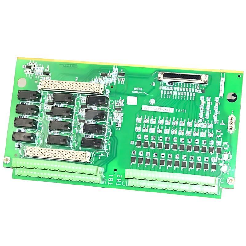
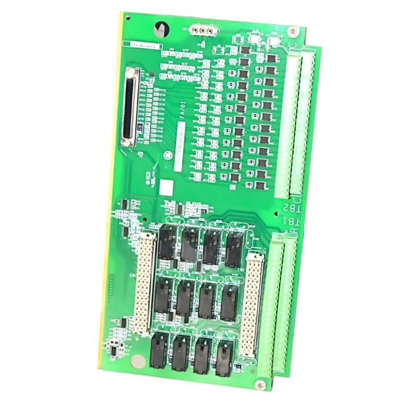
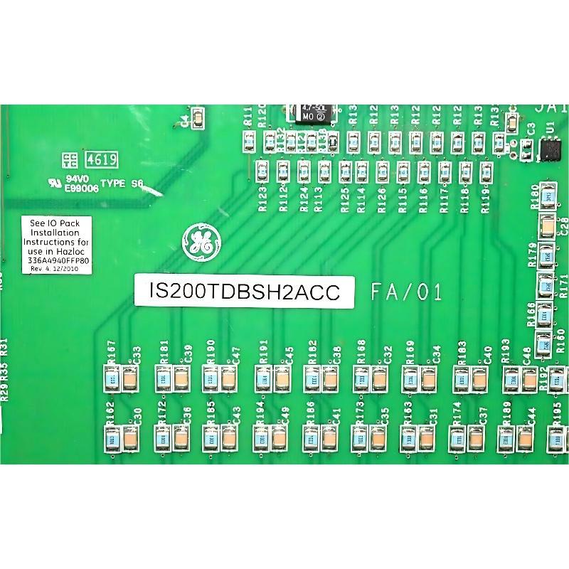
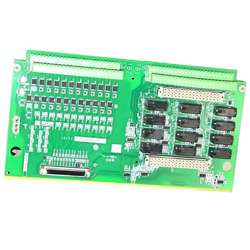
- GE
- IS230TNDSH2A IS200TDBSH2ACC
- DIN Rail Module
- USA
- 233 × 180 × 64mm
- 1.2 kg
- Xiamen, China
- New & In Stock
- T/T, PayPal, Western Union
- 1 Year
- 1-3 Working Days
- DHL, UPS, TNT, FedEx and EMS.
- 24-Hour Service
- COO
- 19
Our advantage

Global Logistics
We have a 10-year logistics and express cooperation agreement, so our products can be shipped to any place in the world.

Brand new and original
Our products are imported in bulk from the place of origin. Because of the cooperative relationship, our products are all original and 100% new.

24-hour service
We provide 7*24 hours service to our customers. We will be there whenever you need us.

Price advantage
All our products are priced very favorably because we have our own warehouse and supply.
| Company Information | |||
| [email protected] | |||
| Mobile | +8615980777398 | ||
| +8615980777398 | |||
| 15980777398 |
Product Overview
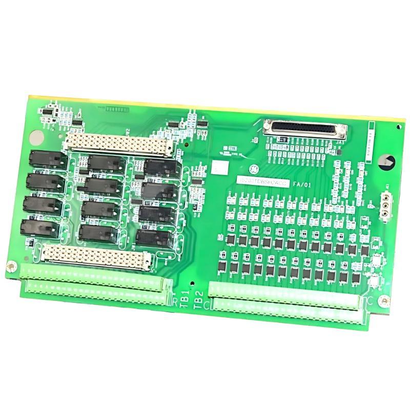
The GE IS230TNDSH2A / IS200TDBSH2ACC DIN Rail Module is an industrial control hardware component associated with GE automation and control equipment. Designed for integration into compatible industrial control assemblies, this module supports organized hardware installation and electrical interconnection within a larger control architecture. Its role in an industrial system depends on the exact board configuration, terminal arrangement, and host equipment in which it is installed.
DIN rail-based hardware is widely used in industrial automation because it provides a standardized method for mounting electrical and electronic components inside control cabinets. A well-organized mounting arrangement helps simplify wiring, supports maintenance activities, and improves access to individual components during inspection or replacement. In applications involving GE industrial control systems, correct module identification and installation are important for maintaining system integrity and reliable operation.
The GE IS230TNDSH2A and IS200TDBSH2ACC designations should be checked against the markings on the installed hardware and the relevant system documentation before procurement or replacement. Although the two identifiers are associated with the product supplied for this application, their interchangeability should not be assumed without confirmation of the applicable hardware revision and installation requirements.
With listed dimensions of 233 × 180 × 64 mm and a weight of approximately 1.2 kg, this module is intended for installation planning in industrial control cabinets and equipment assemblies where mounting space, wiring access, and component compatibility must be considered.
Technical Specifications
| Parameter | Specification |
|---|---|
| Manufacturer | General Electric (GE) |
| Model Number | IS230TNDSH2A |
| Associated Part Number | IS200TDBSH2ACC |
| Product Type | DIN Rail Module |
| Product Family | GE IS200 / IS230 Industrial Control Hardware |
| Primary Role | Industrial control hardware integration |
| Mounting Arrangement | DIN rail or compatible equipment mounting, subject to the hardware design |
| Dimensions | 233 × 180 × 64 mm |
| Weight | 1.2 kg |
| Installation Environment | Industrial control cabinet or compatible equipment enclosure |
| Application | Industrial automation and control-system integration |
| Replacement Requirement | Verify full part number, revision, connectors, and host-system compatibility |
Note: Electrical ratings, terminal assignments, I/O channel details, and exact host-system compatibility should be confirmed from the module nameplate and the applicable GE equipment documentation. They should not be inferred from the part number or physical dimensions alone.
Product Design and Functional Role
Industrial control systems combine processors, interface hardware, terminal assemblies, power distribution, communication components, and field wiring to monitor and control industrial processes. Each component must be installed in the correct position and connected according to the system’s electrical design.
The GE IS230TNDSH2A / IS200TDBSH2ACC is identified as a DIN rail module. DIN rail mounting provides a structured way to secure compatible components within an enclosure and helps maintain a consistent arrangement of control hardware.
Depending on the specific assembly, a module of this type may contribute to equipment organization, electrical interconnection, or the installation of control-related hardware. The precise function of this particular unit must be established from its complete part identification and the equipment in which it is used.
Correct installation supports several important maintenance and operational objectives:
- Maintaining the intended physical arrangement of control hardware.
- Preserving access to wiring and adjacent components.
- Reducing the risk of incorrect replacement or installation.
- Supporting systematic troubleshooting and inspection.
- Helping technicians identify and service individual assemblies.
- Maintaining compatibility with the original control-system configuration.
The module should therefore be treated as a designated component within a specific hardware arrangement rather than as a universally interchangeable DIN rail accessory.
Role in GE Industrial Control Systems
GE industrial control installations may include multiple layers of control and interface hardware. These layers work together to acquire process information, execute control logic, communicate status, and coordinate equipment operation.
A typical industrial control architecture can include:
- Control processor: Executes the configured control logic.
- Interface and terminal hardware: Provides the required connections between system components and field wiring.
- Power distribution: Supplies electrical power to compatible equipment.
- Communication hardware: Transfers control and status information where supported by the system.
- Field devices: Include sensors, switches, actuators, and other equipment connected to the process.
- Operator interface: Allows authorized personnel to observe system status, alarms, and operating conditions.
The IS230TNDSH2A / IS200TDBSH2ACC should be installed only in the position and configuration specified for the intended GE system. Its exact place in this architecture must be confirmed before electrical connections are made.
An incorrectly identified module may have a similar appearance to another assembly while using different electrical connections or serving a different function. Part-number verification is therefore essential when maintaining older or complex industrial control installations.
Industrial Applications
Industrial Automation Cabinets
Industrial control cabinets contain a range of electronic assemblies, wiring interfaces, protection devices, and mounting hardware. A correctly identified DIN rail module can be incorporated into the designated cabinet arrangement to support an organized and maintainable installation.
Power Generation and Plant Control
Power generation facilities use industrial control hardware to support monitoring, protection, and equipment coordination. When this module is specified for a compatible GE installation, maintaining its original configuration helps preserve the intended hardware arrangement.
Process Automation
Chemical processing, water treatment, manufacturing, and utility facilities often depend on structured control cabinets containing numerous interconnected components. Correctly mounted hardware helps technicians inspect connections and maintain equipment during planned service activities.
Industrial Equipment Maintenance
Replacement modules are important when an installed component becomes damaged, mechanically unstable, or otherwise unsuitable for continued use. Accurate identification allows maintenance teams to compare the replacement with the original assembly before installation.
Control-System Refurbishment
During cabinet refurbishment or equipment restoration, the mounting arrangement, wiring layout, and component identification should be documented before hardware is removed. This reduces the risk of installing a component in the wrong position or disturbing adjacent equipment.
These are general industrial control applications. The actual suitability of the IS230TNDSH2A / IS200TDBSH2ACC for any particular installation must be established from the original equipment configuration.
Installation and System Integration
Correct installation is important for mechanical stability, electrical safety, and long-term serviceability. The module should be handled and installed by qualified personnel following the procedures applicable to the host equipment.
1. Verify the Complete Part Number
Before installation, compare the existing component with the replacement. Check:
- Complete model and part number.
- Hardware revision or suffix.
- Manufacturer markings and labels.
- Connector and terminal arrangement.
- Mounting features and physical dimensions.
- Existing installation position.
- Associated hardware and host-system requirements.
The identifiers IS230TNDSH2A and IS200TDBSH2ACC should be confirmed against the installed assembly and system documentation. Do not assume that a shared product family or similar appearance establishes electrical compatibility.
2. Isolate the Equipment
Before working inside a control cabinet, follow the facility’s approved shutdown and lockout/tagout procedures. Isolate all relevant power sources and verify the absence of hazardous voltage using an appropriate method.
Stored energy may remain in certain industrial systems after the main supply is disconnected. Follow the manufacturer’s safety instructions before touching terminals, connectors, or internal components.
3. Inspect the Mounting Area
Examine the intended mounting location for:
- Damage to the DIN rail or mounting surface.
- Loose fasteners or retaining hardware.
- Dust, moisture, oil, or other contamination.
- Interference from adjacent components.
- Restricted wiring access.
- Signs of overheating or corrosion.
The mounting arrangement must support the module securely and provide adequate clearance for adjacent equipment and cable routing.
4. Install the Module
Use the mounting method specified for the actual hardware. Confirm that the component is seated securely and that any required retaining clips, brackets, or fasteners are correctly engaged.
Do not force the module into place. Mechanical resistance may indicate an incorrect mounting position, an incompatible rail arrangement, or interference with adjacent equipment.
5. Check Wiring and Connections
If the module uses electrical connectors or associated wiring, document the existing configuration before disconnecting anything. Label conductors where necessary and verify that each connection is restored to its designated position.
Never determine terminal assignments from physical appearance alone. Use the approved wiring diagram and equipment documentation.
6. Verify the Completed Installation
Before returning the equipment to service, inspect the installation for:
- Secure mechanical mounting.
- Correct connector engagement.
- Proper wire routing and retention.
- Adequate clearance around adjacent components.
- Absence of loose hardware or foreign objects.
- Correct part identification and revision.
Follow the host equipment’s commissioning procedure before restoring normal operation.
Troubleshooting and Fault Diagnosis
Problems involving a DIN rail-mounted component may arise from mechanical installation, incorrect identification, damaged connectors, wiring errors, or faults elsewhere in the control system. A structured inspection helps distinguish these possibilities.
Module Is Loose or Does Not Seat Correctly
Possible causes:
- Damaged DIN rail or mounting hardware.
- Incorrect mounting orientation.
- Missing or damaged retaining features.
- Interference from neighboring components.
- Incorrect replacement part.
Recommended checks:
- Isolate the equipment before inspection.
- Compare the mounting features with the original component.
- Inspect the rail, brackets, and retaining mechanism.
- Confirm the replacement’s complete part number.
- Replace damaged mounting hardware as specified by the equipment design.
System Fault Appears After Replacement
Possible causes:
- Incorrect part or revision.
- Connector not fully engaged.
- Wiring restored to the wrong position.
- A disturbed adjacent connection.
- An unrelated system fault that occurred during maintenance.
Recommended checks:
- Review the system’s diagnostic messages.
- Compare the installed hardware with the recorded configuration.
- Inspect connectors and wiring with the equipment safely isolated.
- Verify the replacement against the approved parts list.
- Follow the host system’s prescribed diagnostic procedure.
Intermittent Operation
Intermittent faults can result from loose connections, vibration, damaged conductors, contamination, or problems in associated hardware.
Inspect the mechanical mounting and accessible connections under the approved maintenance procedure. Do not attempt to reseat energized hardware unless the equipment documentation explicitly permits that operation.
Visible Damage or Overheating
Cracks, discoloration, melted insulation, corrosion, or burn marks may indicate an unsafe condition or an underlying electrical problem. Do not return visibly damaged equipment to service without determining the cause and completing the required corrective action.
Uncertain Compatibility
If the module’s function or compatibility cannot be established, stop the replacement process until the complete part number, revision, connector arrangement, and intended host equipment have been confirmed. Guessing based on dimensions alone can lead to equipment damage or unexpected system behavior.
Maintenance Recommendations
A suitable maintenance program can help preserve the mechanical condition and serviceability of industrial control hardware.
Routine Visual Inspection
Inspect the module and its surroundings for loose mounting features, contamination, physical damage, and signs of abnormal heating. Inspection intervals should follow the site’s maintenance plan and operating environment.
Mounting Security
Check that the mounting arrangement remains secure and that vibration has not loosened any specified fasteners or retaining features.
Connector and Wiring Inspection
Look for damaged insulation, loose connections, corrosion, or signs of cable strain. Any disconnection and reconnection should follow the approved isolation procedure.
Environmental Control
Keep the control enclosure within the environmental limits specified for the installed equipment. Excessive dust, moisture, corrosive substances, and vibration can shorten the service life of industrial electronic assemblies.
Documentation Updates
Record replacements, hardware revisions, inspection findings, and any configuration changes in the site’s maintenance records. Keeping these records current helps future technicians identify the correct spare part and understand previous service work.
Avoid Unapproved Modifications
Do not drill, cut, reshape, or modify the module or its mounting arrangement unless the manufacturer-approved design explicitly permits it. Unapproved changes may compromise mechanical security, clearances, or electrical safety.
Compatible System Components
The module may be installed as part of a broader industrial control assembly. Depending on the actual host system, the surrounding equipment may include:
| Component Category | General Function |
|---|---|
| DIN Rail or Mounting Hardware | Supports and secures compatible equipment |
| Control Processor | Executes configured automation logic |
| Interface or Terminal Assemblies | Provide designated electrical connection points |
| Power Distribution Components | Supply power to compatible devices |
| Communication Hardware | Transfers data where required by the system |
| Field Wiring | Connects control hardware with field equipment |
| Sensors and Switches | Provide process or equipment status information |
| Actuators and Controlled Devices | Carry out commanded process actions |
| Operator Interface | Presents operating status and diagnostic information |
This table describes general system components, not a confirmed bill of materials for the IS230TNDSH2A / IS200TDBSH2ACC. Specific compatible products and replacement assemblies must be identified from the host equipment documentation.
Replacement and Procurement Considerations
When purchasing a replacement GE IS230TNDSH2A / IS200TDBSH2ACC DIN Rail Module, accurate identification is more important than a general match in appearance or size.
Confirm the Product Identification
Verify the complete part number, suffix, revision, and all relevant labels. If both identifiers appear in the procurement description, establish whether they refer to the same required assembly in the specific installation.
Compare Physical Characteristics
The listed dimensions are 233 × 180 × 64 mm, and the listed weight is 1.2 kg. These values are useful for checking cabinet space, handling requirements, and replacement logistics. They do not independently prove electrical or mechanical interchangeability.
Check the Intended Function
Confirm the module’s designated function in the host system before ordering. A module with a similar enclosure or mounting arrangement may have a different electrical purpose.
Verify Condition and Traceability
For new, refurbished, or surplus industrial hardware, review the item’s physical condition, labeling, storage history where available, and any testing documentation supplied with the unit. Confirm the return or warranty terms appropriate to the procurement arrangement.
Maintain Spare-Part Records
Record the installed part number, revision, equipment location, and any approved replacement references. This information can reduce identification time during future maintenance and help prevent incorrect substitutions.
Key Advantages
Organized Cabinet Installation
DIN rail-based mounting can support a structured layout when the module is installed using its specified mounting arrangement.
Practical Maintenance Access
An organized control cabinet helps technicians inspect the installed hardware and associated connections during planned maintenance.
Defined Hardware Identification
The full model and part-number designations provide a starting point for spare-part verification and maintenance records.
Suitable for Industrial Control Environments
When selected for the correct host equipment and installed according to the relevant instructions, the module can form part of an industrial control assembly.
Support for Equipment Lifecycle Management
Accurate identification, proper storage, and documented replacement procedures help maintenance teams manage industrial spare parts throughout the service life of a control system.
Technical FAQs
What is the GE IS230TNDSH2A / IS200TDBSH2ACC?
It is identified in this product listing as a GE DIN Rail Module associated with industrial control hardware. Its precise electrical function and system role should be verified against the actual unit markings and host equipment documentation.
What are the dimensions of the module?
The listed dimensions are 233 × 180 × 64 mm.
How much does the module weigh?
The listed weight is approximately 1.2 kg.
Can IS230TNDSH2A and IS200TDBSH2ACC be used interchangeably?
Interchangeability should not be assumed solely from the paired part numbers in a product description. Confirm the hardware revision, electrical function, mounting configuration, and host-system requirements before replacement.
Is the module suitable for every GE industrial control system?
No. Compatibility depends on the intended hardware configuration and the equipment for which the module was designed. Verify the complete part number and approved application before installation.
What should be checked before installing a replacement?
Confirm the part number, revision, mounting features, connector arrangement, wiring documentation, and designated installation position. Follow the applicable isolation, installation, and commissioning procedures.
What may cause a fault after the module is replaced?
Possible causes include an incorrect replacement, loose or incorrectly restored connections, disturbed adjacent wiring, mechanical installation problems, or an unrelated fault elsewhere in the system.
Does the module have a specified voltage or I/O channel count?
Those details are not established by the product information provided here. They should be obtained from the unit’s nameplate and the applicable equipment documentation rather than estimated.
Conclusion
The GE IS230TNDSH2A / IS200TDBSH2ACC DIN Rail Module is an industrial control hardware component intended for installation within a compatible equipment assembly. Its listed dimensions of 233 × 180 × 64 mm and weight of 1.2 kg provide useful information for cabinet layout, handling, inventory management, and replacement planning.
Reliable integration depends on confirming the exact hardware identity, understanding its designated role in the host system, securing the mounting arrangement, and restoring all associated connections according to the approved documentation. The module’s specific electrical ratings, terminal configuration, and compatibility should be verified before procurement or commissioning.
For maintenance and replacement projects, checking the complete part number and revision is essential. Careful installation, systematic troubleshooting, environmental control, and accurate spare-part records help support safe maintenance and dependable operation of industrial control equipment.