

ProductPRODUCT
Featured products
Contact Us
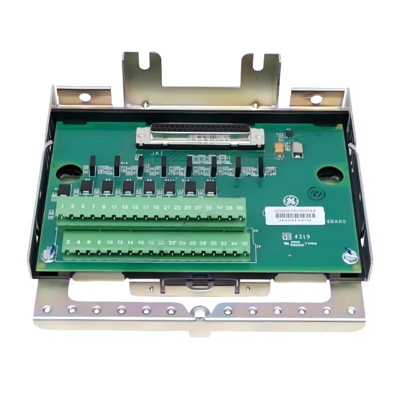
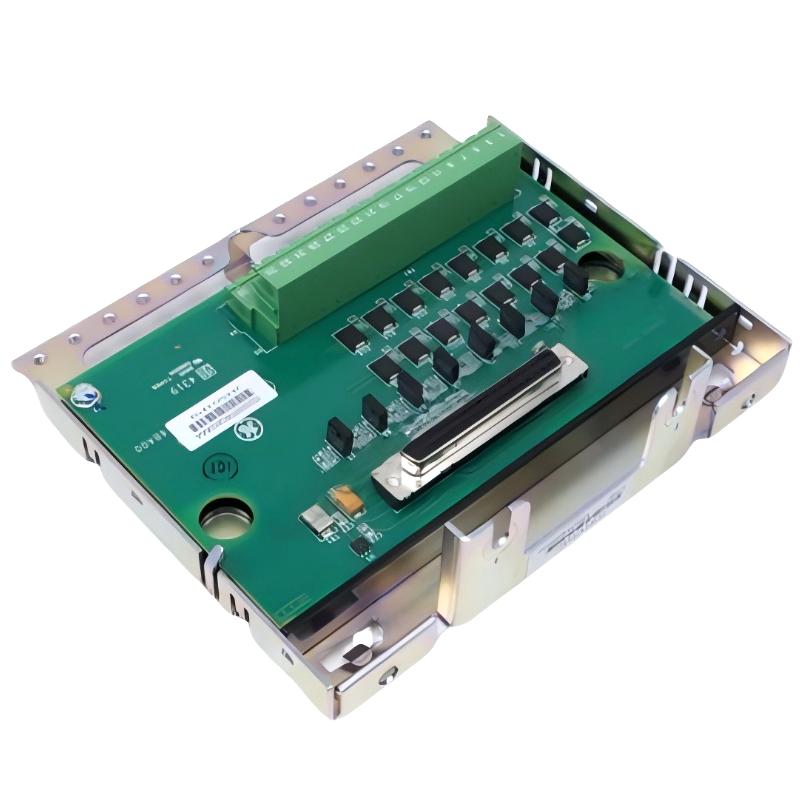
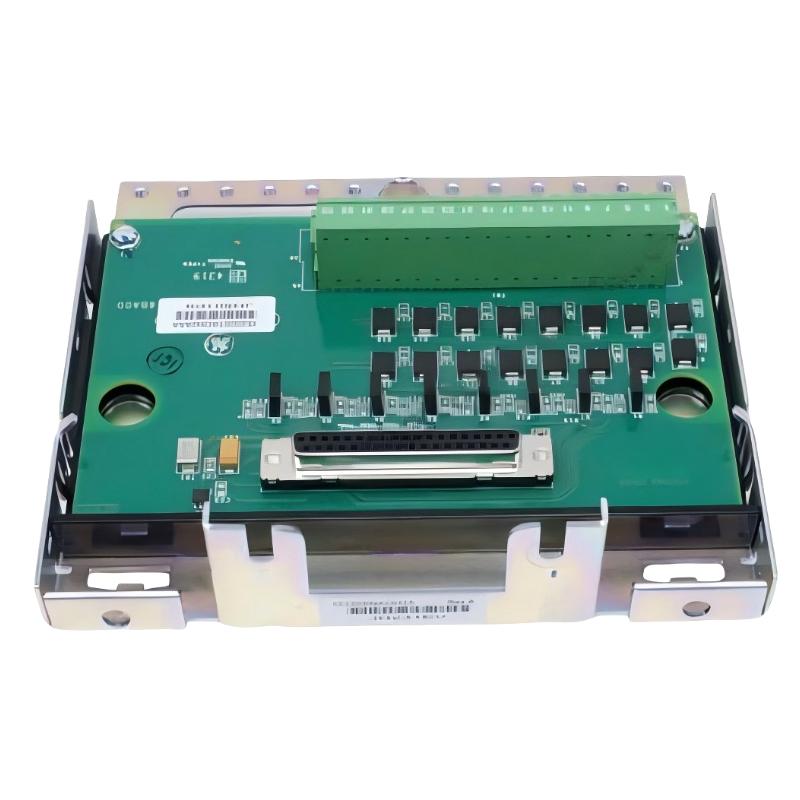
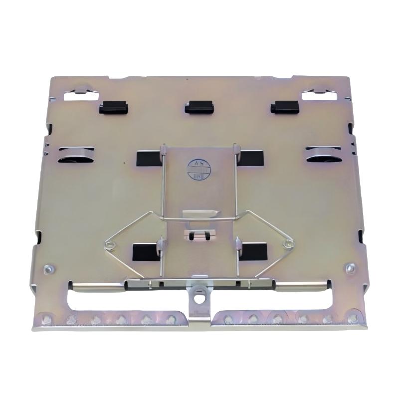
- GE
- IS230SNAOH2A IS200STAOH2AAA
- Analog Output Terminal Block
- USA
- 130 × 140 × 40 mm
- 0.35 kg
- Xiamen, China
- New & In Stock
- T/T, PayPal, Western Union
- 1 Year
- 1-3 Working Days
- DHL, UPS, TNT, FedEx and EMS.
- 24-Hour Service
- COO
- 8
Our advantage

Global Logistics
We have a 10-year logistics and express cooperation agreement, so our products can be shipped to any place in the world.

Brand new and original
Our products are imported in bulk from the place of origin. Because of the cooperative relationship, our products are all original and 100% new.

24-hour service
We provide 7*24 hours service to our customers. We will be there whenever you need us.

Price advantage
All our products are priced very favorably because we have our own warehouse and supply.
| Company Information | |||
| [email protected] | |||
| Mobile | +8615980777398 | ||
| +8615980777398 | |||
| 15980777398 |
Product Overview
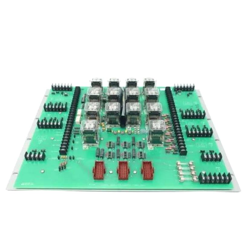
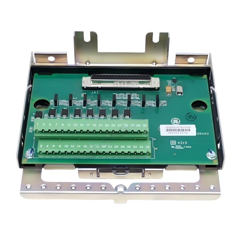
The GE IS230SNAOH2A / IS200STAOH2AAA Analog Output Terminal Block is an industrial control interface component intended for use in compatible GE automation systems. Designed for analog output wiring applications, this type of terminal block provides an organized connection point between control-system output circuitry and external field devices. It supports the wiring infrastructure required to transfer control commands from the automation system to equipment that responds to analog signals.
Analog output interfaces are widely used in industrial process control, where equipment must be adjusted continuously rather than simply switched ON or OFF. Depending on the system configuration, analog commands may be used to regulate valve position, adjust a compatible drive’s speed reference, control an actuator interface, or transmit a setpoint to another control device. Reliable wiring and correct terminal connections are essential to ensure that the intended command reaches the receiving equipment.
The model designations IS230SNAOH2A and IS200STAOH2AAA are associated with the product identification supplied for this terminal block. Before ordering, installation, or replacement, the relationship between the two identifiers should be confirmed against the installed hardware and its applicable configuration records. Similar model designations do not, by themselves, establish interchangeability.
With listed dimensions of 130 × 140 × 40 mm and a weight of approximately 0.35 kg, this component can be assessed for physical fit, cabinet planning, and replacement logistics within a compatible industrial control assembly.
Technical Specifications
| Parameter | Specification |
|---|---|
| Manufacturer | General Electric (GE) |
| Model Identification | IS230SNAOH2A / IS200STAOH2AAA |
| Product Type | Analog Output Terminal Block |
| Product Family | GE IS200 / IS230 Series |
| Primary Function | Analog output signal wiring interface |
| Signal Category | Analog output |
| System Role | Connection interface for compatible output circuitry and field wiring |
| Typical Application | Industrial automation and process control |
| Dimensions | 130 × 140 × 40 mm |
| Weight | 0.35 kg |
| Installation | Compatible GE control equipment |
| Electrical Characteristics | Confirm against the applicable hardware documentation |
Note: The supported output signal range, channel count, terminal assignments, electrical ratings, isolation characteristics, and exact compatibility requirements must be verified for the specific hardware configuration.
Function and Working Principle
1. Analog Output Signal Connection
An industrial controller generates commands based on programmed logic, operator settings, and process measurements. When a connected device requires a continuously adjustable reference, the control system may use an analog output signal to communicate the desired operating value.
An analog output terminal block provides the necessary connection points for the relevant wiring arrangement. Its purpose is to organize and connect the signal path; it should not automatically be assumed to perform the signal generation, scaling, or conversion functions of the associated electronic module.
2. Field Wiring Organization
The terminal block provides a structured interface for connecting conductors between compatible control hardware and external devices. Clear wiring organization helps technicians identify individual circuits, trace signals, inspect connections, and perform maintenance.
Correct terminal identification is particularly important in multi-channel control assemblies. Incorrect wiring can result in an unexpected field-device response, loss of control, or a mismatch between the command generated by the controller and the response observed in the process.
3. Interface With Output Electronics
In a typical automation arrangement, the controller calculates the required output command and the associated output electronics produce the electrical signal. The terminal block provides the designated connection path to the external circuit.
A simplified signal path is:
Controller Logic → Analog Output Electronics → Terminal Block → Field Device → Process Response
The actual arrangement for the IS230SNAOH2A / IS200STAOH2AAA must be confirmed using the documentation for the installed GE system. The exact signal route and associated hardware may vary by application.
4. Support for Continuous Control
Analog output wiring is useful when a process requires gradual changes in operating conditions. Depending on the receiving device and system configuration, an analog command may support valve positioning, equipment reference adjustments, or other continuous control functions.
The terminal block contributes to this arrangement by supporting the physical signal connections. Reliable performance also depends on the controller, output electronics, field wiring, receiving device, and configuration settings.
Role in Industrial Automation Systems
The GE Analog Output Terminal Block can form part of the output interface layer in an industrial control system. This layer connects electronic control functions to physical equipment that acts on process commands.
A complete system may include a controller, output electronics, terminal assemblies, field wiring, actuators, process instruments, and operator interfaces. Each component has a distinct role, and correct integration is necessary for the overall control loop to function as intended.
Typical system-level functions supported by an analog output terminal interface include:
- Organizing field wiring for output circuits.
- Providing connection points for compatible external devices.
- Supporting transmission of analog control commands.
- Simplifying circuit identification and maintenance.
- Helping technicians trace signal paths during troubleshooting.
- Supporting integration of field devices into automated process control.
The terminal block itself should not be treated as a standalone controller or as proof that a particular output signal type is supported. Its function depends on the associated electronics and approved system design.
Industrial Applications
Power Generation
Power generation facilities use control systems to manage auxiliary processes, equipment references, and other operating parameters. Analog output terminal interfaces can be part of the wiring infrastructure used to connect compatible output circuits to field equipment.
Suitability for a particular GE turbine or generator control system must be confirmed before the component is specified for a project.
Process Manufacturing
Chemical processing and general manufacturing operations often require continuous regulation of flow, pressure, temperature, and other variables. Compatible analog output circuits can communicate commands to equipment used in these processes.
The terminal block helps organize the connections required for these control functions.
Water and Wastewater Treatment
Water treatment facilities commonly use automated valves, dosing equipment, and other controlled devices. Where the control hardware and field device support a compatible analog interface, a suitable terminal block can form part of the signal path.
Industrial Machinery
Manufacturing equipment may require analog reference signals for drives, actuators, or dedicated controllers. Correct terminal wiring helps ensure that commands are routed to the intended equipment.
Utilities and Building Services
Industrial utility systems may use continuous control signals to adjust equipment operation in response to changing demand. Analog output wiring interfaces can support these applications when the installed hardware is correctly configured.
These examples describe general applications of analog output terminal interfaces. They do not establish that every application is approved for the specific GE component without verification.
Installation and System Integration
Correct installation requires verification of the component identity, associated electronics, and wiring arrangement. The product name and dimensions alone are not sufficient to establish electrical compatibility.
Verify the Part Number
Before installation, confirm the complete identification supplied for the component:
- IS230SNAOH2A
- IS200STAOH2AAA
Check the markings on the installed hardware and compare them with the system’s configuration records. If the identifiers refer to different assemblies or revisions in the specific installation, resolve that discrepancy before proceeding.
Review the Wiring Diagram
Identify the output circuits, associated electronics, field devices, conductor labels, and terminal assignments using the applicable system documentation.
Do not infer terminal numbers, signal polarity, output range, or channel mapping from physical appearance. Incorrect connections can cause unexpected device behavior or damage to connected equipment.
Follow Electrical Safety Procedures
Before handling the terminal block, follow the site’s approved isolation and lockout/tagout procedures. Confirm that the relevant circuits are in a safe state before disconnecting conductors or removing components.
For equipment that is part of a continuously operating process, any work should follow the facility’s maintenance planning and change-control procedures.
Inspect Mechanical Fit and Connections
The listed dimensions are 130 × 140 × 40 mm, and the listed weight is 0.35 kg. Confirm that the component fits the intended mounting position and leaves adequate clearance for wiring and maintenance access.
Inspect connectors, terminals, mounting points, and conductors for signs of damage, corrosion, contamination, or mechanical stress.
Confirm Output Compatibility
Verify that the associated output electronics and receiving device are compatible with the intended circuit. The output signal type, electrical range, load requirements, and grounding arrangement must be established from the applicable documentation.
Do not connect the terminal block to a field device solely because both are described as analog output components.
Commission the Installation
After installation, compare the completed wiring with the approved diagram and verify the relevant output configuration. Where authorized, test the circuit using the specified commissioning procedure and confirm that the receiving device responds as expected.
Check alarms, interlocks, scaling, and control direction before returning the equipment to normal service.
Troubleshooting Guide
Problems in an analog output circuit may originate in the controller, output electronics, terminal block, field wiring, or receiving device. Troubleshooting should follow the entire signal path.
No Output Response
If a connected device does not respond to a control command, inspect:
- Controller status and output command.
- Associated output module status.
- Terminal block seating and connector condition.
- Field wiring continuity and terminal identification.
- Receiving-device power and operating status.
- Configuration settings and relevant interlocks.
- System diagnostic messages.
A missing response does not necessarily mean the terminal block has failed. The controller may not be issuing a command, or the receiving device may have a separate fault.
Incorrect Device Response
If the field device responds but moves to an unexpected position or operating value, check the controller’s output scaling, configured engineering units, command limits, and receiving-device input requirements.
Also verify that the correct output circuit is connected to the intended device. A channel-mapping or wiring error can cause a valid command to reach the wrong destination.
Intermittent Operation
Intermittent output problems can be associated with loose terminals, damaged conductors, connector wear, vibration, contamination, or faults in the associated electronics.
Inspect the wiring and connection points under approved safe-work conditions. Review diagnostic history to determine whether the problem occurs at a particular operating condition or during equipment movement.
Unstable Output Behavior
An unstable field-device response may be caused by fluctuating controller commands, electrical interference, grounding issues, wiring defects, or a problem with the receiving device.
Compare the commanded value with the actual response using the approved diagnostic procedure. This helps distinguish a control-logic problem from a wiring or hardware issue.
Hardware Alarm
When the control system reports a hardware or interface alarm, record the exact diagnostic information before resetting or replacing components. Verify the installed model, revision, connections, and associated module status.
Follow the diagnostic procedure for the host GE control platform rather than relying on generic assumptions about the terminal block.
Maintenance Recommendations
Preventive maintenance helps preserve reliable connections and makes future fault diagnosis easier.
Inspect terminal connections: Check accessible terminals and connectors for looseness, corrosion, contamination, and signs of overheating.
Maintain wiring identification: Keep terminal labels and conductor markers legible and consistent with the current wiring diagrams.
Check mechanical condition: Inspect mounting points, housings, and connectors for damage or signs of excessive vibration.
Maintain cabinet conditions: Keep the control enclosure within the environmental limits specified for the installed system.
Record recurring faults: Document output alarms, intermittent behavior, replacement history, and commissioning results.
Verify the entire circuit: When a fault occurs, check the controller command, output electronics, terminal connections, wiring, and receiving device before concluding that the terminal block is defective.
All maintenance and testing should follow the approved procedures for the installed equipment and operating process.
Compatible System Components
An analog output terminal block generally operates as part of a wider control and field-wiring arrangement. Depending on the application, the system may include the following functional components.
| Component | General Function |
|---|---|
| GE IS230SNAOH2A / IS200STAOH2AAA | Analog output terminal interface identified for this product |
| Control Processor | Executes control logic and determines required commands |
| Compatible Analog Output Electronics | Generates the configured analog output signal |
| Field Wiring | Transfers the signal to the receiving equipment |
| Actuator or Control Device | Responds to the analog command |
| Power Supply | Provides power to components that require it |
| Operator Interface | Displays process conditions, commands, and alarms |
| Engineering and Diagnostic Tools | Support configuration and fault analysis |
This is a functional overview, not a confirmed list of directly compatible GE part numbers. Specific companion modules and approved combinations must be verified against the installed control platform.
Replacement and Procurement Considerations
When sourcing the GE IS230SNAOH2A / IS200STAOH2AAA Analog Output Terminal Block, accurate identification is more important than visual similarity.
Before purchasing, confirm:
- The complete part number and applicable revision.
- The relationship between the two supplied model identifiers.
- The installed GE control platform.
- The associated output electronics.
- Terminal layout and wiring configuration.
- Output signal and receiving-device requirements.
- Mounting dimensions and installation constraints.
- Any required configuration or commissioning procedures.
The listed physical dimensions are 130 × 140 × 40 mm, with a listed weight of 0.35 kg. These measurements are useful for cabinet layout, spare-parts inventory, and replacement logistics.
A terminal block should not be assumed to be interchangeable with another assembly simply because it has a similar appearance or supports an analog output application. Confirm electrical and mechanical compatibility before installing a replacement.
Technical FAQs
What is the GE IS230SNAOH2A / IS200STAOH2AAA?
It is identified in the supplied product information as a GE Analog Output Terminal Block for compatible industrial control applications.
What does an analog output terminal block do?
It provides connection points for the wiring associated with analog output circuits. The associated output electronics generate the signal, while the terminal block supports its connection to the relevant field wiring.
Can it be used to control valves or drives?
Only when the installed output hardware, terminal interface, and receiving device have compatible electrical characteristics and are approved for the intended application. The signal range and wiring must be verified before use.
What are its dimensions?
The listed dimensions are 130 × 140 × 40 mm.
How much does it weigh?
The listed weight is approximately 0.35 kg.
Are IS230SNAOH2A and IS200STAOH2AAA interchangeable model numbers?
Their relationship should be confirmed from the installed hardware markings and applicable system documentation. The two identifiers should not be assumed to represent interchangeable revisions or equivalent assemblies without verification.
What causes an analog output circuit to fail?
Possible causes include incorrect wiring, loose connections, a missing control command, configuration errors, faults in the associated output electronics, or a problem with the receiving device.
Can another GE terminal block be used as a replacement?
Not automatically. Confirm the full part number, terminal arrangement, electrical characteristics, associated hardware, and host-system requirements before substituting a different assembly.
Conclusion
The GE IS230SNAOH2A / IS200STAOH2AAA Analog Output Terminal Block is an industrial wiring interface intended to support analog output connections in a compatible GE control system. Properly integrated terminal interfaces help organize field wiring and provide a structured path for control commands to reach external equipment.
With listed dimensions of 130 × 140 × 40 mm and a weight of 0.35 kg, the component can be evaluated for physical fit and replacement planning. Reliable operation depends on accurate part identification, compatible output electronics, correct terminal wiring, and thorough commissioning.
For procurement and maintenance, verify the complete model designation and its relationship to the installed assembly before replacement. Careful wiring inspection, systematic troubleshooting, and accurate maintenance records help maintain dependable signal connections and stable industrial control performance.