

ProductPRODUCT
Featured products
Contact Us
- GE
- IS220PAOCH1BE
- Analog Input/Output Module
- USA
- 178 x 120 x 50 mm
- 1.2 kg
- Xiamen, China
- New & In Stock
- T/T, PayPal, Western Union
- 1 Year
- 1-3 Working Days
- DHL, UPS, TNT, FedEx and EMS.
- 24-Hour Service
- COO
- 4
Our advantage

Global Logistics
We have a 10-year logistics and express cooperation agreement, so our products can be shipped to any place in the world.

Brand new and original
Our products are imported in bulk from the place of origin. Because of the cooperative relationship, our products are all original and 100% new.

24-hour service
We provide 7*24 hours service to our customers. We will be there whenever you need us.

Price advantage
All our products are priced very favorably because we have our own warehouse and supply.
| Company Information | |||
| [email protected] | |||
| Mobile | +8615980777398 | ||
| +8615980777398 | |||
| 15980777398 |
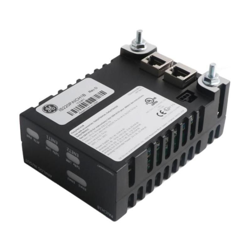
Product Overview
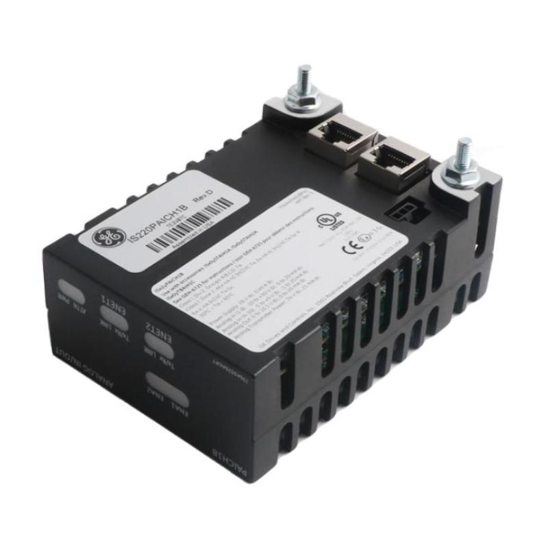
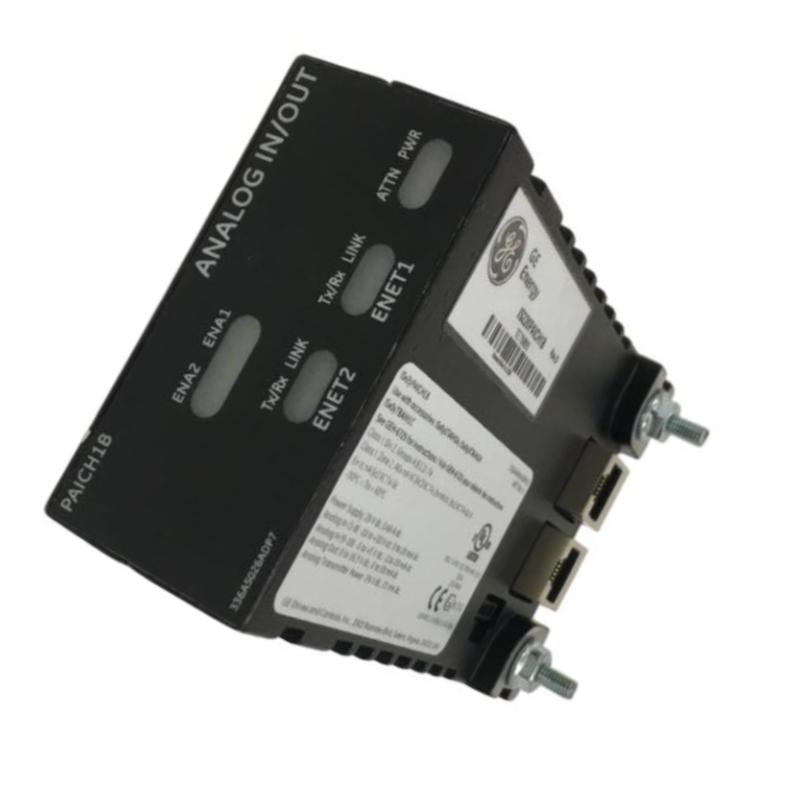
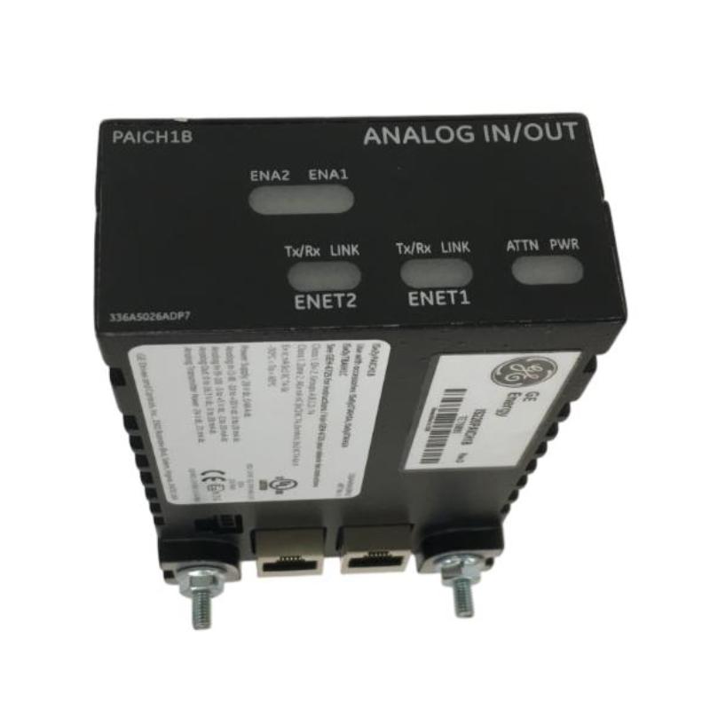
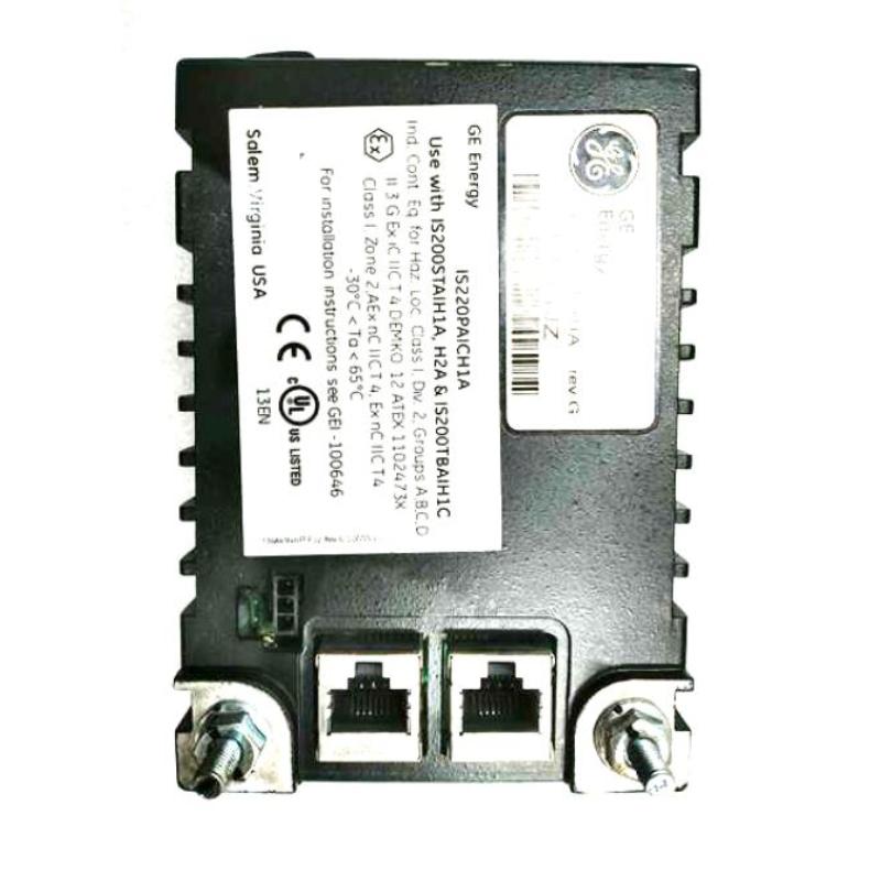
The GE IS220PAOCH1BE Analog Input/Output Module is an industrial automation interface component designed to connect analog field signals with a compatible GE control system. As an analog input/output module, it can form part of the signal interface layer between field instrumentation, process equipment, and the higher-level control architecture.
Modern industrial processes depend on continuous measurements and variable control signals. Unlike discrete signals that normally represent simple states such as ON or OFF, analog signals can represent continuously changing process conditions and control commands. These signals may be associated with temperature, pressure, flow, level, position, speed, process variables, or other instrumentation functions.
The IS220PAOCH1BE is identified as an Analog Input/Output Module and has listed physical dimensions of 178 × 120 × 50 mm, with a weight of approximately 1.2 kg. Its physical size and weight should be considered when planning cabinet installation, module replacement, wiring access, transportation, and maintenance procedures.
Within a compatible GE industrial automation architecture, an analog interface module can provide an important connection between field-level equipment and the control system. The controller determines how process information should be interpreted and how equipment should respond, while the I/O interface provides the electrical path between the control architecture and field devices.
A simplified system relationship can be represented as:
Field Instrumentation → Analog I/O Interface → Control System → Analog Control Signal → Field Equipment
The exact electrical configuration of the IS220PAOCH1BE should always be verified against the applicable hardware revision and system documentation before installation. Specific channel assignments, signal ranges, terminal arrangements, isolation characteristics, and electrical ratings should not be assumed solely from the product designation.
Technical Specifications
| Parameter | Specification |
|---|---|
| Manufacturer | General Electric (GE) |
| Model | IS220PAOCH1BE |
| Product Type | Analog Input/Output Module |
| Product Family | GE IS220 Series |
| Primary Function | Analog signal interfacing |
| Signal Direction | Field-to-control and control-to-field interface |
| Application | Industrial automation and process control |
| Interface Role | Analog field signal and control interface |
| Dimensions | 178 × 120 × 50 mm |
| Weight | 1.2 kg |
| Installation | Compatible GE industrial control equipment |
| Typical Applications | Process monitoring, instrumentation, control, equipment regulation |
Specification note: Exact input/output channel count, signal types, operating ranges, load characteristics, electrical ratings, terminal assignments, isolation, excitation, accuracy, and diagnostic functions should be confirmed for the actual IS220PAOCH1BE hardware revision and host-system configuration.
Understanding the GE IS220PAOCH1BE
The GE IS220PAOCH1BE is an analog input/output interface module intended for use within a compatible GE industrial control environment.
Industrial automation systems typically contain several layers. Sensors and transmitters interact with the physical process, I/O equipment transfers electrical information, controllers execute programmed logic, and operator interfaces display process conditions.
The analog I/O layer is particularly important because many industrial variables are continuous.
For example, a process temperature may gradually rise or fall rather than simply changing between two states. A control valve may need to move proportionally rather than only open or close. A pump or other process device may require a variable command based on the current process condition.
The analog interface provides the connection required for these types of applications.
A typical control relationship can be represented as:
Process → Sensor → Analog Input → Controller → Analog Output → Field Device → Process
The exact configuration depends on the application and installed control architecture.
Analog Input and Output Architecture
Analog Input Function
An analog input path allows a compatible control system to receive continuously variable information from field instrumentation.
Typical process variables can include:
- Temperature
- Pressure
- Flow
- Level
- Position
- Speed
- Equipment feedback
- Process concentration
- Valve position
- Other continuously varying measurements
The field instrument produces an electrical signal corresponding to the measured process condition. The analog interface then provides the connection between the field signal and the control system.
The controller can use this information for:
- Process monitoring
- Alarm generation
- Closed-loop control
- Equipment diagnostics
- Trend analysis
- Operator displays
- Process optimization
Analog Output Function
Analog output paths allow a control system to send variable commands toward compatible field equipment.
Depending on the system application, analog control signals may be used for:
- Valve positioning
- Actuator commands
- Speed references
- Process regulation
- Dosing control
- Equipment control
- Instrumentation interfaces
The actual output signal characteristics must be verified for the installed configuration.
Role in Industrial Automation
The IS220PAOCH1BE can function as part of a larger industrial control architecture.
A typical automation system may contain:
Field Devices → I/O Modules → Controller → Engineering System → HMI / SCADA
The field devices provide measurements or receive control commands. The I/O system provides the electrical interface. The controller executes the programmed application. The operator interface presents process information and equipment status.
An analog input/output module therefore provides a bridge between the physical process and the digital control environment.
For example, a process transmitter may provide a measurement to the control system. The controller compares the measured value with a desired operating condition. Based on the control strategy, it calculates an output command. The corresponding analog output is then transferred toward the appropriate field equipment.
This creates a continuous feedback loop between the automation system and the process.
Signal Acquisition and Processing
Reliable analog control begins with accurate signal acquisition.
A typical signal path may include:
Sensor → Transmitter → Field Cable → IS220PAOCH1BE → Controller
Several factors can affect signal quality during this process.
These include:
- Cable condition
- Electrical interference
- Grounding
- Shielding
- Terminal connections
- Sensor condition
- Transmitter configuration
- Environmental conditions
- Software scaling
For this reason, an analog I/O module should not be considered independently from the rest of the measurement system.
If a process value appears incorrect, technicians should inspect the entire signal path before replacing the module.
Analog Output and Equipment Control
The output side of an analog interface can be used to communicate continuously variable commands to field equipment.
A simplified output path is:
Controller → IS220PAOCH1BE → Field Wiring → Receiving Device → Equipment
For example, the controller may calculate that a control element needs to increase its operating level. The corresponding output command is transferred through the analog interface and received by compatible field equipment.
Potential applications include:
Control Valve Regulation
Analog control can be used to adjust valve position according to process requirements.
Actuator Positioning
Variable commands can be used with compatible actuators where proportional positioning is required.
Drive References
Certain industrial drive systems can use analog reference signals for speed or process commands when configured accordingly.
Dosing Systems
Analog output signals can be used to regulate compatible dosing equipment according to a calculated process requirement.
The actual application depends on the receiving equipment and system configuration.
Industrial Applications
Power Generation
Power-generation systems rely on continuous measurement of numerous operating variables. Analog instrumentation can provide information about pressure, temperature, flow, and other equipment conditions.
An appropriate analog I/O interface can incorporate these measurements into a larger control architecture.
Process Manufacturing
Chemical, petrochemical, pharmaceutical, and other process industries use analog signals extensively.
Typical applications include:
- Process monitoring
- Temperature control
- Pressure regulation
- Flow control
- Level management
- Equipment feedback
- Process optimization
Water and Wastewater Treatment
Water treatment facilities often monitor pumps, tanks, flow systems, pressure, and other process variables continuously.
Analog I/O systems can provide the interface needed to incorporate these measurements and control commands into the automation system.
Industrial Utilities
Boilers, cooling systems, compressed-air equipment, pumps, and other utilities may rely on continuously variable measurements and control signals.
An analog I/O module can provide an interface between utility equipment and the control system.
Manufacturing Equipment
Industrial machines may use analog sensors and variable control commands for temperature, pressure, position, speed, or other process conditions.
The module can therefore be considered within compatible manufacturing automation architectures where analog signal interfacing is required.
Physical Characteristics
The GE IS220PAOCH1BE has listed dimensions of:
178 × 120 × 50 mm
The listed weight is:
1.2 kg
These specifications are important for mechanical installation planning.
The module should not be evaluated only by its enclosure dimensions. The complete installation also requires sufficient space for connectors, field wiring, cable routing, maintenance access, and adjacent equipment.
When planning a replacement, technicians should verify:
- Mounting space
- Installation orientation
- Connector accessibility
- Wiring clearance
- Cable routing
- Maintenance access
- Environmental conditions
- Adjacent equipment
The 1.2 kg listed weight should also be considered when handling the module during installation and replacement.
Installation Guidelines
1. Confirm the Model
Before installation, verify the complete identification:
GE IS220PAOCH1BE
The full model designation should be compared with the existing module and the approved system configuration.
2. Inspect the Module
Check the module for visible damage before installation.
Inspect:
- Housing
- Connectors
- Contacts
- Mounting areas
- Cable interfaces
- Signs of overheating
- Contamination
- Moisture exposure
3. Verify System Compatibility
Confirm that the module is intended for the applicable GE control architecture and installation location.
A module with similar dimensions may have a different electrical function and should not automatically be treated as interchangeable.
4. Verify Field Wiring
Field wiring should be checked against the approved system documentation.
Incorrect connections can produce inaccurate measurements, unexpected equipment behavior, or loss of signal.
5. Check Grounding and Shielding
Appropriate grounding and shielding should be maintained according to the system design.
This is particularly important for analog signals because electrical interference can influence measurement stability and control performance.
6. Confirm Software Configuration
The control system configuration should correspond to the installed hardware.
Signal scaling, engineering units, alarm limits, control parameters, and other application settings should be reviewed before commissioning.
Wiring and EMC Considerations
Analog signal quality can be affected by electromagnetic interference.
Potential sources include:
- Motors
- Variable-frequency drives
- Contactors
- High-current conductors
- Switching power supplies
- Relay circuits
- Poor grounding
- Improper cable routing
Good installation practices include keeping sensitive signal wiring appropriately separated from high-power conductors.
Where required by the system design, shielded cables should be used and terminated according to the applicable grounding strategy.
Technicians should also inspect:
- Terminal tightness
- Connector condition
- Cable insulation
- Cable routing
- Shield continuity
- Ground connections
A stable electrical installation helps improve the reliability of the analog measurement and control system.
Commissioning Procedure
A systematic commissioning process can reduce the risk of configuration and wiring problems.
Step 1: Verify Hardware
Confirm the complete IS220PAOCH1BE identification and inspect the module.
Step 2: Verify Mechanical Installation
Check mounting, physical clearance, connector access, and cable routing.
Step 3: Verify Field Connections
Check all analog input and output connections against the applicable system documentation.
Step 4: Check Controller Configuration
Confirm that the control system is configured for the installed hardware.
Step 5: Verify Input Signals
Where applicable, compare received process values with known or expected operating conditions.
Step 6: Verify Output Commands
Where analog output functions are configured, perform controlled testing to confirm that the receiving equipment responds appropriately.
Step 7: Check Scaling
Confirm that raw signal information corresponds correctly to the intended engineering units.
Step 8: Test Alarms and Interlocks
Verify applicable alarm thresholds, permissives, and interlocks before normal automatic operation.
Step 9: Record Results
Document the module identification, configuration, wiring checks, and commissioning results for future maintenance.
Troubleshooting the IS220PAOCH1BE
Analog I/O problems should be investigated systematically.
No Input Signal
If the control system does not receive an expected analog measurement, check:
- Sensor
- Transmitter
- Field cable
- Terminal connections
- Module connectors
- Module status
- Controller configuration
- Associated diagnostics
The absence of a signal does not necessarily mean that the module has failed.
Incorrect Input Value
An incorrect analog value may be caused by:
- Sensor calibration
- Transmitter configuration
- Wiring errors
- Incorrect scaling
- Grounding problems
- Electrical interference
- Configuration mismatch
- Hardware problems
Comparing the control-system value with an independent reference can help determine where the problem is located.
Unstable Analog Value
An unstable reading may result from:
- Electrical interference
- Loose connections
- Cable damage
- Poor grounding
- Sensor instability
- Process fluctuations
- Incorrect configuration
Signal quality should be checked before replacing the module.
No Analog Output
If an expected output command is not reaching the field equipment, inspect:
- Controller logic
- Output configuration
- Module status
- Module connectors
- Field wiring
- Terminal connections
- Receiving-device configuration
- Field equipment
This layered approach helps separate control-logic problems from hardware and wiring problems.
Field Device Responds Incorrectly
If the analog output exists but the field equipment responds incorrectly, verify:
- Output scaling
- Receiving-device input configuration
- Wiring polarity or connection arrangement where applicable
- Field-device calibration
- Process control logic
- Mechanical condition of the equipment
Preventive Maintenance
Regular inspection can help maintain stable analog I/O operation.
Inspect Connectors
Check connectors for looseness, contamination, corrosion, or physical damage.
Inspect Wiring
Field cables should be inspected for:
- Damaged insulation
- Loose terminals
- Moisture
- Excessive bending
- Mechanical wear
- Poor routing
Monitor Process Trends
Long-term trends can reveal gradual changes in sensor behavior, process conditions, or equipment response.
Unexpected drift may justify investigation before a complete failure occurs.
Maintain Cabinet Conditions
The module should be operated within the environmental conditions appropriate for the actual installation.
Control cabinets should be protected from excessive:
- Dust
- Moisture
- Heat
- Vibration
- Contamination
Inspect Associated Field Devices
A functioning analog interface cannot compensate for a damaged sensor, transmitter, actuator, or other field device.
Preventive maintenance should therefore cover the complete signal chain.
Control Loop Integration
One of the important applications of analog I/O is closed-loop process control.
A simplified control loop can be represented as:
Process → Sensor → Analog Input → Controller → Analog Output → Field Device → Process
The controller continuously evaluates the process condition and determines whether an output adjustment is required.
For example:
- A sensor measures a process variable.
- The measurement enters the control architecture.
- The controller compares the process value with the desired setpoint.
- The control algorithm calculates an output.
- The analog output interface communicates the command.
- The field device changes the process condition.
- The sensor detects the new condition.
- The cycle repeats.
This feedback mechanism allows industrial processes to be regulated continuously.
Signal Scaling and Engineering Values
Analog systems require correct interpretation of electrical signals.
The control system may convert an electrical input into an engineering value such as:
- Temperature
- Pressure
- Flow
- Level
- Position
- Speed
- Percentage
Similarly, an output command may be converted from a controller value into an appropriate field signal.
Incorrect scaling can result in an apparently functional I/O system displaying or producing the wrong physical value.
For this reason, commissioning should verify both the electrical behavior and the corresponding engineering-unit interpretation.
Exact signal ranges and scaling parameters should be confirmed for the actual application.
Replacement and Compatibility Considerations
When replacing an existing GE IS220PAOCH1BE, technicians should verify the complete identification before disconnecting the original module.
Important information includes:
- Full model number
- Hardware revision
- Existing installation position
- Connector configuration
- Field wiring
- Controller configuration
- Associated field equipment
- Application software configuration
The replacement module should be checked against the original installation before field connections are transferred.
Physical similarity alone is not sufficient to establish compatibility. The electrical function and system requirements must also match.
Before commissioning a replacement, document the original wiring and software configuration wherever possible.
System Integration
The IS220PAOCH1BE may form part of a larger industrial automation system containing several functional layers.
| System Component | Typical Role |
|---|---|
| Field Sensor | Measures process conditions |
| Transmitter | Provides a compatible electrical signal |
| IS220PAOCH1BE | Analog input/output interface |
| Control Processor | Executes control logic |
| Engineering System | Provides configuration and diagnostics |
| HMI | Displays process information |
| SCADA System | Provides supervisory monitoring |
| Field Actuator | Responds to analog control commands |
The exact components and architecture depend on the installed GE control platform.
Cabinet and Mechanical Planning
The listed 178 × 120 × 50 mm dimensions should be incorporated into cabinet and equipment planning.
Mechanical planning should account for more than the module body.
Consider:
- Module footprint
- Connector clearance
- Field-cable access
- Cable bending
- Adjacent equipment
- Heat dissipation
- Maintenance access
- Module removal space
- Wiring separation
The listed 1.2 kg weight should also be considered during transportation, handling, and replacement.
For systems with multiple modules, engineers should consider the combined physical and wiring requirements of the complete assembly.
Key Advantages
Analog Input/Output Interface
The IS220PAOCH1BE provides a dedicated interface for analog process signals and compatible control commands.
Integration with Industrial Automation
The module can form part of a larger GE control architecture connecting field instrumentation with controller-level functions.
Supports Continuous Process Information
Analog signals allow control systems to work with continuously changing measurements and control values.
Suitable for Process Applications
Analog I/O technology is widely applicable to process monitoring, equipment regulation, instrumentation, and closed-loop control.
Compact Industrial Construction
The listed dimensions of 178 × 120 × 50 mm provide a defined mechanical envelope for installation and replacement planning.
Practical Replacement Reference
The listed 1.2 kg weight and physical dimensions can assist maintenance teams with handling, inventory, transportation, and cabinet planning.
Technical FAQs
What is the GE IS220PAOCH1BE?
The GE IS220PAOCH1BE is an Analog Input/Output Module designed to provide analog signal interface functionality within a compatible GE industrial control system.
What does an analog input/output module do?
An analog I/O module provides an interface between continuously variable field signals and the industrial control system. Depending on the configuration, it can support process measurements and variable control commands.
What are the dimensions of the IS220PAOCH1BE?
The listed dimensions are 178 × 120 × 50 mm.
How much does the IS220PAOCH1BE weigh?
The listed weight is approximately 1.2 kg.
What applications can use the IS220PAOCH1BE?
Analog I/O interfaces can be used in process control, power-generation systems, manufacturing, water treatment, utility systems, instrumentation, and other industrial automation applications where variable signals are required.
Can the IS220PAOCH1BE be used as a standalone PLC?
No. It is an Analog Input/Output Module intended to operate as part of a compatible control architecture rather than as a standalone PLC controller.
What causes unstable analog measurements?
Possible causes include electrical interference, poor grounding, damaged wiring, loose terminals, sensor problems, process fluctuations, or configuration errors.
What causes an analog output device not to respond?
Possible causes include incorrect control logic, configuration problems, wiring faults, receiving-device settings, power issues, or problems with the field equipment itself.
Can another IS220 module be used as a replacement?
A different IS220 module should not automatically be considered interchangeable. The complete part number, hardware revision, electrical function, connectors, and host-system requirements should be verified before replacement.
Should exact channel and signal specifications be assumed?
No. Exact channel count, signal ranges, electrical ratings, isolation, terminal assignments, and other detailed characteristics should be verified against the actual hardware documentation and system configuration.
Conclusion
The GE IS220PAOCH1BE Analog Input/Output Module is an industrial automation interface component designed to connect analog field instrumentation and compatible control equipment with a GE control architecture. Its role is to support the transfer of continuously variable process information and control signals between field devices and the automation system.
The module has listed dimensions of 178 × 120 × 50 mm and a weight of 1.2 kg, specifications that are important for cabinet design, replacement planning, equipment handling, and maintenance logistics.
Analog I/O plays a central role in modern industrial automation because many process variables require continuous measurement and proportional control. By providing an interface between field devices and control logic, an appropriate analog I/O module can contribute to process monitoring, equipment regulation, closed-loop control, alarms, diagnostics, and supervisory functions.
For installation or replacement, the complete GE IS220PAOCH1BE identification should be verified together with the applicable hardware revision and host-system configuration. Field wiring, grounding, signal scaling, controller configuration, and receiving-device compatibility should also be checked before commissioning.
Exact electrical characteristics should not be assumed solely from the product name. Channel configuration, signal ranges, terminal assignments, isolation, load requirements, and other detailed parameters should be confirmed for the actual installation.
When properly integrated into a compatible GE automation system, the IS220PAOCH1BE can provide an important analog interface between real-world industrial processes and the control functions responsible for monitoring and regulating those processes.