

ProductPRODUCT
Featured products
Contact Us
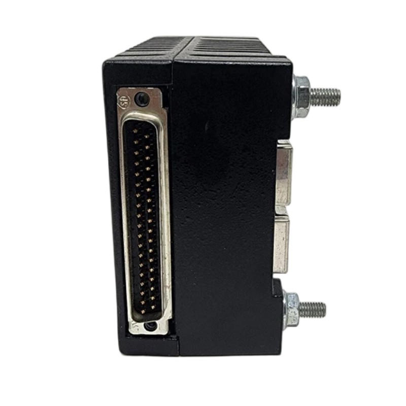
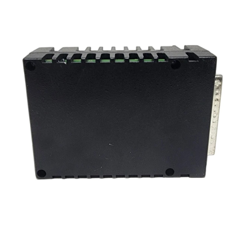
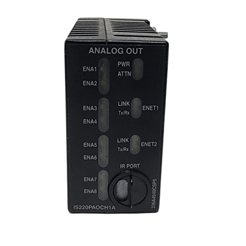
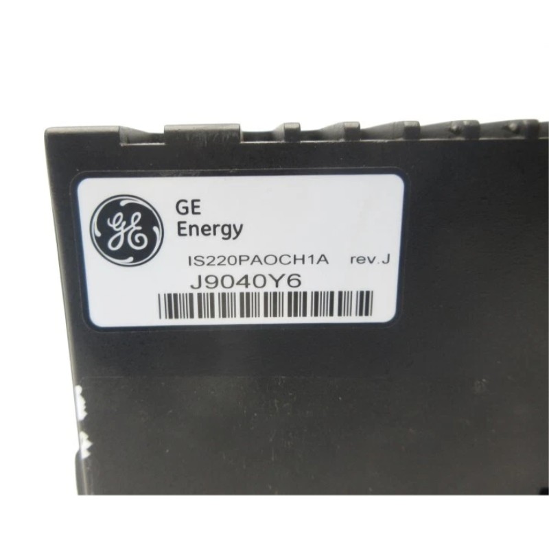
- GE
- IS220PAOCH1A
- Analog Output Module
- USA
- 122 x 82 x 60mm
- 0.38kg
- Xiamen, China
- New & In Stock
- T/T, PayPal, Western Union
- 1 Year
- 1-3 Working Days
- DHL, UPS, TNT, FedEx and EMS.
- 24-Hour Service
- COO
- 4
Our advantage

Global Logistics
We have a 10-year logistics and express cooperation agreement, so our products can be shipped to any place in the world.

Brand new and original
Our products are imported in bulk from the place of origin. Because of the cooperative relationship, our products are all original and 100% new.

24-hour service
We provide 7*24 hours service to our customers. We will be there whenever you need us.

Price advantage
All our products are priced very favorably because we have our own warehouse and supply.
| Company Information | |||
| [email protected] | |||
| Mobile | +8615980777398 | ||
| +8615980777398 | |||
| 15980777398 |
Product Overview
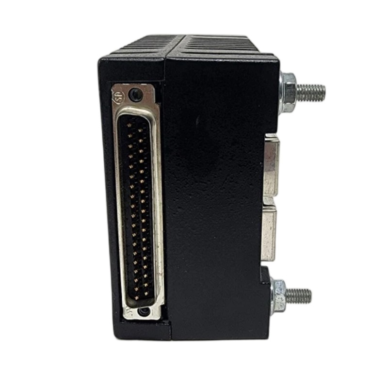
The GE IS220PAOCH1A Analog Output Module is an industrial automation interface module designed to provide analog output communication between a compatible GE control system and field-level equipment. It is intended for applications where continuously variable control signals are required to command or regulate industrial devices such as actuators, control elements, and other analog-responsive equipment.
Unlike a discrete output that provides a simple ON/OFF state, an analog output can represent a continuously varying command. This makes analog output interfaces important in process-control applications where equipment must respond proportionally to a controller-generated reference.
The GE IS220PAOCH1A is identified as an Analog Output Module with listed dimensions of 122 × 82 × 60 mm and a weight of approximately 0.38 kg. Its compact construction makes it suitable for integration into industrial control equipment where efficient use of panel and system space is important.
Within a larger automation architecture, the module serves as an interface between control logic and field devices. The controller determines the required process response, while the analog output module provides the corresponding electrical interface toward compatible field equipment.
A simplified control path can be represented as:
Control Logic → IS220PAOCH1A → Analog Output Signal → Field Device → Process
The exact signal type, output range, channel configuration, electrical ratings, and terminal assignments should be confirmed against the specific hardware revision and host-system configuration before installation.
Technical Specifications
| Parameter | Specification |
|---|---|
| Manufacturer | General Electric (GE) |
| Model | IS220PAOCH1A |
| Product Type | Analog Output Module |
| Product Family | GE IS220 Series |
| Primary Function | Analog output signal interface |
| Signal Direction | Control system to field equipment |
| Application | Industrial process control and automation |
| Interface Role | Controller-to-field-device interface |
| Dimensions | 122 × 82 × 60 mm |
| Weight | 0.38 kg |
| Installation | Compatible GE industrial control equipment |
| Typical Applications | Process control, actuator control, equipment regulation, industrial instrumentation |
Technical note: Exact output channel count, signal ranges, electrical ratings, isolation, load requirements, terminal assignments, diagnostic functions, and other detailed characteristics should be verified against the applicable IS220PAOCH1A hardware revision and system documentation.
What Is the GE IS220PAOCH1A?
The IS220PAOCH1A is a GE Analog Output Module used within a compatible industrial control architecture.
The purpose of an analog output interface is to translate a controller-generated command into an electrical signal that can be interpreted by an appropriate field device.
For example, a control system may determine that a valve should move toward a particular operating position. Instead of simply turning the valve fully ON or OFF, the controller can generate a variable output command. The analog output interface transfers this command toward the compatible field equipment.
This creates a closed relationship between control logic and physical process operation:
Process Measurement → Controller → Analog Output → Field Device → Process Response
The module itself is therefore an important interface layer between digital control logic and continuously variable physical equipment.
Analog Output Function
Converting Control Commands into Field Signals
An analog output module is designed to provide a continuously variable electrical output corresponding to a control command.
The control application may calculate an output value based on:
- Process measurements
- Setpoints
- Control algorithms
- Operator commands
- Equipment status
- Process limits
- Interlocks
- Sequencing logic
The resulting command is passed through the analog output interface toward the appropriate field device.
Proportional Equipment Control
Analog outputs are useful when equipment needs proportional control rather than simple switching.
Depending on the application, an analog output may be associated with:
- Control valves
- Actuators
- Speed references
- Process controllers
- Dosing equipment
- Positioning systems
- Instrumentation
- Other compatible analog-controlled devices
The actual field-device compatibility depends on the configured output signal and system design.
Continuous Process Regulation
Analog output signals can support continuous regulation of industrial processes.
For example, a control system may continuously adjust a field device based on changing process conditions. The output command can increase or decrease as the process moves away from or toward its desired operating point.
This type of control is common in applications where precise process regulation is more appropriate than discrete switching.
Role in Industrial Control Systems
The IS220PAOCH1A can occupy the output-interface layer of an industrial automation system.
A typical architecture may be represented as:
Sensors → Input Modules → Controller → Analog Output Module → Field Equipment
The controller executes the application logic and determines the required output. The analog output module then provides the interface through which the command reaches the field device.
This architecture allows a central control system to coordinate multiple pieces of industrial equipment.
For example, a process controller may monitor temperature through an input interface. If the measured temperature changes, the controller can calculate a new control command. The IS220PAOCH1A can then provide the appropriate analog output toward a compatible control device.
Typical Analog Output Applications
Control Valve Regulation
Process control valves often require variable command signals rather than simple ON/OFF switching.
An analog output interface can allow the control system to continuously adjust a valve according to the programmed process strategy.
Applications may include:
- Flow regulation
- Pressure control
- Temperature regulation
- Level control
- Process mixing
Motor and Drive References
Some industrial systems use analog reference signals to communicate speed or operating commands to compatible drive equipment.
The analog output can form part of the interface between the controller and the motor-control system.
Actuator Control
Industrial actuators may require variable positioning or command signals.
An analog output module can provide the electrical interface required for such equipment when the actuator and control system are designed to use a compatible analog signal.
Dosing and Process Equipment
Chemical dosing, material handling, and process equipment may require continuously variable control.
Analog output signals can be used to regulate compatible equipment according to the control application’s calculated command.
Analog Output Signal Path
A reliable analog output system involves several components.
A simplified signal path is:
Control Program → Controller → IS220PAOCH1A → Field Wiring → Receiving Device → Process Equipment
Each part of the path must operate correctly.
A problem at the controller can produce an incorrect command. A wiring problem can prevent the signal from reaching the field device. A field-device configuration problem can cause the receiving equipment to interpret the signal incorrectly.
Therefore, troubleshooting should examine the complete output path rather than automatically assuming that the analog output module is defective.
Installation Guidelines
Verify Module Identification
Before installation, verify the complete product designation:
GE IS220PAOCH1A
The model number should be checked against the system configuration and existing equipment.
Similar-looking industrial modules may perform different functions, so physical appearance should not be used as the only method of identification.
Inspect the Module
Before mounting or connecting the module, inspect it for:
- Physical damage
- Cracked or damaged housing
- Damaged connectors
- Bent contacts
- Contamination
- Moisture
- Signs of overheating
Any visible damage should be investigated before the module is placed into service.
Confirm System Compatibility
Verify that the IS220PAOCH1A is intended for the applicable GE control architecture and installation position.
The module should be matched to the correct system configuration before field wiring is connected.
Check Field Wiring
All output wiring should be checked against the approved electrical documentation.
Incorrect wiring may result in:
- No output signal
- Incorrect equipment response
- Unstable control
- Unexpected process behavior
- Potential equipment damage
Verify Grounding
Appropriate grounding practices should be followed according to the actual control-system design.
Good grounding can help reduce electrical interference and improve analog signal stability.
Wiring and Signal Integrity
Analog output signals can be sensitive to installation conditions.
Electrical interference can be introduced by nearby:
- Variable-frequency drives
- Motors
- Contactors
- High-current cables
- Switching equipment
- Power supplies
- Relay circuits
Signal cables should therefore be routed appropriately within the control cabinet and field installation.
Recommended practices include:
- Keep analog signal wiring away from high-power conductors where practical.
- Avoid unnecessary cable loops.
- Maintain secure terminal connections.
- Inspect cable insulation.
- Use appropriate shielding where required.
- Follow the system grounding design.
- Avoid routing analog signals through areas with excessive electromagnetic interference.
The exact shielding and grounding arrangement should follow the applicable system design rather than applying a generic connection method.
Commissioning Procedure
A structured commissioning process helps verify that the analog output system operates correctly.
Step 1: Confirm Hardware
Verify the IS220PAOCH1A model and inspect the module for physical damage.
Step 2: Check Installation
Confirm mounting, connectors, field wiring, grounding, and cable routing.
Step 3: Verify System Configuration
Confirm that the controller configuration corresponds to the installed analog output module.
Step 4: Check Output Configuration
Verify the configured output function, scaling, engineering units, and associated control parameters.
Step 5: Perform a Controlled Output Test
Where permitted by the application, test the output using a controlled operating condition.
The receiving field device should respond in accordance with the configured system design.
Step 6: Verify Process Response
Confirm that the field equipment responds correctly and that the process remains within safe operating limits.
Step 7: Test Alarms and Interlocks
Where applicable, verify that configured alarms, permissives, and interlocks respond correctly.
Step 8: Record Results
Record the installed module identification, configuration information, test conditions, and observed results for future maintenance.
Troubleshooting the GE IS220PAOCH1A
Troubleshooting should begin by identifying whether the problem originates in the control logic, output module, field wiring, or receiving equipment.
No Analog Output
If the expected analog command is not present, inspect:
- Controller status
- Control logic
- Module configuration
- Module connectors
- Field wiring
- Terminal connections
- Receiving equipment
- System diagnostics
A missing output does not automatically indicate a failed module.
Incorrect Output Value
An incorrect output can result from:
- Incorrect control logic
- Incorrect scaling
- Configuration errors
- Wiring problems
- Receiving-device configuration
- Electrical interference
- Hardware problems
The command value generated by the controller should be compared with the actual signal observed at the appropriate point in the output circuit.
Unstable Output
An unstable analog output may be associated with:
- Control-loop instability
- Electrical interference
- Poor wiring
- Loose terminals
- Grounding problems
- Receiving-device problems
- Configuration errors
The controller’s commanded value should be checked before concluding that the output interface is defective.
Field Device Does Not Respond
If the module appears to be generating an output but the field equipment does not respond, inspect the complete signal chain.
Check:
- Controller command
- Module configuration
- Output wiring
- Terminal connections
- Receiving-device input
- Field-device configuration
- Power supply to the receiving equipment
- Mechanical condition of the controlled device
This approach helps distinguish an electronic interface problem from a field-equipment problem.
Preventive Maintenance
Regular maintenance can improve the reliability of an analog output system.
Inspect Connectors
Check connectors periodically for:
- Loose connections
- Corrosion
- Contamination
- Mechanical damage
- Improper seating
Inspect Field Wiring
Look for damaged insulation, loose terminals, excessive bending, or cable degradation.
Monitor Output Trends
Where system monitoring is available, trend the commanded output values and compare them with expected process behavior.
Unexpected changes can provide an early indication of control-loop or field-equipment problems.
Inspect the Receiving Equipment
An analog output module may function correctly even when the connected field device has a mechanical or electrical fault.
Maintenance should therefore include the complete control path.
Maintain Cabinet Conditions
The control cabinet should be kept within the environmental conditions appropriate for the installed equipment.
Excessive dust, moisture, heat, vibration, or contamination can negatively affect electronic equipment.
Integration with Process Control Loops
The IS220PAOCH1A can participate in a closed-loop control strategy.
A simplified loop can be represented as:
Process → Sensor → Input Interface → Controller → IS220PAOCH1A → Field Device → Process
The controller continuously compares the process condition with the desired operating point and determines the required output.
For example, in a temperature-control application:
- A sensor measures process temperature.
- The input system transfers the measurement to the controller.
- The controller compares the measurement with the desired setpoint.
- The control algorithm calculates an output command.
- The IS220PAOCH1A provides the corresponding analog output.
- The field device adjusts the process.
- The process changes.
- The measurement cycle continues.
This feedback structure allows the automation system to maintain a process near its configured operating target.
Physical Dimensions and Cabinet Planning
The listed dimensions of the GE IS220PAOCH1A are:
122 × 82 × 60 mm
The listed weight is:
0.38 kg
These values should be considered during cabinet design, replacement planning, transportation, and inventory management.
The physical dimensions of the module are only one part of installation planning. Adequate space should also be provided for connectors, field wiring, cable routing, inspection, and maintenance.
Before installation, engineers should consider:
- Available mounting space
- Module orientation
- Connector accessibility
- Wiring clearance
- Cable bending requirements
- Adjacent equipment
- Heat management
- Service access
Replacement Considerations
When replacing an existing analog output module, verify the complete identification of the original equipment.
Important information includes:
- GE model number
- Hardware revision
- Installation location
- Connector arrangement
- Field wiring
- Controller configuration
- Associated field equipment
- Application software configuration
The replacement should be verified before transferring field connections.
A different GE IS220 module should not be treated as a direct replacement simply because its housing or dimensions appear similar.
The electrical function, system compatibility, signal requirements, and configuration must all be confirmed.
System-Level Diagnostics
A useful troubleshooting strategy is to divide the output system into several layers.
| Diagnostic Layer | Items to Check |
|---|---|
| Control Logic | Setpoints, commands, sequencing and control algorithms |
| Controller | Processor status and configuration |
| Output Module | Module status, connectors and diagnostics |
| Wiring | Terminals, cables, shielding and grounding |
| Receiving Device | Input configuration and power |
| Field Equipment | Mechanical and electrical response |
| Process | Actual process behavior and operating conditions |
This layered approach helps maintenance personnel isolate faults more efficiently.
For example, if the controller is producing the expected command but the receiving device does not respond, attention should shift toward the output circuit, wiring, receiving-device configuration, and field equipment.
Key Advantages
Dedicated Analog Output Interface
The IS220PAOCH1A provides an interface for communicating variable control commands from a compatible control system to field equipment.
Compact Design
With listed dimensions of 122 × 82 × 60 mm, the module can be incorporated into compact industrial control assemblies.
Supports Continuous Control
Analog outputs allow compatible equipment to receive variable commands rather than only discrete ON/OFF signals.
Suitable for Process Automation
The module can contribute to applications involving valves, actuators, process equipment, instrumentation, and other analog-controlled systems.
Integration with Industrial Control Architecture
The module operates as part of a larger automation system, connecting control logic with field-level equipment.
Technical FAQs
What is the GE IS220PAOCH1A?
The GE IS220PAOCH1A is an Analog Output Module designed to provide an interface between a compatible GE control system and analog-controlled field equipment.
What is the main function of an analog output module?
An analog output module provides continuously variable control signals from the automation system toward compatible field devices.
What are the dimensions of the IS220PAOCH1A?
The listed dimensions are 122 × 82 × 60 mm.
What is the weight of the IS220PAOCH1A?
The listed weight is approximately 0.38 kg.
Where can an analog output module be used?
Analog output interfaces can be used in applications involving control valves, actuators, process equipment, instrumentation, drive references, and other compatible devices requiring variable control signals.
Can the IS220PAOCH1A operate independently?
No. It is an interface module intended to operate as part of a compatible industrial control architecture rather than as a standalone PLC controller.
What can cause an incorrect analog output?
Possible causes include control-logic errors, incorrect scaling, configuration problems, wiring faults, electrical interference, receiving-device issues, or module-level problems.
What should be checked before replacing the module?
The complete model number, hardware revision, controller configuration, field wiring, connector arrangement, receiving-device requirements, and system compatibility should be checked before replacement.
Should exact electrical specifications be assumed from the model number?
No. Exact channel configuration, output range, load requirements, isolation, terminal assignments, and other electrical specifications should be verified against the applicable hardware documentation and system configuration.
Conclusion
The GE IS220PAOCH1A Analog Output Module is an industrial automation interface component designed to connect control-system output commands with compatible analog field equipment. It provides an important interface layer for applications requiring continuously variable control rather than simple discrete switching.
With listed dimensions of 122 × 82 × 60 mm and a weight of 0.38 kg, the module offers a compact physical format for integration into compatible GE industrial control systems.
The IS220PAOCH1A can contribute to applications involving process valves, actuators, instrumentation, equipment regulation, and other systems where analog control signals are required. Its effectiveness depends on the complete control loop, including the controller, output configuration, field wiring, receiving device, and controlled process.
For installation, commissioning, troubleshooting, or replacement, technicians should verify the complete GE IS220PAOCH1A identification and applicable hardware configuration. Exact output characteristics should be confirmed before field connections are made.
When properly integrated, the GE IS220PAOCH1A Analog Output Module provides a practical interface between industrial control logic and continuously variable field equipment, supporting reliable process regulation and automated control within compatible GE automation architectures.