

ProductPRODUCT
Featured products



Contact Us
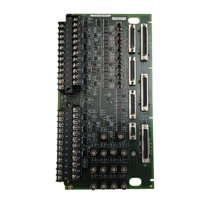
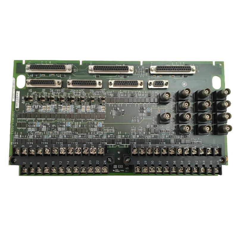
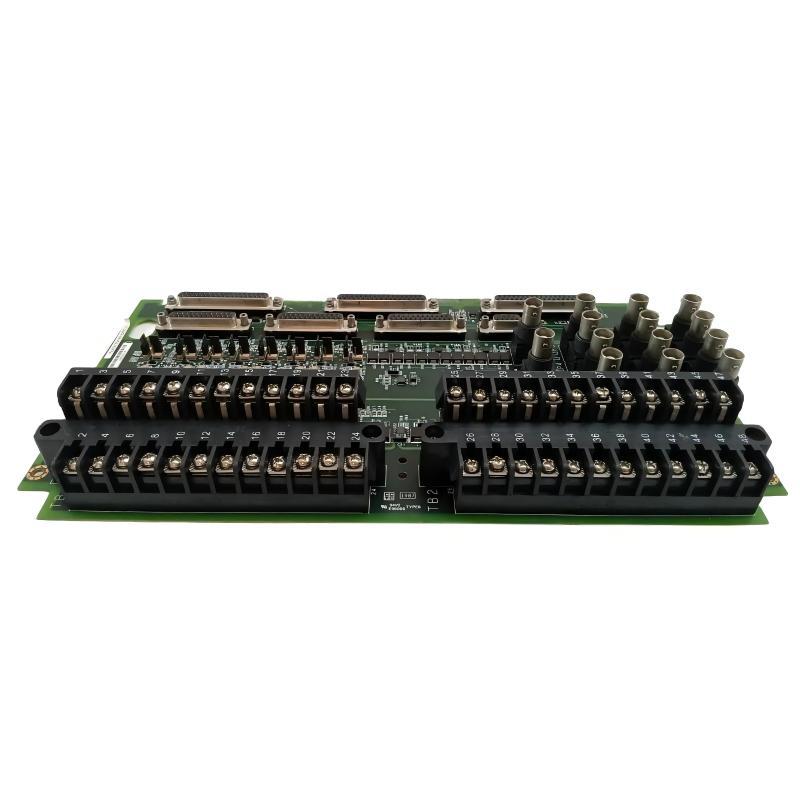
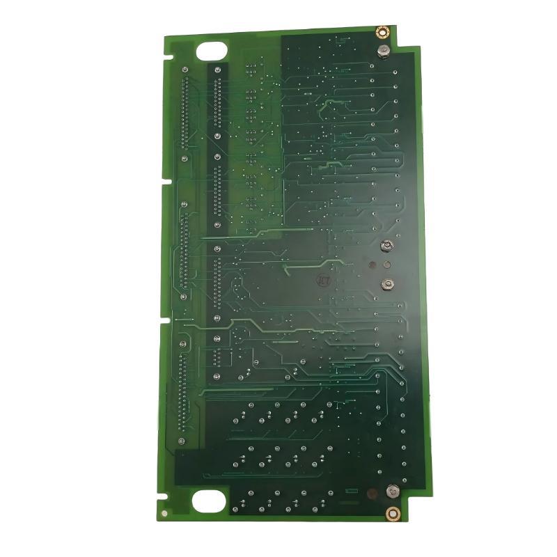
- GE
- IS200TVIBH2BCC
- Vibration Terminal Block
- USA
- 250 x 150 x 50 mm
- 0.79 kg
- Xiamen, China
- New & In Stock
- T/T, PayPal, Western Union
- 1 Year
- 1-3 Working Days
- DHL, UPS, TNT, FedEx and EMS.
- 24-Hour Service
- COO
- 40
Our advantage

Global Logistics
We have a 10-year logistics and express cooperation agreement, so our products can be shipped to any place in the world.

Brand new and original
Our products are imported in bulk from the place of origin. Because of the cooperative relationship, our products are all original and 100% new.

24-hour service
We provide 7*24 hours service to our customers. We will be there whenever you need us.

Price advantage
All our products are priced very favorably because we have our own warehouse and supply.
| Company Information | |||
| [email protected] | |||
| Mobile | +8615980777398 | ||
| +8615980777398 | |||
| 15980777398 |
Product Overview
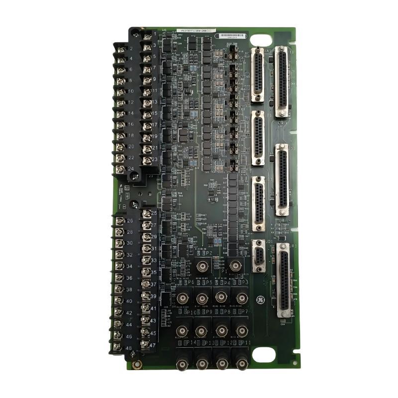
The GE IS200TVIBH2BCC Vibration Terminal Block is an industrial interface assembly designed to support vibration-related signal connections within compatible GE turbine, rotating-equipment, and industrial control systems. It provides an organized termination point between field vibration instrumentation and the associated monitoring, I/O, and control electronics.
Vibration monitoring plays an important role in the operation and maintenance of rotating machinery. Turbines, generators, compressors, pumps, motors, and other rotating equipment can generate vibration patterns that change when mechanical operating conditions change. A properly integrated vibration-monitoring system allows these signals to be transferred into an industrial control architecture for monitoring, alarming, diagnostics, and condition-based maintenance.
The GE IS200TVIBH2BCC has listed dimensions of 250 × 150 × 50 mm and a weight of approximately 0.79 kg. Its compact terminal-interface format is suitable for industrial control cabinets where vibration-related field wiring must be terminated, organized, and routed toward the appropriate monitoring electronics.
The terminal block is one part of a complete vibration-monitoring chain. It does not independently perform all vibration measurement or analysis functions. Instead, it provides the physical interface through which signals from compatible field devices can be connected to the wider control and monitoring system.
A simplified signal path is:
Rotating Equipment → Vibration Sensor → Field Cable → IS200TVIBH2BCC → Signal Interface / Monitoring Electronics → Control System
The exact electrical configuration, sensor types, and terminal assignments depend on the host equipment and engineering design.
Technical Specifications
| Parameter | Specification |
|---|---|
| Manufacturer | General Electric (GE) |
| Model | IS200TVIBH2BCC |
| Product Type | Vibration Terminal Block |
| Product Family | GE IS200 Series |
| Primary Function | Vibration signal termination and interface |
| Application | Vibration monitoring and rotating-equipment control |
| Interface Role | Field instrumentation signal interface |
| Installation | Industrial control cabinet |
| Assembly Type | Terminal / signal-interface assembly |
| Dimensions | 250 × 150 × 50 mm |
| Weight | 0.79 kg |
| Typical Equipment | Turbines, generators, compressors and rotating machinery |
| Signal Role | Vibration-related measurement and monitoring signals |
| Maintenance Function | Wiring inspection, signal verification and troubleshooting |
What Is the GE IS200TVIBH2BCC?
The GE IS200TVIBH2BCC is a Vibration Terminal Block designed to organize and terminate vibration-monitoring signal connections within compatible industrial control systems.
Rotating equipment produces mechanical movement as part of normal operation. Vibration sensors detect this movement and generate corresponding electrical signals. These signals must be transmitted reliably from the machine to the control or monitoring system.
The terminal block provides a structured connection point for this signal path.
In a typical installation:
Machine
↓
Vibration Transducer
↓
Sensor Cable
↓
IS200TVIBH2BCC
↓
Signal Conditioning / I/O
↓
Monitoring or Control Processor
↓
HMI / SCADA
This arrangement separates the field instrumentation wiring from the electronic processing section of the control cabinet.
Understanding Vibration Terminal Interfaces
Vibration-monitoring systems are used to observe the mechanical condition of rotating equipment.
Depending on the application, instrumentation may be used to monitor:
- Shaft vibration
- Bearing vibration
- Casing vibration
- Rotational movement
- Mechanical displacement
- Machine condition
- Abnormal vibration trends
Different machines can use different sensor technologies. Depending on the system, vibration measurement may involve accelerometers, velocity sensors, proximity probes, or other specialized transducers.
The IS200TVIBH2BCC functions at the interface level. The actual sensor technology and signal-processing method are determined by the complete monitoring system.
A properly organized terminal interface can make it easier to identify sensor circuits, inspect connections, and trace signals during commissioning or maintenance.
Function and Working Principle
Vibration Signal Termination
The primary function of the terminal block is to provide an organized termination point for vibration-related field wiring.
Signals generated by compatible vibration sensors enter the control cabinet through field cables and are connected to the appropriate interface points.
Secure termination is important because vibration-monitoring systems can be affected by loose or damaged connections.
Signal Routing
After termination, vibration signals can be routed toward the appropriate signal-conditioning or monitoring hardware.
The terminal assembly therefore creates a clear physical path between field instrumentation and electronic monitoring equipment.
Equipment Condition Monitoring
The connected vibration signals can be processed by the associated monitoring system to provide information about machine operating conditions.
Depending on system configuration, this information may support:
- Vibration trending
- Alarm generation
- Condition monitoring
- Equipment diagnostics
- Maintenance planning
- Protective functions
The terminal block itself does not establish the monitoring thresholds or diagnostic algorithms.
Continuous Monitoring
When integrated into an automated monitoring system, vibration measurements can be observed continuously.
Continuous monitoring provides an opportunity to identify changes in machine behavior without relying solely on periodic manual inspection.
Role in Industrial Automation
The IS200TVIBH2BCC can form part of the instrumentation and interface layer of an industrial turbine or rotating-equipment control system.
A typical architecture can be divided into several functional layers.
Field Equipment
Sensors and instruments detect physical conditions from the turbine or rotating machine.
Signal Interface
Terminal assemblies provide organized electrical connections between field wiring and control electronics.
Signal Processing
Associated I/O or monitoring hardware conditions and processes incoming signals.
Control System
A control processor uses configured logic to monitor equipment and perform required control functions.
Supervisory System
HMI and SCADA systems can present measurements, trends, alarms, and equipment status to operators.
The terminal block therefore supports the connection between physical equipment and the electronic control architecture.
Industrial Applications
Turbine Vibration Monitoring
Turbines contain high-speed rotating components that require careful monitoring. Vibration measurements can provide useful information about the mechanical behavior of turbine assemblies.
Generator Monitoring
Generators contain rotating components and bearings that may be monitored using vibration instrumentation as part of an overall condition-monitoring strategy.
Compressor Systems
Large industrial compressors often use vibration monitoring to observe mechanical behavior and identify changes that require investigation.
Pumping Equipment
Industrial pumps can develop imbalance, misalignment, bearing wear, or other mechanical conditions that may be reflected in vibration measurements.
Motor Monitoring
Large electric motors can also use vibration sensors to support equipment-condition monitoring.
Industrial Rotating Machinery
Fans, blowers, gearboxes, turbine auxiliaries, and other rotating equipment can be integrated into vibration-monitoring architectures where appropriate.
Vibration Signal Architecture
A typical vibration-monitoring system can be represented as:
Rotating Equipment
↓
Vibration Sensor
↓
Field Wiring
↓
GE IS200TVIBH2BCC
↓
Signal Conditioning / I/O
↓
Monitoring Processor
↓
Control System
↓
HMI / SCADA
Each component performs a different function.
The sensor detects physical movement, the cable carries the electrical signal, and the terminal block provides an organized connection point. Signal-conditioning and monitoring electronics then process the measurement for use by the control architecture.
This layered design helps simplify system maintenance and troubleshooting.
Installation Guidelines
Correct installation is important for reliable vibration-signal transmission.
Verify Part Identification
Before installation, verify:
- Complete part number
- IS200TVIBH2BCC identification
- Revision designation
- Terminal arrangement
- Connector configuration
- Cabinet location
- Associated monitoring hardware
- Host-system configuration
A similar-looking GE IS200 assembly should not be assumed to be electrically interchangeable.
Inspect the Terminal Block
Before installation, inspect the assembly for:
- Damaged terminals
- Loose hardware
- Cracked components
- Corrosion
- Contamination
- Damaged connectors
- Signs of overheating
- Mechanical damage
Verify Sensor Wiring
Sensor cables should be checked carefully before connection.
Important checks include:
- Correct cable identification
- Terminal position
- Connector seating
- Cable integrity
- Shielding
- Grounding
- Cable routing
Incorrect sensor wiring can result in missing, unstable, or misleading vibration measurements.
Cabinet Wiring and Cable Management
Industrial turbine and rotating-equipment cabinets can contain many instrumentation circuits. Proper cable management is important for both signal integrity and maintenance efficiency.
Recommended practices include:
- Clearly identify every vibration sensor cable.
- Keep instrumentation wiring organized.
- Separate signal cables from high-power conductors.
- Avoid unnecessary parallel runs alongside power cables.
- Secure cables against mechanical movement.
- Maintain access to terminal points.
- Preserve established wire numbering during replacement.
Proper organization makes it easier to trace an individual vibration channel during troubleshooting.
EMC and Electrical Noise Considerations
Vibration-monitoring signals can be affected by electrical interference depending on the sensor and signal architecture.
Potential interference sources include:
- Variable-frequency drives
- Motors
- Generators
- Switching equipment
- Power cables
- High-current conductors
- Improper grounding
- Incorrect shielding
To reduce potential interference:
- Route instrumentation cables separately from power cables.
- Follow the host-system grounding requirements.
- Use the appropriate cable-shielding method.
- Avoid unnecessary cable loops.
- Maintain secure terminal connections.
- Keep damaged or poorly shielded cables out of service.
The correct EMC arrangement should follow the engineering requirements of the complete monitoring system.
Grounding and Shielding
Correct grounding is essential when working with sensitive instrumentation.
Technicians should verify:
- Cabinet grounding
- Signal reference
- Sensor grounding
- Cable shielding
- Terminal connections
- Ground continuity
Shield termination should follow the applicable system design. A universal grounding method should not be assumed for every vibration-monitoring installation.
Grounding problems can appear as signal noise, unstable readings, unexpected alarms, or intermittent measurements.
Integration With Monitoring and Control Systems
The IS200TVIBH2BCC can be integrated into a larger equipment-condition monitoring architecture.
A typical arrangement is:
Vibration Sensors → IS200TVIBH2BCC → Monitoring Electronics → Control Processor → HMI / SCADA
The monitoring system can use vibration information for:
- Equipment trending
- Abnormal-condition alarms
- Maintenance analysis
- Diagnostic information
- Equipment status
- Protective actions where specifically engineered
The terminal block provides the connection infrastructure while the associated monitoring and control electronics perform signal processing and decision-making.
Commissioning Procedure
A structured commissioning process should be used after installation or replacement.
Step 1: Confirm Hardware
Verify the exact GE IS200TVIBH2BCC part number and applicable revision.
Step 2: Inspect Terminals
Check terminal connections, connectors, and physical condition.
Step 3: Verify Field Wiring
Compare sensor wiring against the applicable system drawings.
Step 4: Check Grounding
Verify grounding and shielding arrangements.
Step 5: Confirm Associated Electronics
Check the relevant signal-conditioning and monitoring hardware.
Step 6: Verify Signal Acquisition
Confirm that expected vibration signals are reaching the monitoring system.
Step 7: Compare Measurements
Compare measurements against suitable operating references or known machine conditions.
Step 8: Verify Alarm Functions
Where applicable, perform controlled testing of configured alarms and monitoring functions.
Step 9: Document Results
Record hardware identification, wiring checks, test results, and any maintenance changes.
Troubleshooting the IS200TVIBH2BCC
When a vibration-monitoring problem occurs, technicians should investigate the complete signal chain.
No Vibration Signal
Possible causes include:
- Failed sensor
- Damaged cable
- Loose terminal
- Incorrect wiring
- Connector problem
- Signal-conditioning fault
- Monitoring-system configuration issue
The sensor and cable should be checked before replacing the terminal block.
Unstable Measurement
An unstable vibration signal may result from:
- Electrical interference
- Poor grounding
- Shielding problems
- Loose connections
- Damaged cable
- Sensor mounting problems
- Signal-conditioning issues
Both electrical and mechanical causes should be considered.
Unexpectedly High Vibration
A high vibration reading does not automatically mean that the terminal block has failed.
Possible causes include:
- Actual machine vibration
- Sensor mounting problems
- Sensor degradation
- Electrical interference
- Cable faults
- Incorrect configuration
Machine operating conditions should be investigated alongside the electrical signal path.
Intermittent Signal
Intermittent behavior may be caused by:
- Loose terminal connections
- Damaged sensor cable
- Connector movement
- Vibration-induced wiring problems
- Poor shielding
- Sensor degradation
Because vibration is present at the monitored machine, cables and connectors should be mechanically secured.
Preventive Maintenance
Preventive maintenance should cover the terminal interface, wiring, sensors, and associated monitoring hardware.
Terminal Inspection
Check terminals for:
- Loose connections
- Corrosion
- Contamination
- Mechanical damage
Cable Inspection
Inspect sensor cables for:
- Abrasion
- Crushed sections
- Insulation damage
- Moisture ingress
- Excessive bending
- Loose conductors
Sensor Inspection
The condition and mounting of the vibration sensor should also be checked.
A damaged or poorly mounted sensor can produce incorrect measurements even when the terminal block and wiring are functioning correctly.
Trend Monitoring
Reviewing vibration trends over time can help identify gradual changes in machine behavior.
Cabinet Inspection
Maintain the control cabinet in a suitable condition and protect the terminal assembly from excessive dust, moisture, heat, and mechanical stress.
Replacement Considerations
When replacing the GE IS200TVIBH2BCC Vibration Terminal Block, the complete hardware identification should be verified before installation.
Important identification information includes:
- Full model number
- Revision
- Board markings
- Terminal arrangement
- Connector configuration
- Associated sensor wiring
- Existing cabinet position
- Host control-system configuration
The supplied physical dimensions are 250 × 150 × 50 mm, with a listed weight of 0.79 kg.
These dimensions are useful for cabinet planning and spare-parts management. However, physical compatibility does not guarantee electrical compatibility.
The replacement should therefore be matched against the complete system configuration and applicable technical documentation.
Physical Dimensions and Weight
The supplied physical specifications for the GE IS200TVIBH2BCC are:
| Physical Parameter | Specification |
|---|---|
| Length | 250 mm |
| Width | 150 mm |
| Height | 50 mm |
| Weight | 0.79 kg |
The 250 × 150 × 50 mm form factor provides a compact terminal-interface arrangement for industrial vibration-monitoring applications.
The listed weight of 0.79 kg should also be considered when planning handling, cabinet installation, and spare-parts logistics.
Compatible System Components
The IS200TVIBH2BCC can form part of a complete vibration-monitoring architecture containing components such as:
| Component | Typical Function |
|---|---|
| Vibration Sensor | Detects mechanical vibration |
| Proximity Sensor | Detects selected shaft or machine movement |
| Sensor Cable | Transfers measurement signals |
| Terminal Block | Provides field signal termination |
| Signal Conditioner | Conditions incoming sensor signals |
| I/O Interface | Transfers signals into the control architecture |
| Monitoring Processor | Processes vibration information |
| Control Processor | Executes configured control logic |
| HMI | Displays equipment information |
| SCADA System | Provides supervisory monitoring |
| Alarm System | Provides abnormal-condition notification |
The exact component combination depends on the host turbine or rotating-equipment control system.
Recommended Related GE IS200 Models
| Model | Product Description | General Role |
|---|---|---|
| IS200TVIBH2BBB | Vibration Terminal Block | Vibration signal interface |
| IS200TTURH1BCC | Turbine Terminal Block | Turbine field interface |
| IS200TTURH1BEC | Turbine Terminal Block | Turbine signal interface |
| IS200TTURH1BED | Turbine Terminal Block | Turbine field interface |
| IS200TSVOH1BBB | Servo Terminal Block | Servo signal interface |
| IS200TSVOH1BDC | Servo Terminal Block | Servo control interface |
| IS200TRLYH1BED | Relay Output Terminal Block | Relay output interface |
These related assemblies belong to the broader GE IS200 industrial control family. They should not be considered direct replacements for the IS200TVIBH2BCC without verifying the complete electrical configuration and host-system requirements.
Engineering Best Practices
Reliable vibration monitoring depends on the entire measurement chain.
Recommended engineering practices include:
- Verify the complete part number before installation.
- Record the hardware revision.
- Maintain accurate wiring drawings.
- Clearly label every vibration sensor circuit.
- Keep instrumentation cables separated from high-power conductors.
- Use appropriate shielding and grounding practices.
- Inspect terminals during scheduled maintenance.
- Check sensor mounting condition.
- Monitor vibration trends rather than relying only on individual readings.
- Investigate repeated signal faults at the system level.
- Perform functional testing after replacement or wiring modifications.
These practices can improve measurement reliability and reduce unnecessary replacement of functional hardware.
Key Advantages
Dedicated Vibration Interface
The IS200TVIBH2BCC provides a structured termination point for vibration-related field instrumentation.
Compact Cabinet Integration
Its listed 250 × 150 × 50 mm dimensions provide a compact format for industrial control cabinets.
Organized Sensor Wiring
A dedicated terminal assembly helps separate and organize field sensor connections.
Support for Equipment Condition Monitoring
Vibration signals can provide useful information about the condition of rotating machinery.
Maintenance-Friendly Design
Organized field connections simplify inspection, signal tracing, and troubleshooting.
Integration Into Industrial Control Architectures
The terminal block can participate in larger monitoring systems involving sensors, I/O electronics, processors, HMIs, and supervisory systems.
Technical FAQs
What is the GE IS200TVIBH2BCC?
The GE IS200TVIBH2BCC is a Vibration Terminal Block designed to provide an organized interface for vibration-monitoring field wiring within compatible GE industrial control systems.
What is the function of a vibration terminal block?
It provides a physical termination and routing point between vibration sensors and the associated signal-conditioning, I/O, monitoring, or control electronics.
What equipment can use vibration monitoring?
Vibration monitoring is commonly used with turbines, generators, compressors, pumps, motors, gearboxes, fans, and other rotating equipment.
Does the IS200TVIBH2BCC directly measure vibration?
The terminal block primarily provides the field-signal interface. The vibration sensor detects the physical condition, while associated monitoring electronics perform the required signal processing and analysis.
What are the dimensions of the IS200TVIBH2BCC?
The listed dimensions are 250 × 150 × 50 mm.
What is the weight of the IS200TVIBH2BCC?
The listed weight is approximately 0.79 kg.
What can cause a missing vibration signal?
Possible causes include sensor failure, cable damage, loose terminals, incorrect wiring, connector problems, signal-conditioning faults, or monitoring-system configuration issues.
Why can electrical noise affect vibration measurements?
Depending on the sensor and signal architecture, vibration signals can be sensitive to interference from motors, drives, generators, switching equipment, and poorly routed power cables.
Can another GE IS200 vibration terminal block replace the IS200TVIBH2BCC?
Not automatically. The complete model number, revision, terminal configuration, signal requirements, and host-system compatibility should be verified before replacement.
How should the IS200TVIBH2BCC be maintained?
Maintenance should include terminal inspection, sensor-cable inspection, connector checks, grounding and shielding verification, sensor inspection, cabinet inspection, and review of vibration trends.
Conclusion
The GE IS200TVIBH2BCC Vibration Terminal Block is a specialized industrial interface assembly designed to support vibration-monitoring signal connections within compatible GE turbine and rotating-equipment control architectures. It provides an organized termination point between vibration field instrumentation and the electronic monitoring system.
Vibration monitoring is an important component of modern equipment-condition monitoring because changes in vibration behavior can provide useful information about rotating machinery. A reliable terminal interface helps maintain a clear and serviceable signal path between sensors and the control system.
With listed dimensions of 250 × 150 × 50 mm and a weight of 0.79 kg, the IS200TVIBH2BCC provides a compact solution for industrial cabinet integration. Its performance as part of a complete monitoring system depends on correct sensor installation, field wiring, signal conditioning, grounding, shielding, and system configuration.
For replacement work, the complete IS200TVIBH2BCC part number and revision should be verified before installation. Proper wiring documentation, secure connections, appropriate cable management, preventive maintenance, and system-level troubleshooting can help maintain reliable vibration monitoring and support long-term operation of critical rotating equipment.