

ProductPRODUCT
Featured products



Contact Us
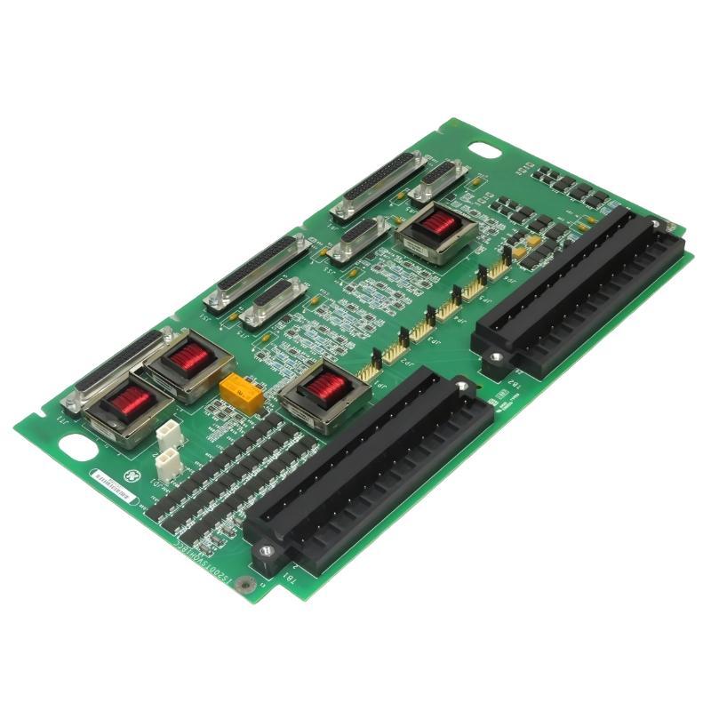
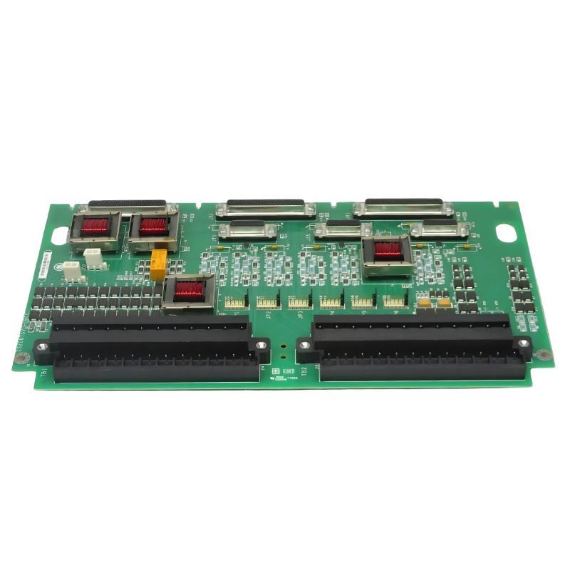
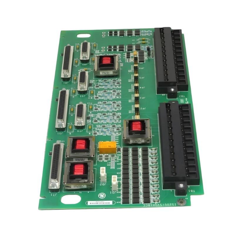
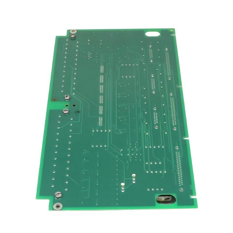
- GE
- IS200TSVOH1BDC
- Servo Terminal Block
- USA
- 330.2 x 20 x 178 mm
- 0.66 kg
- Xiamen, China
- New & In Stock
- T/T, PayPal, Western Union
- 1 Year
- 1-3 Working Days
- DHL, UPS, TNT, FedEx and EMS.
- 24-Hour Service
- COO
- 29
Our advantage

Global Logistics
We have a 10-year logistics and express cooperation agreement, so our products can be shipped to any place in the world.

Brand new and original
Our products are imported in bulk from the place of origin. Because of the cooperative relationship, our products are all original and 100% new.

24-hour service
We provide 7*24 hours service to our customers. We will be there whenever you need us.

Price advantage
All our products are priced very favorably because we have our own warehouse and supply.
| Company Information | |||
| [email protected] | |||
| Mobile | +8615980777398 | ||
| +8615980777398 | |||
| 15980777398 |
Product Overview
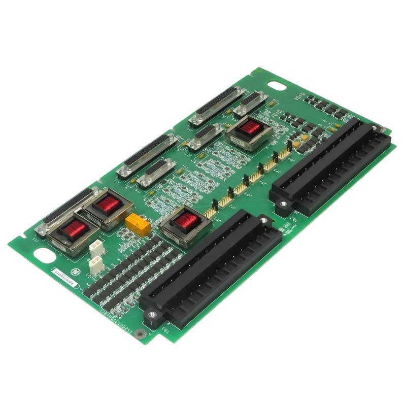
The GE IS200TSVOH1BDC Servo Terminal Block is an industrial control interface component designed for integration into compatible GE automation and motion-control systems. As a dedicated terminal interface, the IS200TSVOH1BDC provides an organized connection point for servo-related wiring, allowing field devices and control electronics to be connected within a structured industrial control architecture.
Servo control systems depend on reliable electrical connections for command signals, feedback signals, enable circuits, status information, and associated control functions. A properly configured terminal block helps organize these circuits and provides a practical point for installation, inspection, testing, and maintenance.
The GE IS200TSVOH1BDC has listed dimensions of 330.2 × 20 × 178 mm and a weight of approximately 0.66 kg. Its elongated construction is suitable for installation within compatible GE control equipment and industrial electrical cabinets.
The IS200TSVOH1BDC is not a standalone servo drive or controller. Instead, it functions as part of a larger servo-control system that may include control processors, servo drives, motors, feedback devices, I/O assemblies, terminal interfaces, communication hardware, and operator interfaces.
Technical Specifications
| Parameter | Specification |
|---|---|
| Manufacturer | General Electric (GE) |
| Model | IS200TSVOH1BDC |
| Product Type | Servo Terminal Block |
| Product Family | GE Industrial Control Hardware |
| Primary Function | Servo signal and wiring interface |
| Board Type | Terminal Block / Interface Assembly |
| Application | Industrial Servo and Motion Control |
| System Role | Servo field and control-system interface |
| Dimensions | 330.2 × 20 × 178 mm |
| Weight | 0.66 kg |
| Installation | Compatible GE industrial control equipment |
| Mounting | Control cabinet / equipment rack |
| Typical Applications | Servo systems, motion control, industrial automation |
What Is the GE IS200TSVOH1BDC?
The GE IS200TSVOH1BDC is a GE Servo Terminal Block intended to provide an organized electrical interface for servo-related circuits within compatible industrial control equipment.
In an industrial motion-control system, the controller must exchange information with servo drives and other field devices. These connections can include command signals, enable circuits, feedback signals, status information, and fault-related signals.
The terminal block provides a structured connection point within this architecture.
A simplified system can be represented as:
Industrial Controller → Servo Interface → IS200TSVOH1BDC → Servo Drive → Servo Motor
Feedback information follows a corresponding path:
Servo Motor / Feedback Device → IS200TSVOH1BDC → Control System
The exact circuit arrangement depends on the host GE equipment and system configuration.
Understanding Servo Terminal Blocks
A servo terminal block is an important part of the physical wiring architecture of a motion-control system.
Servo systems commonly require more complex electrical interfaces than simple motor starter applications because the control system may need both command and feedback information.
Typical servo-system circuits can include:
- Motion command signals
- Servo enable signals
- Status signals
- Fault signals
- Feedback signals
- Interlock circuits
- Control signals
- Auxiliary interface signals
The IS200TSVOH1BDC provides a structured location for these types of connections when used in a compatible system.
A well-organized terminal architecture can make it easier for technicians to trace individual circuits and identify problems during maintenance.
Function and Working Principle
Servo Signal Connection
The primary role of the IS200TSVOH1BDC is to provide an electrical connection interface for servo-related circuits.
The terminal block forms part of the physical path between control-system electronics and associated servo equipment.
Command Signal Routing
A control processor or motion-control system may generate commands that must be transmitted to a servo drive.
The terminal interface helps provide the physical wiring path through which these signals are transferred.
Feedback Signal Routing
Servo control often depends on feedback from the motor or mechanical system.
Feedback can provide information about actual motion conditions, allowing the control system to compare commanded and measured behavior.
The terminal block forms part of the connection between the feedback device and the associated control architecture.
Enable and Status Circuits
Servo equipment may require enable, status, interlock, or fault-related signals.
Organizing these circuits through a dedicated terminal assembly helps improve wiring clarity and maintenance accessibility.
Maintenance and Testing
Terminal blocks provide convenient locations for inspection and circuit verification.
During maintenance, technicians can use the terminal interface to trace wiring and identify whether a problem exists in the field device, cable, interface, or control hardware.
Role in Industrial Motion-Control Systems
The GE IS200TSVOH1BDC Servo Terminal Block can form part of a distributed industrial motion-control architecture.
A simplified structure is:
Machine Controller
↓
Motion-Control Logic
↓
Servo Interface
↓
IS200TSVOH1BDC
↓
Servo Drive
↓
Servo Motor
↓
Mechanical Load
Feedback travels in the opposite direction:
Motor / Feedback Device
↓
IS200TSVOH1BDC
↓
Servo Interface
↓
Motion Controller
This arrangement supports closed-loop machine control when the system is designed around feedback-based servo operation.
Industrial Applications
Automated Manufacturing Machinery
Servo systems are frequently used in automated manufacturing equipment where controlled movement and repeatable positioning are required.
Applications may include:
- Assembly machinery
- Automated production lines
- Positioning equipment
- Indexing systems
- Precision handling systems
Packaging Equipment
Servo motors can provide precise movement for packaging operations such as feeding, indexing, cutting, forming, and product positioning.
A dedicated terminal interface helps organize the associated control and feedback wiring.
Material Handling
Automated material-handling systems can use servo drives for controlled positioning and coordinated movement.
Robotics and Motion Platforms
Robotic systems and positioning mechanisms often require feedback-based motor control. The servo terminal interface can form part of the electrical architecture connecting these devices with the controller.
Industrial Processing Equipment
Specialized process machinery may use servo-controlled mechanisms for adjustment, positioning, dosing, or material handling.
General Factory Automation
Servo technology is widely used in industrial automation systems where conventional fixed-speed motors cannot provide the required positioning or motion performance.
Servo Signal Architecture
The exact terminal assignments for the IS200TSVOH1BDC depend on the host system. However, servo-control architectures commonly contain several signal categories.
| Signal Category | General Purpose |
|---|---|
| Command Signals | Defines desired motor movement |
| Enable Signals | Allows servo operation |
| Feedback Signals | Reports actual motion |
| Status Signals | Indicates equipment condition |
| Fault Signals | Reports abnormal conditions |
| Interlock Signals | Coordinates machine safety and operation |
| Auxiliary Signals | Supports associated system functions |
The table describes general servo-system signal categories rather than a specific terminal assignment for the IS200TSVOH1BDC.
Terminal wiring should always be performed according to the applicable equipment documentation.
System Integration
The IS200TSVOH1BDC should only be installed in a compatible GE control architecture.
Before installation, verify:
- Complete part number
- Revision designation
- Terminal identification
- Connector arrangement
- Servo-drive interface
- Motor configuration
- Feedback wiring
- Control-board configuration
- Host equipment
- Existing system documentation
The complete IS200TSVOH1BDC identification should be recorded before removing an existing assembly.
A terminal block with similar physical dimensions should not automatically be considered interchangeable.
Installation Guidelines
Verify the Part Number
Confirm the complete IS200TSVOH1BDC identification and applicable revision information.
Document Existing Wiring
Before disconnecting the existing terminal block, document:
- Wire numbers
- Terminal positions
- Connector locations
- Servo-axis identification
- Feedback connections
- Control-system connections
Clear documentation helps prevent wiring errors during replacement.
Place the Machine in a Safe State
Servo equipment can produce mechanical movement when control signals are restored.
The machine should therefore be placed into the appropriate maintenance and safe state before installation work begins.
Inspect the Terminal Block
Inspect the assembly for:
- Physical damage
- Loose terminals
- Corrosion
- Contamination
- Discoloration
- Signs of overheating
- Damaged connectors
Install the Assembly
Mount the IS200TSVOH1BDC in the designated location and secure it according to the applicable equipment requirements.
Restore Wiring
Reconnect all conductors according to the documented configuration.
Verify Connections
Check both command and feedback circuits before returning the servo system to normal operation.
Cabinet Wiring and Cable Management
Servo systems can contain both high-power motor cables and sensitive control or feedback wiring.
Good cable management is therefore important for reliable operation.
Recommended practices include:
- Keep servo cables clearly labeled.
- Avoid unnecessary cable bending.
- Secure cables against vibration.
- Separate sensitive feedback cables from high-power conductors where required.
- Protect cables from abrasion.
- Avoid excessive mechanical stress on terminals.
- Maintain suitable grounding practices.
- Keep connectors clean and secure.
Correct cable organization also makes future troubleshooting faster.
EMC and Electrical Noise Considerations
Servo drives use switching electronics that can generate electromagnetic interference.
Electrical noise may affect sensitive command or feedback circuits if installation practices are inadequate.
Possible symptoms include:
- Intermittent feedback
- Servo alarms
- Position instability
- Communication errors
- Unexpected signal changes
- Motion irregularities
Appropriate EMC practices may include:
- Proper grounding
- Suitable cable routing
- Cable separation
- Appropriate shielding
- Secure terminal connections
The actual EMC requirements should be determined from the host equipment and installation design.
PLC, Motion Controller, HMI and SCADA Integration
The IS200TSVOH1BDC can form part of a larger automation architecture involving multiple control layers.
| System Component | General Function |
|---|---|
| PLC / Control Processor | Executes machine logic |
| Motion Controller | Generates motion commands |
| Servo Interface | Connects control signals |
| IS200TSVOH1BDC | Servo terminal interface |
| Servo Drive | Controls motor operation |
| Servo Motor | Produces controlled mechanical motion |
| Feedback Device | Reports actual motion |
| HMI | Operator monitoring |
| SCADA | Supervisory monitoring |
| Engineering Station | Configuration and diagnostics |
The exact system configuration depends on the GE control platform and machine design.
Commissioning Procedure
A systematic commissioning procedure should be performed after installation or replacement.
Step 1: Visual Inspection
Inspect the terminal assembly, cables, connectors, and surrounding control equipment.
Step 2: Wiring Verification
Confirm that every conductor is connected according to the applicable documentation.
Step 3: Feedback Verification
Check that the associated feedback circuit is connected correctly and that the controller receives the expected information.
Step 4: Controller Diagnostics
Review available diagnostic information for servo, I/O, communication, and control faults.
Step 5: Enable Verification
Confirm that the servo enable and associated interlock conditions are correct.
Step 6: Controlled Motion Test
Perform an initial movement test under controlled conditions according to the machine commissioning procedure.
Step 7: Feedback Confirmation
Verify that commanded and actual movement information correspond correctly.
Step 8: Final Inspection
Confirm that all terminal connections, cables, mounting hardware, and cabinet components are secure.
Troubleshooting the IS200TSVOH1BDC
Servo Does Not Start
If the servo does not respond, inspect:
- Servo power
- Enable circuit
- Command wiring
- Terminal connections
- Servo-drive status
- Controller status
- Feedback circuit
- Diagnostic messages
The terminal block should not be assumed to be the fault source until the complete circuit has been checked.
Feedback Signal Fault
A feedback problem may be caused by:
- Damaged cable
- Loose terminal
- Incorrect wiring
- Feedback-device fault
- Electrical interference
- Interface problems
- Control configuration
Trace the complete feedback path from the motor or feedback device through the terminal block and into the control system.
Intermittent Operation
Intermittent servo behavior can result from:
- Loose connections
- Vibration
- Cable damage
- Connector problems
- Electrical noise
- Temperature-related connection changes
- Servo-drive faults
Inspection should cover both electrical and mechanical conditions.
Unexpected Motion
Unexpected servo movement should be treated as a serious machine-control condition.
Possible causes include:
- Incorrect command wiring
- Incorrect feedback wiring
- Enable-circuit problems
- Configuration errors
- Control-logic issues
- Servo-drive problems
- Mechanical faults
The machine should be placed into the appropriate safe state before detailed troubleshooting.
Fault Appears After Replacement
If the servo system develops a fault immediately after replacing the terminal block, check:
- Correct part number
- Revision
- Connector positions
- Wire locations
- Feedback wiring
- Enable circuits
- Control configuration
A wiring error can produce symptoms that initially appear to be a hardware failure.
Preventive Maintenance
Regular inspection of the servo terminal interface can help maintain system reliability.
Terminal Inspection
Inspect terminals for:
- Looseness
- Corrosion
- Contamination
- Overheating
- Physical damage
Cable Inspection
Check servo and feedback cables for:
- Abrasion
- Damaged insulation
- Excessive bending
- Mechanical stress
- Loose connections
Connector Inspection
Verify that connectors remain correctly seated and free from contamination.
Vibration Checks
Industrial machinery can generate continuous vibration that may gradually affect electrical connections.
Cabinet Environment
Maintain suitable temperature, ventilation, humidity, and cleanliness around the control equipment.
Diagnostic Monitoring
Review recurring servo alarms and feedback-related errors.
Repeated alarms may indicate an underlying wiring, motor, drive, feedback, or control-system problem.
Replacement and Spare-Part Planning
When sourcing a replacement for the GE IS200TSVOH1BDC Servo Terminal Block, the complete part number should be verified.
Important information includes:
- IS200TSVOH1BDC
- Revision designation
- Terminal arrangement
- Connector configuration
- Servo-axis assignment
- Feedback arrangement
- Associated drive
- Host control system
The physical dimensions and weight should also be considered during inventory and logistics planning.
A replacement should be selected based on electrical and system compatibility rather than physical appearance alone.
Physical Dimensions and Weight
The listed physical specifications for the GE IS200TSVOH1BDC Servo Terminal Block are:
- Dimensions: 330.2 × 20 × 178 mm
- Weight: 0.66 kg
These specifications can be useful for:
- Control cabinet planning
- Mechanical installation
- Spare-parts inventory
- Shipping preparation
- Replacement planning
- Maintenance documentation
The elongated 330.2 × 20 × 178 mm format provides a practical terminal-interface form factor for industrial control equipment.
Compatible System Components
The IS200TSVOH1BDC may form part of a larger GE industrial motion-control system containing:
| Component | General Function |
|---|---|
| GE Control Processor | Executes machine logic |
| Motion-Control Hardware | Generates motion commands |
| Servo Drive | Controls servo motor |
| Servo Motor | Provides controlled movement |
| Feedback Device | Provides actual motion information |
| Terminal Boards | Provides field wiring interfaces |
| I/O Hardware | Handles control signals |
| Communication Hardware | Transfers system data |
| HMI | Operator interface |
| Engineering Station | Configuration and diagnostics |
The exact combination of components depends on the host GE system.
Recommended Related GE Models
| GE Model | Product Type | General Role |
|---|---|---|
| IS200TSVOH1BBB | Servo Terminal Block | Servo signal interface |
| IS200TRPGH1BDD | Main Trip Terminal Block | Trip circuit interface |
| IS200TRLYH1BED | Relay Output Terminal Block | Relay output interface |
| IS200TRLYH1BFD | Relay Output Terminal Block | Relay output interface |
| IS200TRLYH1BGF | Relay Output Terminal Block | Relay output interface |
| IS200TBC1H1BCE | Mark VI Contact Terminal Block | Contact signal interface |
| IS200TBCIH1BBC | Contact Input Terminal Block | Contact input interface |
| IS200TDBTH6ACD | Discrete Terminal Block | Discrete signal interface |
These are related GE terminal and interface assemblies. They should not be treated as direct replacements for the IS200TSVOH1BDC without confirming the host-system configuration and electrical requirements.
Engineering Best Practices
Reliable servo operation requires attention to the complete electrical and mechanical system.
Recommended practices include:
- Verify the full part number before replacement.
- Record revision information.
- Document all wiring before disconnecting terminals.
- Maintain clear servo-axis identification.
- Use appropriate ESD protection.
- Follow machine safety procedures before working on servo equipment.
- Maintain suitable EMC and grounding practices.
- Inspect terminals and connectors regularly.
- Monitor recurring servo alarms.
- Maintain accurate electrical documentation.
- Keep correctly identified spare terminal assemblies available.
These practices can reduce wiring errors and improve the reliability of industrial motion-control systems.
Key Advantages
Dedicated Servo Interface
The GE IS200TSVOH1BDC provides a dedicated terminal interface for servo-related circuits within compatible GE control architectures.
Organized Servo Wiring
The terminal-block format helps organize command, feedback, status, and associated servo circuits.
Maintenance Accessibility
A structured terminal interface provides a practical location for inspection, circuit tracing, and maintenance.
Industrial Motion-Control Integration
The assembly can form part of systems involving servo drives, motors, feedback devices, controllers, and automated machinery.
Compact Cabinet Form Factor
With listed dimensions of 330.2 × 20 × 178 mm, the assembly is suitable for integration into industrial control cabinets and equipment.
Technical FAQs
What is the GE IS200TSVOH1BDC?
The GE IS200TSVOH1BDC is a Servo Terminal Block designed to provide an organized electrical interface for servo-related circuits within compatible GE industrial control systems.
What is the main function of a servo terminal block?
Its general function is to provide a structured connection point for servo command, feedback, status, enable, and related electrical circuits.
What are the dimensions of the IS200TSVOH1BDC?
The listed dimensions are 330.2 × 20 × 178 mm.
How much does the IS200TSVOH1BDC weigh?
The listed weight is approximately 0.66 kg.
Is the IS200TSVOH1BDC a servo drive?
No. It is a Servo Terminal Block, not a standalone servo drive or servo motor.
What equipment can use this type of terminal interface?
It can form part of industrial motion-control systems involving servo drives, servo motors, feedback devices, controllers, and automated machinery.
What can cause servo feedback problems?
Potential causes include damaged feedback cables, loose terminals, incorrect wiring, feedback-device faults, electrical interference, interface problems, or control-system configuration issues.
Can the IS200TSVOH1BBB replace the IS200TSVOH1BDC?
A similar model should not automatically be considered interchangeable. The complete part number, revision, terminal configuration, electrical function, and host-system requirements should be verified before replacement.
Why is cable management important for servo systems?
Servo drives can generate electrical noise, while feedback circuits may be sensitive to interference. Proper cable routing, grounding, shielding, and separation can help maintain reliable signal transmission.
What should be checked before replacing the terminal block?
Verify the complete IS200TSVOH1BDC identification, revision, terminal arrangement, wiring, associated servo equipment, feedback configuration, and host control system.
Conclusion
The GE IS200TSVOH1BDC Servo Terminal Block is an industrial interface component designed to organize and connect servo-related electrical circuits within compatible GE automation and motion-control systems. By providing a structured connection point between control hardware, servo drives, motors, feedback devices, and field wiring, the terminal block supports a maintainable and organized servo-system architecture.
The listed physical specifications are 330.2 × 20 × 178 mm with a weight of 0.66 kg. Its elongated form factor is suitable for integration into industrial control cabinets and equipment where organized servo wiring is required.
For replacement and maintenance, the complete IS200TSVOH1BDC identification should be verified together with the applicable revision, terminal arrangement, wiring configuration, associated servo equipment, and host-system requirements.
Proper wiring documentation, ESD protection, safe maintenance procedures, appropriate EMC practices, secure terminal connections, and systematic commissioning are essential for reliable operation. When correctly integrated into a compatible GE motion-control architecture, the IS200TSVOH1BDC Servo Terminal Block provides a practical and maintainable interface for industrial servo and automation applications.